 Open Access Article
Ionic liquids to monitor the nano-structuration and the surface functionalization of material electrodes: a proof of concept applied to cobalt oxyhydroxide†
Jacob
Olchowka
 *ab,
Tiphaine
Tailliez
a,
Lydie
Bourgeois
c,
Marie Anne
Dourges
c and
Liliane
Guerlou-Demourgues
 *ab
*ab
aCNRS, Univ. Bordeaux, Bordeaux INP, ICMCB UMR 5026, F-33600 Pessac, France. E-mail: jacob.olchowka@icmcb.cnrs.fr
bRS2E, Réseau Français sur le Stockage Electrochimique de l’Energie, FR CNRS 3459, F-80039 Amiens Cedex 1, France
cInstitut des Sciences Molaires, Univ. Bordeaux, UMR 5255, F-33405 Talence, France
First published on 10th April 2019
Abstract
This paper reports on an innovative and efficient approach based on the use of ionic liquids to govern the nano-structuration of HCoO2, in order to optimize the porosity and enhance the ionic diffusion through the electrode materials. In this work, we show that (1-pentyl-3-methyl-imidazolium bromide (PMIMBr) and 1-ethyl-3-methylimidazolium tetrafluoroborate (EMIMBF4)) ionic liquids (ILs) used as templates during the synthesis orientate the nanoparticle aggregation which leads to increase of the porosity and the average pore size of the electrode material. It is also demonstrated that the ILs are strongly bonded to the HCoO2 surface, leading to surface functionalized HCoO2 materials, also called nanohybrids. This surface tailoring stabilizes the material upon cycling and shifts the oxidation potential linked to the Co(III)/Co(IV) redox couple to lower voltage in an alkaline 5 M KOH electrolyte. The surface and porosity optimizations facilitate the ionic diffusion through the material, improve the electron transfer ability within the electrode and lead to greatly enhanced specific capacity in both alkaline 5 M-KOH and neutral 0.5 M-K2SO4 aqueous electrolytes (66.7 mA h g−1 and 47.5 mA h g−1 respectively for HCoO2–PMIMBr and HCoO2–EMIMBF4 compared to 18.1 mA h g−1 for bare HCoO2 in 5 M-KOH at 1 A g−1).
Introduction
Supercapacitors are electrochemical energy storage systems that have emerged over these last few years.1,2 Their numerous advantages such as high power density compared to traditional batteries, very long cycling lifetime and few-second charging time make them suitable for a wide range of applications from hybrid vehicles to portable electronics.3–5 Nevertheless, in order to enhance future supercapacitor industrial development and match specific applications, it is required to improve their energy densities. In the field of electrical double layer capacitors (EDLCs), which are the main commercialized systems, even if recent progress has been made to synthesize carbon with a very high specific surface area, the charge storage mechanism consisting in the physical adsorption of ions at the electrode surface limits the energy density.6–8 To overcome this problem, many research studies focus on materials for pseudocapacitive electrodes, which can provide much greater energy density than carbon electrodes thanks to the fast and reversible redox processes occurring at the material surface, and on battery-like faradaic electrodes for hybrid supercapacitor systems.9–11 Several metal oxides/(oxy)hydroxides such as RuO2, MnO2, Co(OH)2, Ni(OH)2, Co3O4, HCoO2, and NiCoO2 have been widely investigated and show promising features.12–21 However, for all of them, nano-structuration to optimize the electrode–electrolyte interface and a conductive scaffold to improve their electronic conductivity are crucial for maximizing their performances.22–24 Among all these electrode materials, non-stoichiometric layered cobalt oxyhydroxide (HCoO2) offers a two dimensional structure suitable for fast ionic diffusion as well as a good intrinsic electronic conductivity due the high oxidation state of cobalt, which favors electron transportation.25,26 While the HCoO2 pristine material usually exhibits a specific capacitance between 130 and 140 F g−1 in KOH electrolytes at 1 A g−1,27,28 different strategies were investigated to improve its electrochemical performances. For example, C. J. Raj et al. focused on nano-structuration by developing a hydrothermal synthesis to get HCoO2 nanorods with a specific capacitance of 177 F g−1 at 5 mV s−1,29 whereas Zhu et al. developed HCoO2/CNT (carbon nanotube) hybrids27,30 giving 270 F g−1 and 312 F g−1 at 1 A g−1. Other groups prepared HCoO2 thin films,31–33 or MWCNT/CoOOH multilayer films,34via synthesis strategies for which they claim an improved specific capacitance (up to 463 F g−1 at 1.8 A g−1 (ref. 31)), but the mass loading of the active material is usually very limited by this technique. More recently, Zhang et al. reported a method to grow ultrathin HCoO2 nanoflakes on nickel foam, exhibiting a surprisingly very high specific capacitance of 2550 F g−1 at 1.25 A g−1 in KOH, which demonstrates that developing nano-structuration strategies is essential to improve the electrochemical performances.25 It should be noted that these capacity values were often obtained in alkaline media, in which the charge storage processes are mainly faradaic, leading in most cases to non-rectangular curve shapes in cyclic voltammetry, so that expressing the capacitances in F g−1 is usually not relevant, and should be replaced by capacities in C or mA h g−1. Nevertheless, these capacity values are often not mentioned in the publications, which is the reason why, for the sake of convenience, only capacitance values in F g−1 are reported in this introduction.Ionothermal synthesis which is still poorly used for energy storage material synthesis could perfectly fulfil the nano-structuration criterion.35–37 The ionic liquids (IL) used as (co)solvent are also able to play the key role of surfactants and/or structure directing agents allowing us to tailor the size, the shape and the agglomeration/porosity of the synthesized inorganic nanomaterials and hybrid nanomaterials.38–44 In fact, ILs can form extended hydrogen-bond systems in the liquid state to be highly structured, which can serve as the “entropic driver” for spontaneous, well-defined, and extended ordering of nanoscale structures. Thus, synthesis in ionic liquids allows a better control on the nanostructuration of the materials (particles size, porosity, and pore size) than simple hybridization, where an inorganic material is impregnated on a conductive carbon-based material (graphene and carbon nanotubes). Moreover, during the synthesis, the ILs can be strongly bonded to the inorganic material surface to modify material characteristics such as the solubility, stability, chemical reactivity or energy transfer properties.36,39,45–49 For instance, B. G. Choi et al. synthesized a BMIMBF4–Co(OH)2 hybrid electrode material and have shown by DFT calculations that ILs tethered to the Co(OH)2 surface allow faster proton adsorption/desorption processes, which contribute to lowering the energy barrier of the pseudo-capacitive process, thus improving the electrochemical performances.46
In this work, we report on two IL–cobalt oxyhydroxide nanohybrid materials prepared by a precipitation method. The two imidazolium based ionic liquids, 1-pentyl-3-methyl-imidazolium bromide (PMIMBr) and 1-ethyl-3-methylimidazolium tetrafluoroborate (EMIMBF4), were chosen for (i) their availability compared to some other ionic liquids, (ii) their high intrinsic ionic conductivity, (iii) their hydrophilic character and (iv) their ability to be used as a structure directing agent50–53 and also because imidazolium has the ability to adsorb on the material surface, to functionalize the inorganic material and to facilitate H+ adsorption.46 We investigate in the present work the influence of the ionic liquid on the nano-structuration (porosity, pore size, and aggregation) of the nanomaterial and correlate it to the electrochemical performances. The materials have been tested in both KOH and K2SO4 aqueous electrolytes. The basic medium leads to “bulk” faradaic reactions inducing the best performances in terms of capacity and allows comparing our material to the literature. On the other hand, the “bulk” faradaic reactions are strongly limited in K2SO4 electrolyte, in which the behavior is expected to be more pseudocapacitive. Finally, beyond the important improvement of HCoO2 capacity, ionic conductivity and stability, we believe that this material design approach (nano-structuration and surface functionalization by ILs) is a proof of concept and can be transposed to other materials.
Experimental
The synthesis of beta-3 cobalt oxyhydroxide (named HCoO2) consists of a precipitation in an alkaline oxidizing medium starting from Co(II) solution. First, 3.18 g of Co(NO3)2·6H2O (10−2 mol) are dissolved in 300 mL of water. Then 11 mL of NaOH (2 M) are added dropwise to the solution under stirring. After some seconds, the unstable blue precipitate corresponding to alpha-Co(OH)2·xH2O formed because the sodium hydroxide addition turns pink and leads to the formation of beta-Co(OH)2. Afterwards, 7.5 mL of NaClO (48° Cl) are added dropwise to the solution in order to speed up the oxidation process leading to the oxyhydroxide phase. The solution is stirred overnight, centrifuged 6 times in water for 3 min at 4000 rpm and dried 24 h at 50 °C. The synthesis procedure for HCoO2–PMIMBr and HCoO2–EMIMBF4 is the same, except that 3 mL of 1-pentyl-3-methyl-imidazolium bromide (PMIMBr) and 3 mL of 1-ethyl-3-methylimidazolium tetrafluoroborate (EMIMBF4) are added respectively to the starting solution of water.X-ray diffraction (XRD) data for each material were collected with a Philips PANalytical X'Pert Pro diffractometer using cobalt Kα radiation (1.789 Å). The diffraction patterns were recorded for around 25 hours (1800.48 s per step) in the 10–110° (2θ) angular range, with a 0.0167° (2θ) step size and a 2.122° (2θ) active width in the detector.
Infrared spectroscopy measurements were performed on HCoO2-type materials using a FTIR Nicolet 6700 (Thermo Scientific) equipped with a diffuse reflectance accessory, suitable for studying powders and rough surfaces. Each sample was mixed with dried KBr – transparent in the middle IR range (400–4000 cm−1) – and finely ground (the mass ratio between each material and KBr being approximately 1![[thin space (1/6-em)]](https://www.rsc.org/images/entities/char_2009.gif) :
:![[thin space (1/6-em)]](https://www.rsc.org/images/entities/char_2009.gif) 10). Reflectance spectra were treated with the Kubelka–Munk law, which converts the reflectance to a signal proportional to the absorption coefficient. Infrared spectroscopy measurements were performed on ionic liquids using a FTIR Nicolet iS50 (Thermo Scientific) equipped with an attenuated total reflectance accessory (ATR) which requires no specific sample preparation. A single reflection system with a diamond crystal was used to analyse the sample. All the results obtained on powders were also confirmed by ATR.
10). Reflectance spectra were treated with the Kubelka–Munk law, which converts the reflectance to a signal proportional to the absorption coefficient. Infrared spectroscopy measurements were performed on ionic liquids using a FTIR Nicolet iS50 (Thermo Scientific) equipped with an attenuated total reflectance accessory (ATR) which requires no specific sample preparation. A single reflection system with a diamond crystal was used to analyse the sample. All the results obtained on powders were also confirmed by ATR.
Specific surface area determination and mesoporosity assessment were performed by recording nitrogen sorption isotherms with a Micromeritics ASAP2010 equipment (Micromeritics Corp., Norcross, GA, USA) after degassing each sample at 100 °C in a vacuum for a time interval long enough to reach a constant pressure (<10 μm Hg). The nitrogen adsorption–desorption isotherms were measured at liquid nitrogen temperature (77 K) with P/P0 ranging from 0 to 0.99. The BET equation was then applied between 0.01 and 0.3 relative pressure (P/P0) to calculate the specific surface areas (named BET-SA).54 Pore size distributions were evaluated by using the Barrett, Joyner, Halenda (BJH) model applied to the desorption branch of the isotherms.55 TGA measurements were performed on a SDT Q600 V3.8 Build 51 instrument under an air flow of 100 mL min−1 between room temperature and 700 °C.
Electrode preparation
Electrochemical measurements were performed in both aqueous 5 M-KOH and 0.5 M-K2SO4 electrolytes in a three electrode mode at room temperature. Platinum wire was used as the counter electrode in both cases, whereas Hg/HgO was used as the reference electrode in a basic electrolyte and Ag/AgCl in 0.5 M-K2SO4. The working electrode was prepared with a mixture of active material/carbon black/polytetrafluoroethylene in a weight ratio of 80/15/5. A disk of about 6 mm diameter of the electrode material, with a weight of ∼5 mg, was pressed for 30 s at 6 bar on nickel foam (current collector) for testing in KOH and on a stainless steel sheet for testing in K2SO4. This results in a 7 mm disk and hence an active material loading of ∼10.4 mg cm−2. The three electrodes (working electrode, reference electrode and counter electrode) were placed in the electrolyte in order to form an equilateral triangle and each electrode was separated from the other two by ≈16 mm. Electrochemical impedance measurements were performed under open-circuit conditions. A small AC perturbation amplitude of 10 mV versus the open-circuit potential was applied in a frequency range from 50 kHz down to 0.1 Hz. Cyclic Voltammetry (CV), Constant Current Charge/Discharge (CCCD) and Electrochemical Impedance Spectroscopy (EIS) were performed using an EC-lab potentiostat. The nickel foam alone was tested in 5 M KOH as the electrode material and the results have shown that it exhibits a negligible contribution to capacity.Results and discussion
XRD patterns presented in Fig. 1 confirm that all three syntheses lead to the formation of the rhombohedral-HCoO2 phase. The reported line indexation is performed with a hexagonal cell, with 3 CoO2 slabs per cell (space group: R![[3 with combining macron]](https://www.rsc.org/images/entities/char_0033_0304.gif) m, a = 2.851 Å and c = 13.150 Å). The addition of an ionic liquid during the synthesis did not lead to additional reflection peaks or any significant change in the XRD pattern, contrary to what was reported by Choi et al. for IL–Co(OH)2, where an additional broad reflection peak was observed compared to bare Co(OH)2.46 Moreover, the absence of shift of the (003) reflection, the interreticular distance of which corresponds to the interslab space, suggests that no additional species coming from the ionic liquid is inserted within the interslab space.56
m, a = 2.851 Å and c = 13.150 Å). The addition of an ionic liquid during the synthesis did not lead to additional reflection peaks or any significant change in the XRD pattern, contrary to what was reported by Choi et al. for IL–Co(OH)2, where an additional broad reflection peak was observed compared to bare Co(OH)2.46 Moreover, the absence of shift of the (003) reflection, the interreticular distance of which corresponds to the interslab space, suggests that no additional species coming from the ionic liquid is inserted within the interslab space.56
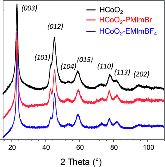 | ||
| Fig. 1 X-ray diffraction patterns of HCoO2 (black) (reference card 01-072-2280), HCoO2–PMIMBr (red) and HCoO2–EMIMBF4 (blue). | ||
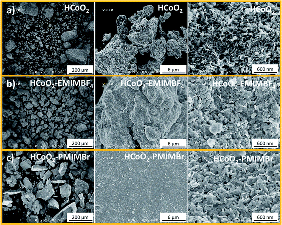
On the other hand, some differences could be observed in the aggregation of the particles. Scanning electron microscopy (SEM) images (Fig. 2) show that the HCoO2 nanoplatelets tend to produce bigger agglomerates when the ionic liquid is introduced during the synthesis. This effect seems to be more pronounced for HCoO2–PMIMBr and surprisingly, for this material, the primary particles tend to aggregate to form thick layers with a plane surface whereas the surface of the agglomerate looks less regular for HCoO2–EMIMBF4 and jagged for bare HCoO2. This tendency is confirmed when increasing the resolution. The surface of bare HCoO2 exhibits nanoplatelets stacked on their edge whereas they are piled up randomly in the presence of ionic liquids. For all materials, the length of the nanoplatelets is similar, ranging from 60 to 100 nm.
Fig. 3 shows the N2 adsorption/desorption isotherms as well as pore size distribution of the reference HCoO2 and the two HCoO2–EMIMBF4 and HCoO2–PMIMBr nanomaterials. Although the aggregation is different between the three materials, they all present a type IV isotherm including a hysteresis loop that indicates the existence of large mesopores and comparable adsorption surface areas. The BET surface area (BET-SA) increases by about 10% for HCoO2–PMIMBr (BET-SA = 135 m2 g−1) compared to bare HCoO2 (BET-SA = 122 m2 g−1) and decreases by about 15% for the other nano-hybrid HCoO2–EMIMBF4 (BET-SA = 104 m2 g−1). On the other hand, the distribution of pore volume differs. For HCoO2, a main part of the porosity comes from small mesopores with a diameter around 4 nm, the second population centered at 15 nm is less significant and a BJH desorption average pore diameter of 6.97 nm is calculated. Concerning the two nanohybrids, the mesopore population with a diameter of 4 nm is still present, but in minority compared to bigger mesopores (population with a diameter of ∼7 nm and ∼15 nm for HCoO2–EMIMBF4 and a diameter of ∼7 nm and ∼13 nm for HCoO2–PMIMBr). This leads to a BJH desorption average pore diameter of 8.34 nm and 9.77 nm for HCoO2–EMIMBF4 and HCoO2–PMIMBr respectively. Therefore, the BJH desorption cumulative volume of pores increases for the two nanohybrids (0.29 cm3 g−1 for HCoO2–EMIMBF4 and 0.34 cm3 g−1 for HCoO2–PMIMBr) compared to reference HCoO2 (0.24 cm3 g−1), which reveals a higher porosity for the materials synthesized in the presence of ionic liquids.
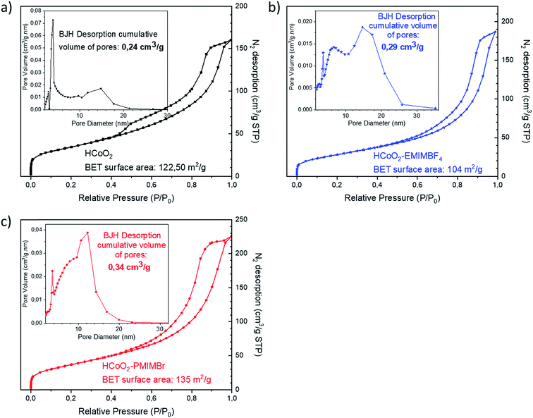 | ||
| Fig. 3 N2 adsorption/desorption isotherms as well as pore size distribution of (a) HCoO2 (b) HCoO2–EMIMBF4 and (c) HCoO2–PMIMBr. | ||
ILs are well known for their ability to adsorb on the surface of nanomaterials and to influence material morphology and aggregation due to their steric hindrance effect and in this case, to increase the porosity and the pore size average.43,57,58 Imidazolium based ionic liquids are especially used in material synthesis since they can form hydrogen bonds with the electronegative element of the material surface and generate π–π stacking in the liquid phase to design structured materials.57,59 The formation mechanism proposed in our case is based on this last approach. For both HCoO2–EMIMBF4 and HCoO2–PMIMBr, the positively charged cations 1-ethyl-3-methylimidazolium and 1-pentyl-3-methylimidazolium can easily be adsorbed on the oxygen surface of the layered cobalt oxyhydroxide by electrostatic forces, leading to a hydrogen bond formed between the proton on the C2 position of the imidazolium ring (proton between the two nitrogen) and the surface oxygen (see ESI S1†). The proton in the C2 position is considered because of its higher Lewis acidity compared to the others.60 The generated π–π interactions between imidazole rings orient the adsorbed ionic liquid molecules parallel to each other and stabilize the functionalized nanomaterial. The self-organization of the two nanohybrid structures is confirmed by FTIR analyses and SEM-EDX. Fig. 4 showing the SEM-EDX elemental mappings demonstrates the presence of ionic liquid homogeneously distributed over the final nanohybrid materials. Atoms from the anionic part of the ionic liquid, “F” and “Br” for EMIMBF4 and PMIMBr respectively, were chosen as a reference for the mapping since a carbon film was used as a support. Quantitative analyses give a weight ratio of ∼0.7 wt% for fluoride and ∼1 wt% for bromide, which shows that ionic liquids are present in a low concentration, in good agreement with surface functionalization. These results are supported by thermogravimetric analysis (see ESI S2†) which shows a weight loss of 21% at 700 °C for the two nanohybrids versus 20% for reference HCoO2.
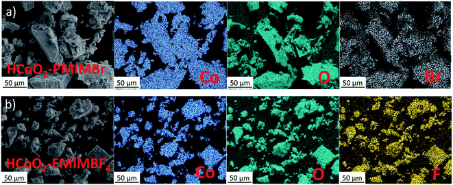 | ||
| Fig. 4 Energy dispersive X-ray (EDX) mapping analysis for the two nanohybrids, (a) HCoO2–PMIMBr and (b) HCoO2–EMIMBF4. | ||
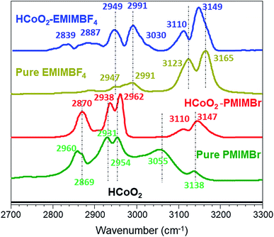
The surface functionalization is also clearly demonstrated by FTIR spectra, as shown in Fig. 5. For HCoO2–EMIMBF4, the two bands at 3110 and 3149 cm−1 that are assigned to the C–H stretching modes (νC–H) of the imidazolium ring are shifted to lower wavenumbers compared to the pure ionic liquid. This phenomenon suggests that strong interactions are involved between the ionic liquid and the surface of the inorganic material and can be attributed to both the hydrogen bonding between the acidic proton of the imidazolium ring and the oxygen surface of HCoO2 and to the π–π stack interactions of the aligned imidazolium rings which decrease the electronic density of C–H bonds of the ring and thus, weaken their bond strength.61 The νC–H mode of the aliphatic chain observed below 3050 cm−1 (ethyl and methyl) is also found to be influenced. New signals appear at 2839 cm−1 and 3030 cm−1, and existing bands gain in intensity. In this case, the mutual packing of positively charged imidazolium could influence the nitrogen–alkyl carbon bonds, changing the νC–H modes.61
For HCoO2–PMIMBr, the νC–H bands of the imidazolium ring are located at higher wavenumbers than those of the pure ionic liquid (3110 and 3147 cm−1 for HCoO2–PMIMBr compared to 3055 and 3138 cm−1 for PMIMBr). This phenomenon can be explained by the fact that upon surface adsorption and π–π stack interactions of imidazolium rings, the initial strong hydrogen bond between acidic hydrogen of the imidazolium ring and the bromide is weakened or broken, leading to a relocalization of bromide anions. These observations are in good agreement with the report of Cha et al. which shows a stronger interaction between halides and hydrogen of the imidazolium ring than between BF4− and the same hydrogen.62 Moreover, they also observed a similar continuous shift to higher wavenumbers when increasing the amount of diluted water in BMIMBr.62 In an analogous manner, the bands below 3000 cm−1 assigned to νC–H vibrations of the aliphatic chain shift to higher energies compared to pure PMIMBr. Hence, on the basis of the infrared data, it can be assumed that the ionic liquids are grafted to the surface of cobalt oxyhydroxide.
One could also notice that the νC–H bands of imidazolium rings are centered at very similar wavenumbers for the two nanohybrids (3110 and 3149 cm−1 for HCoO2–EMIMBF4 and 3110 and 3147 cm−1 for HCoO2–PMIMBr) although they are quite different in the pure ionic liquids (see Fig. 5). They are also very close to those reported in the literature where the π–π stack interactions of imidazolium based nanohybrids were observed (3103 and 3149 cm−1 for Co(OH)2–BMIMBF4, 3093 and 3151 cm−1 for Fe2O3–BMIMCl and 3099 and 3152 cm−1 for TiO2–EMIMBr).46,59,60
Electrochemical performances
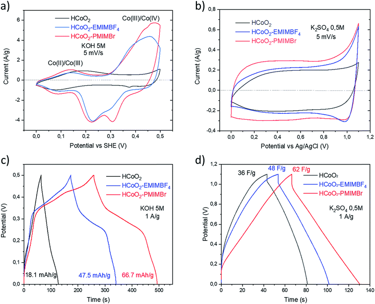
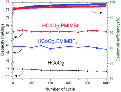
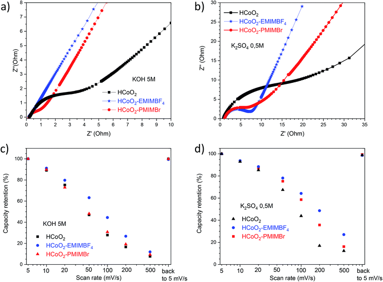
The electrochemical energy storage properties of the two nanohybrids were investigated by cyclic voltammetry (CV) and galvanostatic charge/discharge (GCD) in neutral (0.5 M-K2SO4) and basic (5 M-KOH) aqueous media and were compared to those of reference HCoO2. The CV curves measured at 5 mV s−1 in 5 M-KOH present rather symmetric shapes suggesting high reversibility of faradaic reactions (Fig. 6a). For both nanohybrids, the curves reveal two main redox peaks during the oxidation processes, the first one at 0.014 V and the second at 0.46–0.47 V which may respectively be assigned to the Co(II)/Co(III) and Co(III)/Co(IV) redox processes.25,27 These peaks are displaced to lower potential compared to bare HCoO2 for which the first peak is at 0.19 V and the second at 0.52 V (see ESI S3†).26 These displacements of redox potentials, most probably caused by the surface modification by the ionic liquids, allow shifting the Co(III)/Co(IV) oxidation potential inside the electrochemical windows of 5 M-KOH, leading to a higher peak current and higher charge capacity. It is quite reasonable to suppose that the ionic liquids grafted on the surface facilitate the insertion/deinsertion of the cations present in the electrolyte, which lowers the oxidation potential. Fig. 6c represents the galvanostatic charge–discharge profiles in a 5 M-KOH electrolyte, measured at 1 A g−1 for the three different electrode materials. The specific capacity evaluated from the discharged curves is clearly enhanced for the two nanohybrids, 47.5 mA h g−1 (342 F g−1) for HCoO2–EMIMBF4 and 66.7 mA h g−1 (480 F g−1) for HCoO2–PMIMBr, compared to the 18.1 mA h g−1 (130 F g−1) for HCoO2. The capacity observed for HCoO2–PMIMBr is higher than most of those reported in the literature for nanostructured HCoO2 and HCoO2 hybridized with a conductive carbon material.27–30,32–34,63 These results confirm the efficiency of the presented nano-structuration approach. Moreover, as shown in Fig. 7, these electrodes show an excellent cycling stability and a good coulombic efficiency over 1000 cycles. In a 0.5 M-K2SO4 electrolyte, the CV curves, represented in Fig. 6b, exhibit a rectangular shape characteristic of pseudocapacitive behavior. This proves that the energy storage behavior of an electrode strongly depends on the nature of the electrolyte, and the basic electrolyte favors faradaic reactions i.e. bulk proton intercalation/deintercalation compared to the K2SO4 one.64 In the neutral electrolyte, the pseudocapacitive behavior of the three electrode materials is also confirmed by galvanostatic charge–discharged (GCD) measurements (Fig. 6d) in which a nearly linear dependence of potential with time can be observed.65 Once again, the presence of an ionic liquid functionalizing the surface nanomaterial enhances the specific capacitance (36 F g−1, 48 F g−1 and 62 F g−1 for HCoO2, HCoO2–EMIMBF4, HCoO2–PMIMBr respectively). In a K2SO4 electrolyte, it can be assumed that most of the capacitance comes from electrode surface reactions (adsorption and surface redox reactions) due to the rectangular shape of CV curves. In spite of this last point, we could not establish direct correlation between the measured BET surface area (122 m2 g−1 for HCoO2, 104 m2 g−1 for HCoO2–EMIMBF4, and 135 m2 g−1 for HCoO2–PMIMBr) and the specific capacitance (which is much better for the nanohybrids). On the other hand, it can be noted that increasing the porosity of the material (0.24 cm3 g−1, 0.29 cm3 g−1 and 0.34 cm3 g−1 respectively for HCoO2, HCoO2–EMIMBF4 and HCoO2–PMIMBr), which may improve accessibility to the active sites, enhances the energy storage capacity of the nanomaterials (see Fig. 3). Nevertheless, these results demonstrate that, for pseudocapacitive materials, the BET surface area cannot be directly linked to the capacitance performance and that the nature of the ionic liquid used during the synthesis strongly influences the electrochemical performances.To study the effect of HCoO2 surface modification on conductivity properties, electrochemical impedance spectroscopy (EIS) analyses were performed in both K2SO4 and KOH electrolytes. The Nyquist plot of HCoO2, HCoO2–EMIMBF4 and HCoO2–PMIMBr in the K2SO4 electrolyte, shown in Fig. 8b, is composed of a semi-circle in the high-frequency region and a linear part in the low frequency one. The charge transfer resistance (RCT) calculated using the same equivalent circuit as that of Justin Raj et al. (see ESI S4†) is much smaller for the nanohybrid materials (RCT = 5.6 Ω and RCT = 5.7 Ω for HCoO2–EMIMBF4 and HCoO2–PMIMBr respectively) than for the bare material (RCT = 17.8 Ω).29 Furthermore, the most vertical line in the low-frequency region for the functionalized material and especially for HCoO2–EMIMBF4 also implies a better ionic diffusion through the electrode. The bigger average pore volume diameter for HCoO2–EMIMBF4 is most probably a key parameter that explains the better ionic diffusion. Finally, one of the direct consequences of the better interfacial charge transfer and ionic diffusion is the enhanced performance at a high cycling rate (see Fig. 8d and ESI S5†). HCoO2–EMIMBF4, which shows the best ionic conductivity, exhibits also the best capacity retention when increasing the cycling rate (e.g. 49% capacity retention at 200 mV s−1 compared to 5 mV s−1 against only 17% for HCoO2 and 36% for HCoO2–PMIMBr).
Similar interpretation can be made in a 5 M-KOH electrolyte; HCoO2–EMIMBF4 shows a lower charge transfer resistance as well as the best capacity retention at a high cycling rate (see Fig. 8a and c), whereas both HCoO2–EMIMBF4 and HCoO2–PMIMBr present a much better ionic conductivity (more vertical line in the low frequency range) than bare HCoO2.
Conclusion
This work shows that the synthesis of ionic liquid-based nanohybrids can be a way to develop new electrode materials with optimized electrochemical energy storage performances. During the synthesis of cobalt oxyhydroxide, ionic liquids are used both as templates to tailor the nano-structuration, leading to the generation of mesopores and facilitating the ionic diffusion, and also as reactants to functionalize the HCoO2 surface. This functionalization, demonstrated by SEM-EDX analyses and by FTIR measurements, lowers the Co3+/Co4+ oxidation potential and shifts it from the OER region towards the electrochemical stability window of a 5 M KOH electrolyte. Both the bare HCoO2 and the functionalized HCoO2 electrodes show rather pseudocapacitive behavior in neutral K2SO4 whereas faradaic reactions are enhanced in the 5 M-KOH electrolyte. Compared to the reference HCoO2, the specific capacity of HCoO2–PMIMBr has been multiplied by ∼3.7 in alkaline electrolytes and the specific capacitance has strongly increased in the neutral medium (66.7 mA h g−1 and 62 F g−1 respectively in 5 M-KOH and 0.5 K2SO4versus 18.1 mA h g−1 and 36 F g−1). Additionally, it is shown that the nature of the ionic liquid has a significant impact on the electrode performances. We consider this work as a proof of concept, which can be applied to other electrode materials.Conflicts of interest
There are no conflicts to declare.Acknowledgements
The authors would like to thank Philippe Dagault for thermogravimetry measurements and Catherine Denage for Scanning Electron Microscopy Imaging. The authors also thank the French National Research Agency (STORE-EX Labex Project ANR-10-LABX-76-01 for funding.References
- N. Choudhary, C. Li, J. Moore, N. Nagaiah, L. Zhai, Y. Jung and J. Thomas, Adv. Mater., 2017, 29, 1605336 CrossRef PubMed
.
- M. Salanne, B. Rotenberg, K. Naoi, K. Kaneko, P. L. Taberna, C. P. Grey, B. Dunn and P. Simon, Nat. Energy, 2016, 1, 16070 CrossRef CAS
.
- J. R. Miller and P. Simon, Science, 2008, 321, 651–652 CrossRef CAS PubMed
.
- Y. Wang, J. Guo, T. Wang, J. Shao, D. Wang and Y.-W. Yang, Nanomaterials, 2015, 5, 1667–1689 CrossRef CAS PubMed
.
- P. Simon and Y. Gogotsi, Nat. Mater., 2008, 7, 845–854 CrossRef CAS PubMed
.
- C. Bodin, E. Mourad, D. Zigah, S. Le Vot, S. A. Freunberger, F. Favier and O. Fontaine, Faraday Discuss., 2017, 1–12 Search PubMed
.
- H. Liu, Y. Zhang, Q. Ke, K. H. Ho, Y. Hu and J. Wang, J. Mater. Chem. A, 2013, 1, 12962–12970 RSC
.
- Z. Peng, Z. Guo, W. Chu and M. Wei, RSC Adv., 2016, 6, 42019–42028 RSC
.
- V. Augustyn, J. Come, M. A. Lowe, J. W. Kim, P. L. Taberna, S. H. Tolbert, H. D. Abruña, P. Simon and B. Dunn, Nat. Mater., 2013, 12, 518–522 CrossRef CAS PubMed
.
- A. González, E. Goikolea, J. Andoni and R. Mysyk, Renewable Sustainable Energy Rev., 2016, 58, 1189–1206 CrossRef
.
- V. Augustyn, P. Simon and B. Dunn, Energy Environ. Sci., 2014, 7, 1597 RSC
.
- M. Toupin, T. Brousse and D. Bélanger, Chem. Mater., 2004, 16, 3184–3190 CrossRef CAS
.
- G. Godillot, H. Huo, M. Ménétrier, L. Bourgeois, L. Guerlou-Demourgues and C. Delmas, J. Phys. Chem. C, 2012, 116, 26598–26607 CrossRef CAS
.
- A. Adán-más, R. G. Duarte, T. M. Silva, L. Guerlou-demourgues, M. Fátima and G. Montemor, Electrochim. Acta, 2017, 240, 323–340 CrossRef
.
- G. Godillot, P.-L. Taberna, B. Daffos, P. Simon, C. Delmas and L. Guerlou-Demourgues, J. Electrochem. Soc., 2016, 163, A2004–A2010 CrossRef CAS
.
- X. Ge, C. D. Gu, Y. Lu, X. L. Wang and J. P. Tu, J. Mater. Chem. A, 2013, 1, 13454 RSC
.
- C. Julien and A. Mauger, Nanomaterials, 2017, 7, 396 CrossRef PubMed
.
- X. Wang, W. Li, X. Wang, J. Zhang, L. Sun, C. Gao, J. Shang, Y. Hu and Q. Zhu, RSC Adv., 2017, 7, 50753–50759 RSC
.
- H. Xia, Y. Shirley Meng, G. Yuan, C. Cui and L. Lu, Electrochem. Solid-State Lett., 2012, 15, A60 CrossRef CAS
.
- E. Eustache, C. Douard, R. Retoux, C. Lethien and T. Brousse, Adv. Energy Mater., 2015, 5, 3–7 Search PubMed
.
- X. Pétrissans, A. Bétard, D. Giaume, P. Barboux, B. Dunn, L. Sicard and J. Y. Piquemal, Electrochim. Acta, 2012, 66, 306–312 CrossRef
.
- W. Wei, X. Cui and D. G. Ivey, Chem. Soc. Rev., 2011, 40, 1697–1721 RSC
.
- B. Mei, B. Li, J. Lin and L. Pilon, J. Electrochem. Soc., 2017, 164, A3237–A3252 CrossRef CAS
.
- B. Dong, M. Li, S. Chen, D. Ding, W. Wei, G. Gao and S. Ding, ACS Appl. Mater. Interfaces, 2017, 9, 17890–17896 CrossRef CAS PubMed
.
- D. Zhang, X. Kong, Y. Zhao, M. Jiang and X. Lei, J. Mater. Chem. A, 2016, 4, 12833–12840 RSC
.
- K. K. Lee, W. S. Chin and C. H. Sow, J. Mater. Chem. A, 2014, 2, 17212–17248 RSC
.
- L. Zhu, W. Wu, X. Wang, X. Wu, W. Tang and Y. Wu, RSC Adv., 2014, 4, 59088–59093 RSC
.
- W. Wen, D. Liang, J. P. Cheng and J. M. Wu, RSC Adv., 2016, 6, 70947–70951 RSC
.
- C. Justin Raj, B. C. Kim, W. J. Cho, S. Park, H. T. Jeong, K. Yoo and K. H. Yu, J. Electroanal. Chem., 2015, 747, 130–135 CrossRef CAS
.
- L. Zhu, W. Wu, Y. Zhu, W. Tang and Y. Wu, J. Phys. Chem. C, 2015, 119, 7069–7075 CrossRef CAS
.
- M. Wang, W. Ren and Y. Zhao, Renewable Sustainable Energy Rev., 2014, 16, 2181 Search PubMed
.
- A. D. Jagadale, D. P. Dubal and C. D. Lokhande, Mater. Res. Bull., 2012, 47, 672–676 CrossRef CAS
.
- D. S. Dhawale, S. Kim, D. H. Park, J. H. Choy, S. S. Al-deyab, K. Ariga, E. Kim and A. Vinu, ChemElectroChem, 2015, 2, 497–502 CrossRef CAS
.
- H. Zheng, F. Tang, M. Lim, T. Rufford, A. Mukherji, L. Wang and G. Lu, J. Power Sources, 2009, 193, 930–934 CrossRef CAS
.
- D. R. MacFarlane, M. Forsyth, P. C. Howlett, M. Kar, S. Passerini, J. M. Pringle, H. Ohno, M. Watanabe, F. Yan, W. Zheng, S. Zhang and J. Zhang, Nat. Rev. Mater., 2016, 1, 15005 CrossRef CAS
.
- G. G. Eshetu, M. Armand, B. Scrosati and S. Passerini, Angew. Chem., Int. Ed., 2014, 53, 13342–13359 CrossRef PubMed
.
- K. Qi and W. Zheng, Current Opinion in Green and Sustainable Chemistry, 2017, 5, 17–23 CrossRef
.
- J. Olchowka, M. Suta and C. Wickleder, Chem.–Eur. J., 2017, 23, 12092–12095 CrossRef CAS PubMed
.
- H. Terraschke, J. Olchowka, E. Geringer, A. V. Rodrigues and C. Wickleder, Small, 2018, 14, 1703707 CrossRef PubMed
.
- X. Kang, X. Sun, X. Ma, P. Zhang, Z. Zhang, Q. Meng and B. Han, Angew. Chem., Int. Ed., 2017, 56, 12683–12686 CrossRef CAS PubMed
.
- R. E. Morris, Chem. Commun., 2009, 2990 RSC
.
- D. Freudenmann, S. Wolf, M. Wolff and C. Feldmann, Angew. Chem., Int. Ed., 2011, 50, 11050–11060 CrossRef CAS PubMed
.
- M. Antonietti, D. Kuang, B. Smarsly and Y. Zhou, Angew. Chem., Int. Ed., 2004, 43, 4988–4992 CrossRef CAS PubMed
.
- B. G. Bharate, P. E. Hande, A. B. Samui and P. S. Kulkarni, Renewable Energy, 2018, 126, 437–444 CrossRef CAS
.
- S. S. Moganty, N. Jayaprakash, J. L. Nugent, J. Shen and L. A. Archer, Angew. Chem., Int. Ed., 2010, 49, 9158–9161 CrossRef CAS PubMed
.
- B. G. Choi, M. Yang, S. C. Jung, K. G. Lee, J. G. Kim, H. Park, T. J. Park, S. B. Lee, Y. K. Han and Y. S. Huh, ACS Nano, 2013, 7, 2453–2460 CrossRef CAS PubMed
.
- X. Duan, J. Ma, J. Lian and W. Zheng, CrystEngComm, 2014, 16, 2550–2559 RSC
.
- J. Olchowka, H. Hagemann, M. T. Delgado Pérez and C. Wickleder, Nanoscale, 2018, 10, 19706–19710 RSC
.
- L. R. Arana, J. Olchowka and H. Terraschke, Zeitschrift für Naturforschung B, 2019, 74, 147–152 Search PubMed
.
- O. Zech, A. Stoppa, R. Buchner and W. Kunz, J. Chem. Eng. Data, 2010, 55, 1774–1778 CrossRef CAS
.
- K. Hayamizu, Y. Aihara, H. Nakagawa, T. Nukuda and W. S. Price, J. Phys. Chem. B, 2004, 108, 19527–19532 CrossRef CAS
.
- K. Ghandi, Green Sustainable Chem., 2014, 04, 44–53 CrossRef CAS
.
- J. Wang, H. Wang, S. Zhang, H. Zhang and Y. Zhao, J. Phys. Chem. B, 2007, 111, 6181–6188 CrossRef CAS PubMed
.
- S. Brunauer, P. H. Emmett and E. Teller, J. Am. Chem. Soc., 1938, 60, 309–319 CrossRef CAS
.
- E. P. Barrett, L. G. Joyner and P. P. Halenda, J. Am. Chem. Soc., 1951, 73, 373–380 CrossRef CAS
.
- A. Kudielka, S. Bette, R. E. Dinnebier, M. Abeykoon, C. Pietzonka and B. Harbrecht, J. Mater. Chem. C, 2017, 5, 2899–2909 RSC
.
- X. Kang, X. Sun and B. Han, Adv. Mater., 2016, 28, 1011–1030 CrossRef CAS PubMed
.
- K. Qi and W. Zheng, Current Opinion in Green and Sustainable Chemistry, 2017, 5, 17–23 CrossRef
.
- J. Lian, X. Duan, J. Ma, P. Peng, T. Kim and W. Zheng, ACS Nano, 2009, 3, 3749–3761 CrossRef CAS PubMed
.
- W. Zheng, X. Liu, Z. Yan and L. Zhu, ACS Nano, 2009, 3, 115–122 CrossRef CAS PubMed
.
- Y. Zhou, J. H. Schattka and M. Antonietti, Nano Lett., 2004, 4, 477–481 CrossRef CAS
.
- S. Cha, M. Ao, W. Sung, B. Moon, B. Ahlström, P. Johansson, Y. Ouchi and D. Kim, Phys. Chem. Chem. Phys., 2014, 16, 9591–9601 RSC
.
- H. Cui, F. Zhang, W. Ma, L. Wang and J. Xue, J. Sol-Gel Sci. Technol., 2016, 79, 83–88 CrossRef CAS
.
- C. Zhong, Y. Deng, W. Hu, J. Qiao, L. Zhang and J. Zhang, Chem. Soc. Rev., 2015, 44, 7484–7539 RSC
.
- T. Brousse, D. Belanger and J. W. Long, J. Electrochem. Soc., 2015, 162, A5185–A5189 CrossRef CAS
.
Footnote |
| † Electronic supplementary information (ESI) available. See DOI: 10.1039/c9na00171a |
| This journal is © The Royal Society of Chemistry 2019 |

