
 Open Access Article
 This Open Access Article is licensed under a Creative Commons Attribution-Non Commercial 3.0 Unported Licence
Structural analysis of healthy and cancerous epithelial-type breast cells by nanomechanical spectroscopy allows us to obtain peculiarities of the skeleton and junctions†
Anahid
Amiri
*a,
Florian
Hastert
 b,
Lukas
Stühn
a and
Christian
Dietz
*a
b,
Lukas
Stühn
a and
Christian
Dietz
*a
aPhysics of Surfaces, Institute of Materials Science, Technische Universität Darmstadt, Alarich-Weiss-Str. 2, 64287 Darmstadt, Germany. E-mail: anahid.amiri@stud.tu-darmstadt.de; dietz@pos.tu-darmstadt.de
bCell Biology and Epigenetics, Department of Biology, Technische Universität Darmstadt, 64287 Darmstadt, Germany
First published on 25th October 2019
Abstract
The transition of healthy epithelial cells to carcinoma is associated with an alteration in the structure and organization of the cytoskeleton of the cells. A comparison of the mechanical properties of cancerous and healthy cells indicated a higher deformability of the cancer cells based on averaging the mechanical properties of single cells. However, the exact reason for softening of the cancerous cells compared to their counterparts remains unclear. Here, we focused on nanomechanical spectroscopy of healthy and cancerous ductal epithelial-type breast cells by means of atomic force microscopy with high lateral and depth precision. As a result, based on atomic force microscopy measurements formation of significantly fewer microtubules in cancerous cells which was observed in our study is most likely one of the main causes for the overall change in mechanical properties without any phenotypic shift. Strikingly, in a confluent layer of invasive ductal carcinoma cells, we observed the formation of cell–cell junctions that have the potential for signal transduction among neighboring cells such as desmosomes and adherens junctions. This increases the possibility of cancerous cell collaboration in malignancy, infiltration or metastasis phenomena.
Introduction
One of the most common cancers is carcinoma which starts in the epithelial cells (lining of body surfaces), and breast infiltrating/invasive ductal carcinoma (IDC) is the most frequently diagnosed fatal cancer. Most IDCs are triple-negative high-grade tumors, defined as lacking or having a low number of receptors for estrogen and progesterone and the protein HER2 (human epidermal growth factor 2),1–4 which make triple-negative cancers unlikely to respond to hormonal therapies and medications that target HER2. About 85% of triple-negative breast cancers fall into the basal-like breast cancer subtype defined by gene expression profiling.1,3 The main characteristics of the triple-negative phenotype illustrate its similarities to the basal-like phenotype, including the fact that they more frequently affect younger patients (<50 years),1,3,5 yet basal-like breast cancer (BLBC) cells carry a mutation in the gene encoding the protein BRCA1, associated with DNA repair, which may result in a greater genetic complexity of BLBC6 and presence of necrosis.7 Triple-negative and basal-like phenotypes have a poorer short-term prognosis than other subtypes1,8 and the lack of targeted therapies for these phenotypes has increased the interest in discovering actionable molecular targets and a vast discussion in the drug delivery field to improve efficacy of treatment procedures in patients struggling with these lesions. In this study, we chose the BT-20 IDC cell line since it shows both triple-negative and basal-like phenotype characteristics.9,10 Unravelling the morphology of cancerous cells in comparison to their normal counterparts is a significant step toward understanding cancer behavior. One of the biological processes which enables metastasis in epithelial phenotypes is the “epithelial–mesenchymal transition” (EMT) which results in alteration of cell morphology11 and is associated with alteration of mechanical properties of the cell or of the extracellular matrix leading to initiation and progression of cancer,12,13 though in our experiment with IDCs the EMT process did not take place in vitro and they were non-motile ductal carcinoma cells with a low mitotic rate which is characteristic of stage zero breast cancer or malignant ductal carcinoma in situ (DCIS); hence, we could not justify the softening of IDCs compared to their healthy counterparts based on EMT. Consequently, in this paper we focused on differences in structures and features of cancerous and healthy epithelial-type breast cell lines by measuring and screening quantitatively their local mechanical properties using PeakForce Tapping atomic force microscopy (PFT-AFM). Advances in atomic force microscopy (AFM) and the ability of the method to be performed in liquid allow for measuring the quantitative mechanical properties of living cells in their culture medium (in situ) with high vertical and lateral resolution and low cell damage due to the feasibility of recording the topography and viscoelastic properties simultaneously as well as controlling the applied forces down to the piconewton range. Various methods exist to mechanically characterize healthy and cancerous cells on the basis of averaging over a substantial portion of the cell area.14,15 However, studies elucidating the stiffness of cells using a sharp indenter are scarce.12,13,16,17 We note in the measurement of a monolayer of soft materials like cells attached on a considerably stiff substrate that the derived Young's moduli could be misleading as pointed out by Garcia et al.18 because “the stress applied by the probe could propagate through the cell to reach the substrate and then be reflected back to the cell's surface and modify the cantilever's deflection.” This can be crucial for comparison measurements in particular by using colloidal probes for cells under different conditions, specifically in the comparison of healthy and cancerous cells in which it is known that the cytoskeleton is altered.13,19Results and discussion
Mapping of mechanical properties of normal and cancerous breast cells
The alteration of the structure and organization of the cytoskeleton in single cancerous cells is known because they exhibit different physical properties compared to normal cells. Many studies on the comparison of mechanical properties of cancerous and healthy cells indicated a higher deformability of the cancer cells.20–22 Because the exact reason for softening of the cancerous cells compared to their counterparts is poorly understood and to have a clear perspective of the cell substructure we focused on imaging and spectroscopy of the cells by means of PFT-AFM with high lateral precision. The topography (height sensor) and structural contrast images (force error and dissipation) of healthy mammary (Fig. 1a) and invasive ductal carcinoma cells (Fig. 1b) which have been obtained with a setpoint force of 150 pN at the first passage of our cell culturing process and 24 hours after transferring them from the flask to the plasma treated glass coverslip obviously reveal sub-structural differences. Note that arrows mark positions where force vs. indentation curves were obtained for further analysis (see the ESI†). The eukaryotic cell cytoskeleton has three principle components that build up the structure and shape of the cell: actin filaments (F-Actin), intermediate filaments and microtubules (MTs). Rod-like actin filaments and tube-like microtubule filaments are dynamic filaments taking part in certain cellular processes such as cell division and displacement.23 Epithelial cells form tight junctions and adherens junctions to act as a permeability barrier between the outside environment and the tissue and provide mechanical stability and strength, respectively,24 and both junctions are attributed to actin filaments.25 On the other hand, the actin filaments are bound to the extracellular matrix (ECM) via focal adhesions which are one of the cell–matrix junctions.26 Hence, in our 2D system the lowest parallel filaments of the cytoskeleton due to their lateral adhesion to the substrate as a substitute for the ECM are actin filaments. Microtubules extend straightly from the microtubule organizing center (MTOC), the so-called centrosome, adjacent to the nucleus.23 The MTOC is visible in the dissipation image of Fig. 1a (squared frame) and becomes clearly apparent in the enlarged image of this region in Fig. 2 (indicated by the red arrow). The PFT-AFM images in Fig. 1 of the IDC cells and healthy mammary cells vividly reveal the fine parallel bundles of F-Actin in cancerous cells (Fig. 1b) at the periphery of the cells which adhered the cells indirectly to the substrate and the formation of significantly fewer microtubules in vitro. Tubule formation is one of the criteria of cancer grade assessment as the formation of tubules from greater than 75% of the lesion to less than 10% is allotted a representative score of 1 to 3 of the criteria, respectively. Furthermore, we could observe a moderate increase in the size and variability in the shape of nuclei in the cancerous cell images (for quantification refer to the ESI, Table S1†) which are two criteria that represent cell aggressiveness. Based on these three pathological hallmarks, our images of ductal carcinoma depict high-grade breast cancer characteristics. Although these hallmarks are used to interpret cancer grades, we observed during our experiments that the ductal carcinoma cells in vitro with formation of significantly fewer tubules and alteration in the size and shape of nuclei have a low mitotic rate and do not show EMT.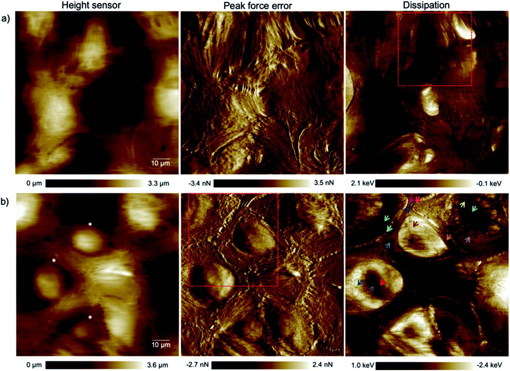 | ||
| Fig. 1 High resolution (1024 pixels × 1024 pixels) topography, force error and dissipation maps of (a) healthy mammary and (b) invasive ductal carcinoma cells at the 1st passage of our culturing process and 24 hours after transferring them onto plasma treated coverslips obtained in a CO2-independent growth medium by PFT-AFM. A setpoint force of 150 pN, an oscillation amplitude of 300 nm and a driving frequency of 0.25 kHz were used for imaging both types of cells. The colored arrows refer to locations where force vs. indentation curves were obtained. The asterisks mark cells that have been used for cell size and shape analysis (cf. the ESI, Table S1†). | ||
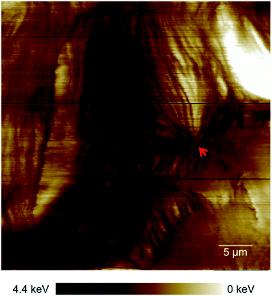 | ||
| Fig. 2 Enlarged area of the framed region in the dissipation image of Fig. 1a clearly exhibiting a centrosome (red arrow). | ||
Based on the averaged stiffness values we obtained from the derivative of the force vs. indentation curves on each substructure individually, we concluded that the relative absence of MTs as one of the most rigid filaments of the eukaryotic cell in IDCs could highly justify the higher deformability and softness of cancerous cells in comparison to their counterparts (see the ESI for details†). To support observations from AFM images we have obtained fluorescence images of healthy mammary epithelial cells and invasive ductal carcinoma (depicted in Fig. 3). Pancellular levels of F-actin labelled with TRITC-conjugated phalloidin (Fig. 3b) and pancellular levels of β-tubulin labelled with AF-488 labeled antibody (Fig. 3c) were quantified by widefield microscopy in which IDCs in comparison with healthy cells show a decrease in the average levels of MTs and F-actin. In PeakForce Tapping with a high driving frequency of 250 Hz and tip radius of approximately 40 nm sensing very delicate filaments such as F-actin with a diameter of 6–8 nm and intermediate filaments with a diameter of 10 nm depends on the area of imaging and they cannot be sensed all over the cell. MTs have the highest bending strength among all the three filaments of the cytoskeleton with a tubular structure with inner and outer diameters of 14 nm and 25 nm,27 respectively. In PFM-AFM images microtubules can be sensed all over the cell if existent in the structure. Although we stress that a decrease in the levels of F-actin has a significant influence on the overall mechanical properties of cancer cells compared to their counterparts, in atomic force microscopy measurements the dominant contribution to the stiffness sensed by the probe is the bending strength of structures.
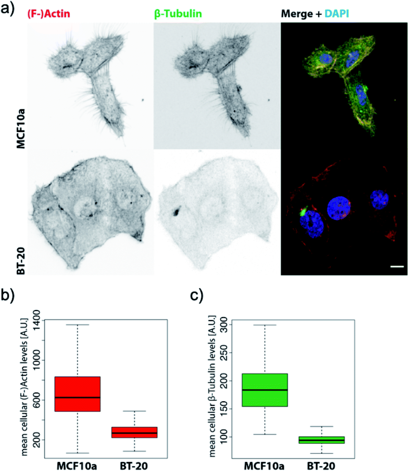 | ||
| Fig. 3 BT-20 cells show decreased levels of β-tubulin and impaired micro-tubule formation. (a) Representative confocal maximum Z-projections of MCF10a and BT-20 cells were stained with TRITC-conjugated phalloidin against (F-)actin and AF-488-conjugated monoclonal antibody against β-tubulin and counterstained with DAPI. Scale bar = 10 μm. (b) Pancellular levels of (F-)actin labelled with TRITC-conjugated phalloidin were quantified by widefield high-content screening microscopy. (c) Pancellular levels of β-tubulin labelled with AF-488 labeled antibody were quantified by widefield high-content screening microscopy. Measurements obtained by high-content screening microscopy were plotted with RStudio Version 1.2.1335, n-numbers = MCF10a: 7133, BT-20: 59129. Note: since the HBL-100 cell line harbors SV40 and is a near-normal epithelial cell line we preferred to use MCF10a which is a non-transformed mammary cell line46 as the control for widefield high-content screening microscopy of the levels of the filaments for comparison with invasive ductal carcinoma. However, we emphasize that the HBL-100 cell line is available as healthy mammary epithelial cells and is valid for AFM measurement comparison with BT-20. | ||
Directed motility is essential in cancer progression and metastasis. F-actin is the basic engine for gliding or crawling locomotion28 where migration requires the disruption of microtubules in the majority of cell types. The presence of the actin network, although lower in the cancer cell structure compared to its counterpart, and fewer MTs as depicted in Fig. 3a can facilitate cancer cell motility and help the infiltration and metastasis processes. Furthermore, the tightly packed parallel organization of actin bundles in the ductal carcinoma images (Fig. 1b) indicates the presence of fascin protein in cells.29 Fascin protein plays a critical role in cell migration, motility, and adhesion and cellular interactions and its overexpression plays a role in metastasis and is an important marker for breast cancer pathology.30
For the sake of penetrating deeper through the dense pack of microtubules in healthy mammary cells and sensing the deformability of cancerous cells we increased the peak force setpoint to 200 pN. Fig. 4 illustrates the spectroscopic and architectural differences between healthy (Fig. 4a) and cancerous mammary epithelial cells (Fig. 4b). The cells were at the 3rd passage of our culturing process and the images were obtained 72 hours after transferring them onto the plasma treated glass coverslip after feeding two times. For the healthy epithelial cells with a 50 pN higher force (Fig. 4a) than the force used to capture Fig. 1, the probe could penetrate enough to sense the dissipation of the nucleus under its supporting structures, yet the supporting structures such as MTs and the two membranes of the nucleus were sufficiently stiff to prevent the tip from sensing the smaller organelles inside the nucleus. Intermediate filaments which in general exhibit a wavy configuration (Fig. 4b) can adopt a variety of structural configurations and act as a “stress absorber” in eukaryotic cells.23 By allowing more time for the cell growth process in IDC, a more regular formation of intermediate filaments could be observed compared to that shown in Fig. 1b whereas formation of fewer MTs was still observed. More images supporting these observations can be found in Fig. S3 (ESI†). Cancer is a heterogeneous disease that shows distinct morphological features and clinical behaviors.1 These morphological differences that can be seen even in samples with the same histological type have been reported specifically for invasive ductal carcinoma and lead to their different responses to systemic therapy.1 We could vividly observe the differences in the shape of cells and the size of their nuclei among the images of IDC cells (cf.Fig. 1b and 4b) although they were from the same line but different passages. Furthermore, as can be seen in the topography image, the nuclei in healthy mammary cells have oval shapes whereas they have circular shapes of different sizes in IDC cells (Fig. 1 and 4). The MTs spontaneously align to form a nematic phase, forming linear microfilaments,31 which can cause the compression of the cell in one direction and give an oval shape to the soft nucleus that they support (can be seen in the healthy mammary cell images). Formation of fewer MTs in cancerous cells causes the nucleus to be relaxed in its natural circular shape (also refer to the ESI, Table S1†).
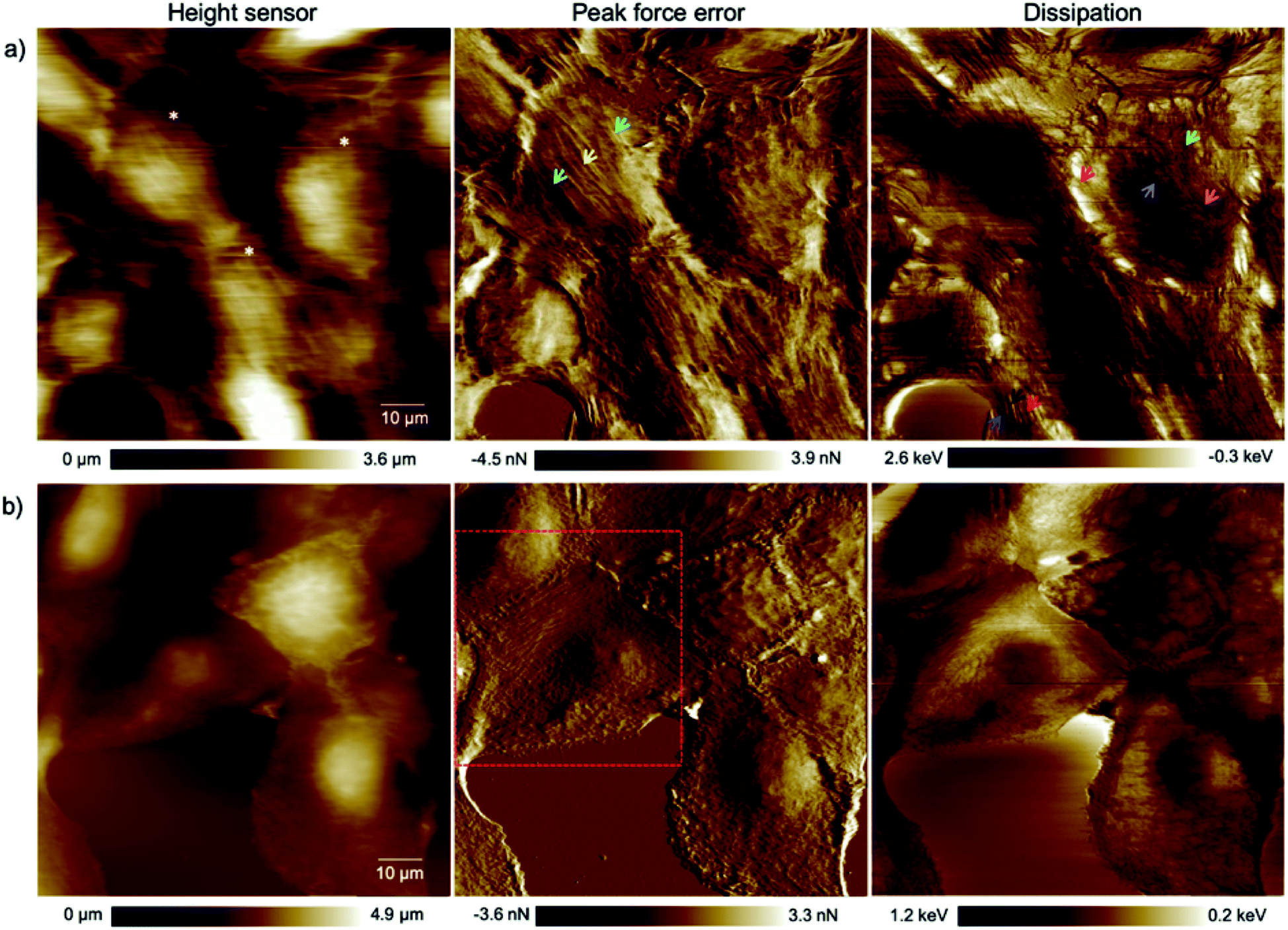 | ||
| Fig. 4 High resolution (1024 pixels × 1024 pixels) topography, force error and dissipation maps of (a) healthy mammary and (b) invasive ductal carcinoma cells at the 3rd passage of our culturing process and 72 hours after transferring them onto plasma treated coverslips obtained in a CO2-independent growth medium by PFT-AFM. A setpoint force of 200 pN, an oscillation amplitude of 300 nm and a driving frequency of 0.25 kHz were used for imaging both types of cells. The colored arrows refer to locations where force vs. indentation curves were obtained (see Fig. S1 and S2 in the ESI†). The asterisks mark cells that have been used for cell size and shape analysis (cf. the ESI, Table S1†). | ||
The invasive ductal carcinoma cells found the plasma treated coverslip to be a stable new site to settle down on, and the cells got completely attached to the new environment where they exhibited epithelial cell characteristics. As mentioned before, no epithelial–mesenchymal transition occurred that we could take into account for the alteration of the mechanical properties we observed. Thus, we concluded that the reason for the differences in the mechanical properties of ductal carcinoma and their higher deformability compared to that of their counterparts is an intrinsic change in the structure of the cells without any phenotypic shift from the epithelial to the mesenchymal type, as it has been reported that tumor cells that enter the circulation from metastatic lesions are not particularly more deformable than the originally injected population of tumor cells in a mouse breast tissue.32 The fluorescence images of the IDC cell line and healthy non transformed mammary epithelial cells as the control depict lowered levels of F-actin and MTs in IDCs compared to the control, illustrating the architectural changes of the epithelial cancer cells as an intrinsic alteration.
The smaller amount of MTs in IDC cells compared to their counterparts provided the opportunity to look directly into the mechanical properties of the nucleus as depicted in Fig. 5. We attribute the shape of the force curves in the current study to the hydrodynamic effects of the surrounding tip-cantilever system as a consequence of the high driving frequency of 250 Hz. As stated in ref. 33 the driving frequency in force spectroscopy should not exceed a certain ratio with respect to the cantilever resonance frequency. Nevertheless, we used such a high frequency in order to obtain a sufficiently high sampling rate for high-resolution AFM imaging. For comparison, a curve obtained with a low driving frequency of 20 Hz using standard force spectroscopy from the BT-20 nucleus region is depicted in Fig. S4 (ESI†). The various initial forces range from highly repulsive to highly attractive overall interactions that act on the cantilever during oscillation as can be seen in Fig. 5a. The average value obtained for the stiffness of the nucleus was 40 pN nm−1 (Fig. 5b). All curves which show the trajectory of the cantilever on the nucleus depict the typical hysteresis of viscoelastic materials with the trace above the retrace portion; however, in very soft regions that do not depict any prominent supportive filaments on top of the nucleus, a reversed hysteresis with the trace below and retrace above is observed (Fig. 5a, green curve) exhibiting a corresponding stiffness value of 8 pN nm−1. The filament network acts as an elastic material which provides resilience to the cells and the material remains stable when applying stress and upon unloading, eventually relaxing back to its original shape for moderate deformations. Due to the formation of considerably fewer filaments on top of the nucleus in cancerous cells, it acts as an utterly viscous material in which, upon unloading, the stress vanishes and the strain is at its peak starting to act on the cantilever, pushing the cantilever higher compared to the trace portion of the trajectory. On the other hand, due to the high overall attractive forces acting on the cantilever which are caused by the interactions between the negatively charged plasma treated substrate and positively charged silicon nitride tip in the slightly acidic medium, the trace portion shows a decrease in force while indenting deeper into the nucleus until the setpoint force was reached. The derivative of force vs. indentation shows a high peak at the end of the curve (Fig. 5b, green curve) sensing the stiff substrate at the lower turning point of the oscillation cycle. Furthermore, the electrostatic interaction between the tip and the cells' components was sufficiently high to cause an initial negative deflection of the cantilever in consequence of which some curves show negative values of force in the approach portion (cf. also the ESI†).
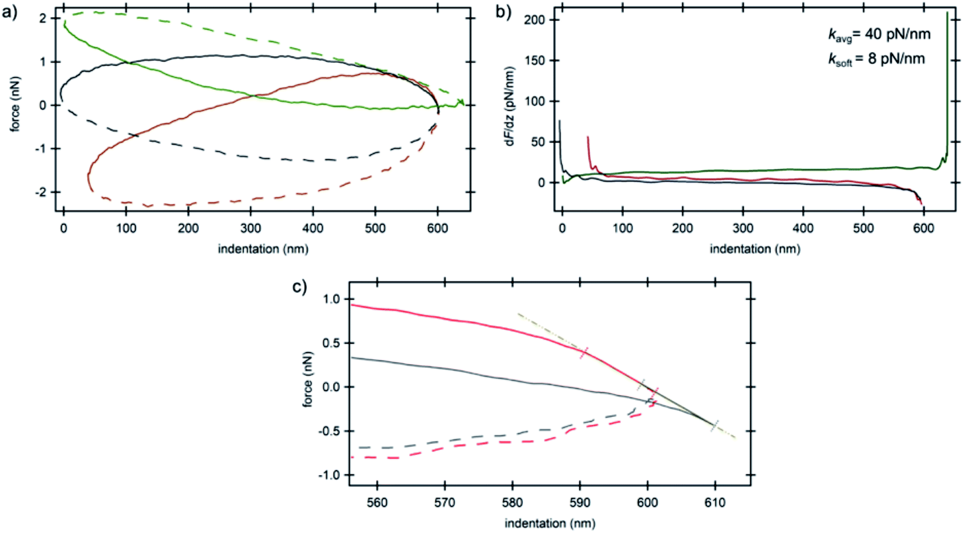 | ||
| Fig. 5 AFM spectroscopy results on the nucleus of invasive ductal carcinoma cells. (a) Force vs. indentation curves at three different locations (cf.Fig. 1b) and (b) corresponding stiffness vs. indentation curves. Solid lines are the trace portions of the oscillation cycle whereas the dashed lines are the retrace portions. (c) Force vs. indentation distribution curves at the lower turning point of the cantilever oscillation cycle obtained for the nucleus of invasive ductal carcinoma cells. Colors correspond to the arrow colors of Fig. 1b where the curves were obtained. The linear region shows attractive/repulsive attachment/detachment of the tip on/from the nucleus. Solid lines are the trace portions of the oscillation cycle whereas the dashed lines are the retrace portions. | ||
Observing cell–cell junctions in IDCs
Epithelial cells are held together by strong anchoring junctions such as (a) the adherens junction which associates with the actin filament complex and consists of the transmembrane protein E-cadherin and intracellular components, p120-catenin, β-catenin and α-catenin. These cell–cell junctions additionally have the biological roles of intracellular signaling and transcriptional processes.25,34 (b) Desmosomes provide the adhesive framework between the cytoskeleton and the plasma membrane and associate with the intermediate filament complex via cadherins, armadillo proteins and plakins. Desmosomes also take part in intercellular signaling pathways and proliferation.34 Furthermore, epithelial cells have occluding junctions between cells, the so called tight junctions, which associate the actin filament complexes with the transmembrane proteins occludin (OCLN) and claudin (CLDN1–25)34 that act as a gate by selectively limiting the passage of molecules and ions through the intercellular gap, as well as a fence which controls the diffusion of molecules between the apical and basolateral domains.35 The loss of some genes such as those encoding E-cadherin (helps in the formation of adherens junctions), OCLN and CLDN1, 2, and 7 (interfere in the formation of tight junctions) in infiltrating breast cancer has been reported,34 whereas E-cadherin loss was reported to be uncommon (around 35–50% of cases) in non-lobular cancers.36 Yet as illustrated in the dissipation image of Fig. 1b two anchoring junctions of desmosomes and adherens junctions and in the dissipation image of Fig. 3b the occluding tight junction can be clearly seen in IDCs even in a low amount. To discriminate between the various junctions observed in IDCs, we zoomed in to these regions and show an enlarged image in Fig. 6. In eukaryotic cells, a contractile bundle of actin filaments lies adjacent to the adhesion belt (continuous adherens junctions in epithelial cells), oriented parallel to the plasma membrane.26 Adherens junctions which connect bundles of actin filaments from cell to cell26 are apparent in region 1 (red encircled area) of Fig. 6a. Desmosomes which connect the bundles of intermediate filaments in adjacent cells almost perpendicular to the direction of actin filaments26 can be seen in our 2D system as shown in region 2 of Fig. 6a. Each tight junction is composed of a long row of transmembrane adhesion proteins present in the plasma membranes of both interacting cells. These proteins bind directly to each other to occlude the intercellular space.26 Occluding junctions which seal the cells tightly to each other are visible in region 1 of Fig. 6b. Furthermore, the cell showed a dense meshwork of filaments which is assumed to be lamellipodia (Fig. 6b) and a parallel configuration of actin filaments at the leading edge results in the formation of filopodia which promote forward movement. These features are highlighted in region 2 of Fig. 6b.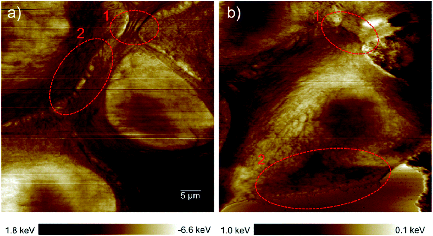 | ||
| Fig. 6 Types of cell junctions in IDCs. (a) Enlarged area of the dissipation image of Fig. 1b revealing adherens junctions highlighted in region 1 and desmosomes in region 2. (b) Enlarged area of the dissipation image of Fig. 3b revealing tight junctions highlighted in region 1 and lamellipodia and filopodia in region 2. The exact location where images (a) and (b) were obtained are marked by red dashed frames in the force error images of Fig. 1b and 3b, respectively. | ||
We observed the formation of cell–cell junctions that have the potential for signal transduction among neighboring cells like desmosomes and adherens junctions which have the ability to respond to various chemical and mechanical signals. These connections between cancerous cells with signal transducing ability keep the communication channels open among cells. This increases the possibility of cancerous cell collaboration in malignancy, infiltration or metastasis phenomena where we know that successive cell proliferation which increases the cell density causes secretion of specific soluble proteins that help cells to collaborate via the paracrine signaling pathway and migrate to a distant organ.37 Furthermore, it was reported in an earlier study that dissemination of cancer cells in metastasis occurs in clusters and a molecular mechanism in the most invasive cancer cells regulating cell–cell adhesion, cell–matrix adhesion, and immune evasion was observed.38
AFM can open up new pathways in the drug delivery research field
The capability of AFM measurements down to the micro- and even nano-scale with the need for only very small amounts of material and imaging very fine cell substructures and features such as actin bundles, MTs and centrosomes, tiny cell–cell junctions, filopodia, etc. promotes atomic force microscopy as an excellent characterization method for medical purposes in the vast field of drug delivery in particular for research on new methods of cancer treatment. One of the most important nuclear sub-organelles of eukaryotic cells which can be sensed by the probe is the nucleolus as shown in the 3D image in Fig. 7a. The image is a zoom-in on the nucleus where the nucleoli are apparent as white bumps in the topography. In optical micrographs in phase contrast, nucleoli have a higher optical density due to the dense packing of proteins and amino acids which is expected to be sensed as being stiffer in contrast to its periphery in AFM measurements. The mechanical properties of the cell cytoplasm, nuclear envelope and nucleolus were investigated with Brillouin microscopy.39 It has been shown that the nucleolus is stiffer than the nuclear envelope and surroundings and other studies on AFM confirm this observation.17 In the height image of the present study nucleoli appear brighter because of their greater stiffness and hence lower indentation depth of the tip into the nucleoli with respect to the surroundings. Cross-sectional profiles as indicated by the lines in Fig. 7a highlight the elevated features in Fig. 7b.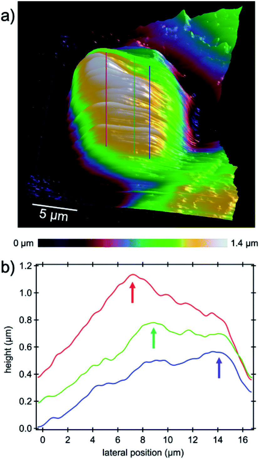 | ||
| Fig. 7 High-resolution PFT-AFM topography image of the cell nucleus. (a) Nucleoli inside the nucleus appear as white bumps. Lines indicate the location where cross-sectional profiles were drawn for clarification. (b) Cross-sectional profiles drawn through three nucleolar locations. Each profile was averaged over 15 adjacent lines corresponding to a width of 1.3 μm. Arrows highlight the elevated regions where nucleoli stand out from the nuclei. | ||
The main task of the nucleolus is the biogenesis of ribosomes (protein synthesis sites) and cell proliferation appears to be closely coordinated with nucleolar function as in mitosis the amount of cell constituents synthesized must be increased to assure the daughter cells' complement for survival and normal functioning.40 Increasing ribosome production for the sake of proliferation is a natural behavior of normal cells, although dysregulated ribosome biogenesis has been reported for years to be associated with cancer progression,41 where hypertrophic and irregularly shaped nucleoli as ribosome producers are found in a large number of cancer cells.40 In addition to mitosis, ribosomes play a role in stress response which increases the suspicion that initiation and progression of cancer are results of ribosome malfunction.41,42 Recent investigations into the nucleolus gave rise to a new approach in targeted cancer therapy which has been driven by (i) an increased understanding of the importance of ribosome biogenesis in malignant transformation; (ii) the discovery of the nucleolar control of p53; and (iii) the identification of the inhibition of ribosome biogenesis as a key feature of many chemo-therapeutic and anti-cancer drugs as concluded in the review of ref. 43. From the point of view that the nucleolus is the factory of ribosomes, our hypothesis is that targeting the nucleolus by means of charged nanocages could be highly efficient in cancer therapy as we know that accumulation of proteins inside nucleoli is because of the presence of positively charged amino acid sequences such as lysine44 and arginine in the nucleoli.45 High-resolution atomic force microscopy and structural analysis as demonstrated in this study could facilitate tracking of the carrier and drugs into the cell's nucleus and nucleolus, respectively, and verify successful delivery by means of charge detection and/or (sub-)structural changes.
Experimental section
Cell culturing
The epithelial mammary human cell line HBL-100 used in this work as normal cells and invasive ductal carcinoma BT-20 were received by our laboratory from CLS Cell Lines Service GmbH (Eppelheim, Germany). Cells were cultured at the first stage in a Petri flask in Dulbecco's modified Eagle's medium (DMEM) obtained from Merck KGaA (Darmstadt, Germany) containing 10% FBS (Merck KGaA, Darmstadt, Germany) and 1% penicillin/streptomycin (Carl Roth GmbH + Co. KG, Karlsruhe Germany). After approximately 72 hours Trypsin/EDTA (Merck KGaA, Darmstadt, Germany) was used to detach the cells, and they were subsequently centrifuged and transferred onto plasma treated glass coverslips inside plastic Petri dishes and incubated at 37 °C/5% CO2. For reaching a large confluence of cells on the coverslips, cells were fed 1–2 times before the AFM experiment, during which both samples were washed by PBS solution (Merck KGaA, Darmstadt, Germany) each time to change the culture medium.Cell staining
For the control we used the MCF10a healthy mammary epithelial cell line cultured in DMEM containing 10% FBS and 1% penicillin/streptomycin and seeded on 25 mm diameter coverslips. Since the HBL-100 cell line harbors SV40 and is a near-normal epithelial cell line we preferred to use MCF10a which is a non-transformed mammary cell line46 as the control for widefield high-content screening microscopy of the levels of the filaments for comparison with invasive ductal carcinoma. However, we emphasize that the HBL-100 cell line is available as healthy mammary epithelial cells and is valid for AFM measurement comparison with BT-20. MCF10a and BT-20 cells were stained with TRITC-conjugated phalloidin against F-actin (Merck KGaA, Darmstadt, Germany) and AF-488-conjugated monoclonal antibody against β-tubulin (Thermo Fisher Scientific, Waltham, MA) and counterstained with DAPI (Thermo Fisher Scientific). Prior to this, cells were fixed with 4% paraformaldehyde for 15 min and permeabilized for 10 minutes with 0.2% Triton in PBS. We blocked non-specific binding by means of 3% Bovine Serum Albumin (BSA) in PBS, followed by one hour of dye-loading with a ratio of 1![[thin space (1/6-em)]](https://www.rsc.org/images/entities/char_2009.gif) :1000 labels diluted in 3% blocking solution.
:1000 labels diluted in 3% blocking solution.
AFM imaging
Imaging and spectroscopy were performed with a Bruker Icon atomic force microscope (Bruker AXS, Santa Barbara, CA) in the Peak Force Tapping mode (PFT), in which the feedback loop controls the z-height of the piezo to keep the maximum cantilever deflection (force) constant during each oscillation cycle. Soft cantilevers with a nominal force constant of 0.01 N m−1 (triangular shaped microlevers, MLCT-BIO-DC-C, non-conductive silicon nitride from Bruker) were used for measuring the mechanical properties of the cells. The exact force constant was obtained by the thermal noise method.47 Typical values for the cantilever spring constant were in the range of 0.03–0.05 N m−1. The calibration of the deflection sensitivity was accomplished using a sapphire standard sample from Bruker by pushing the tip of the cantilever against the stiff surface and relating the deflection of the detection laser on the photosensitive diode to the motion of the z-piezo. The tips of the cantilevers have pyramid shapes with a tip radius R = 20 nm and a half-opening angle of α = 40°. The fundamental flexural resonant frequency of these cantilevers in deionized water was f0,flex ≈ 7 kHz. For imaging and spectroscopy of the cell samples by AFM we changed the medium to the L-15 Medium (Leibovitz), CO2-independent (Merck KGaA, Darmstadt, Germany), mixed with 10% FBS solution and 1% penicillin/streptomycin to decrease the odds of detachment or death of cells due to the change of the pH value of the culture medium. For imaging, PFT-AFM was operated with a digital resolution of 1024 × 1024-pixel for approximately 3 hours per image at a scan rate of 0.1 Hz for scan sizes of 93 × 93 μm2. Consequently, the lateral resolution obtained in each image was approximately 90 nm per pixel with an even smaller tip size. The maximum applied load exerted on the cells used for this study was set between 150 and 200 pN to minimize harm to the cells. It is known that the applied stress via the probe on the cells would be propagated through the cells and be reflected back from the substrate and affect the force that is sensed on the tip.18 Due to the viscoelastic shape of the force vs. distance curves, fitting the data using standard contact mechanics models is not possible; hence, we derived the maximum dynamic stiffness kmax of the substructures sensed by the tip using the classic definition of stiffness as a derivative of the force with respect to indentation. At this point we emphasize that the calibration of the PFT sync distance value was accomplished on a stiff material and the aim of this study was to measure the mechanical properties of very soft materials leading to a false trace–retrace partitioning. Thus, we corrected the force vs. distance curves based on the right trigger values (setpoint force). To this end, the z-position of the trigger value was identified as a sudden step in the force value in the retrace portion of the force curve and defined as the new transition point from the trace to the retrace portion. Accordingly, the z values were shifted with respect to the force values. For the sake of better visualization of substructure features in the topography images a first order levelling was necessary. Average stiffness values were calculated based on the derivative of at least three force curves for each identified feature inside the cell.Microscopy and image analysis
Confocal Z-stacks of MCF10a and BT-20 cells were acquired with a Leica TCS SPE confocal point scanner mounted on a Leica DMi8 stand and equipped with a 63×/1.30 ACS APO Oil CS 0.17/E,0.16 objective, a solid-state ruby laser module with 405 nm, 488 nm and 561 nm excitation lasers and a Leica SP detector. Acquired images were analyzed with Fiji (https://imagej.net/Fiji). For the analysis of pancellular levels of (F-)actin and β-tubulin, cells were imaged by high content microscopy with an Operetta automated imaging system (PerkinElmer, UK) equipped with a 20× long/0.45 NA objective, a xenon fiber optic as the light source, 360–400, 460–490 and 560–580 nm excitation filters and 410–480, 500–550 and 590–640 nm emission filters. Respective pancellular intensities were analyzed using Harmony software (PerkinElmer, UK) and mean values were plotted with RStudio Version 1.2.1335.48Conflicts of interest
There are no conflicts of interest to declare.Acknowledgements
The authors thank the Center of Smart Interfaces and the Deutsche Forschungsgemeinschaft (Sachbeihilfe DI 2176/2–1) for financial support. We further greatly appreciate the help of Robert Lehn from the Membrane Dynamics Group of the Biology Department of TU Darmstadt.References
- S. Badve, D. J. Dabbs, S. J. Schnitt, F. L. Baehner, T. Decker, V. Eusebi, S. B. Fox, S. Ichihara, J. Jacquemier, S. R. Lakhani, J. Palacios, E. A. Rakha, A. L. Richardson, F. C. Schmitt, P. H. Tan, G. M. Tse, B. Weigelt, I. O. Ellis and J. S. Reis-Filho, Mod. Pathol., 2011, 24, 157–167 CrossRef PubMed.
- R. Dent, M. Trudeau, K. I. Pritchard, W. M. Hanna, H. K. Kahn, C. A. Sawka, L. A. Lickley, E. Rawlinson, P. Sun and S. A. Narod, Clin. Cancer Res., 2007, 13, 4429–4434 CrossRef PubMed.
- K. R. Bauer, M. Brown, R. D. Cress, C. A. Parise and V. Caggiano, Cancer, 2007, 109, 1721–1728 CrossRef PubMed.
- A. E. McCart Reed, E. Kalaw, K. Nones, M. Bettington, M. Lim, J. Bennett, K. Johnstone, J. R. Kutasovic, J. M. Saunus, S. Kazakoff, Q. Y. Xu, S. Wood, O. Holmes, C. Leonard, L. E. Reid, D. Black, C. Niland, K. Ferguson, I. Gresshoff, A. Raghavendra, K. Harvey, C. Cooper, C. Liu, L. Kalinowski, A. S. Reid, M. Davidson, J. V. Pearson, N. Pathmanathan, G. Tse, D. Papadimos, R. Pathmanathan, G. Harris, R. Yamaguchi, P. H. Tan, S. B. Fox, S. A. O'Toole, P. T. Simpson, N. Waddell and S. R. Lakhani, J. Pathol., 2019, 247, 214–227 CrossRef CAS PubMed.
- A. A. Thike, P. Y. Cheok, A. R. Jara-Lazaro, B. Tan, P. Tan and P. H. Tan, Mod. Pathol., 2010, 23, 123–133 CrossRef CAS PubMed.
- M. D. Seal and S. K. Chia, Cancer J., 2010, 16, 12–16 CrossRef CAS PubMed.
- P. Gazinska, A. Grigoriadis, J. P. Brown, R. R. Millis, A. Mera, C. E. Gillett, L. H. Holmberg, A. N. Tutt and S. E. Pinder, Mod. Pathol., 2013, 26, 955–966 CrossRef PubMed.
- G. Bianchini, J. M. Balko, I. A. Mayer, M. E. Sanders and L. Gianni, Nat. Rev. Clin. Oncol., 2016, 13, 674–690 CrossRef CAS PubMed.
- B. Sousa, A. S. Ribeiro, A. R. Nobre, N. Lopes, D. Martins, C. Pinheiro, A. F. Vieira, A. Albergaria, R. Gerhard, F. Schmitt, F. Baltazar and J. Paredes, BMC Cancer, 2014, 14 Search PubMed.
- X. F. Dai, H. Y. Cheng, Z. H. Bai and J. Li, J. Cancer, 2017, 8, 3131–3141 CrossRef PubMed.
- A. J. Rice, E. Cortes, D. Lachowski, B. C. H. Cheung, S. A. Karim, J. P. Morton and A. D. Hernandez, Oncogenesis, 2017, 6, e352 CrossRef CAS PubMed.
- M. O. Krisenko, A. Cartagena, A. Raman and R. L. Geahlen, Biochemistry, 2015, 54, 60–68 CrossRef CAS PubMed.
- M. Plodinec, M. Loparic, C. A. Monnier, E. C. Obermann, R. Zanetti-Dallenbach, P. Oertle, J. T. Hyotyla, U. Aebi, M. Bentires-Alj, R. Y. H. Lim and C. A. Schoenenberger, Nat. Nanotechnol., 2012, 7, 757–765 CrossRef CAS PubMed.
- S. Suresh, Acta Biomater., 2007, 3, 413–438 CrossRef PubMed.
- M. E. Grady, R. J. Composto and D. M. Eckmann, J. Mech. Behav. Biomed. Mater., 2016, 61, 197–207 CrossRef CAS PubMed.
- A. Raman, S. Trigueros, A. Cartagena, A. P. Z. Stevenson, M. Susilo, E. Nauman and S. A. Contera, Nat. Nanotechnol., 2011, 6, 809–814 CrossRef CAS PubMed.
- L. Stuhn, A. Fritschen, J. Choy, M. Dehnert and C. Dietz, Nanoscale, 2019, 11, 13089–13097 RSC.
- P. D. Garcia and R. Garcia, Biophys. J., 2018, 114, 2923–2932 CrossRef CAS PubMed.
- M. Z. Nassef, S. Kopp, M. Wehland, D. Melnik, J. Sahana, M. Kruger, T. J. Corydon, H. Oltmann, B. Schmitz, A. Schutte, T. J. Bauer, M. Infanger and D. Grimm, Int. J. Mol. Sci., 2019, 20, 3156 CrossRef PubMed.
- M. Lekka, J. Bionanosci., 2016, 6, 65–80 CrossRef PubMed.
- J. Guck, S. Schinkinger, B. Lincoln, F. Wottawah, S. Ebert, M. Romeyke, D. Lenz, H. M. Erickson, R. Ananthakrishnan, D. Mitchell, J. Kas, S. Ulvick and C. Bilby, Biophys. J., 2005, 88, 3689–3698 CrossRef CAS PubMed.
- E. C. Faria, N. Ma, E. Gazi, P. Gardner, M. Brown, N. W. Clarke and R. D. Snooka, Analyst, 2008, 133, 1498–1500 RSC.
- M. L. Rodriguez, P. J. McGarry and N. J. Sniadecki, Appl. Mech. Rev., 2013, 65, 41 CrossRef.
- H. T. Morris and L. M. Machesky, Br. J. Cancer, 2015, 112, 613–620 CrossRef CAS PubMed.
- A. Hartsock and W. J. Nelson, Biochim. Biophys. Acta, Biomembr., 2008, 1778, 660–669 CrossRef CAS PubMed.
- B. Alberts, A. Johnson, J. Lewis, M. Raff, K. Roberts and P. Walter, Molecular Biology of the Cell, Garland Science, New York, 4th edn, 2002 Search PubMed.
- S. Ido, K. Kimura, N. Oyabu, K. Kobayashi, M. Tsukada, K. Matsushige and H. Yamada, ACS Nano, 2013, 7, 1817–1822 CrossRef CAS PubMed.
- T. J. Mitchison and L. P. Cramer, Cell, 1996, 84, 371–379 CrossRef CAS PubMed.
- J. C. Adams, Curr. Opin. Cell Biol., 2004, 16, 590–596 CrossRef CAS PubMed.
- S. Yamashiro, Y. Yamakita, S. Ono and F. Matsumura, Mol. Biol. Cell, 1998, 9, 993–1006 CrossRef CAS PubMed.
- D. J. Needleman, M. A. Ojeda-Lopez, U. Raviv, K. Ewert, H. P. Miller, L. Wilson and C. R. Safinya, Biophys. J., 2005, 89, 3410–3423 CrossRef CAS PubMed.
- J. S. Bagnall, S. Byun, S. Begum, D. T. Miyamoto, V. C. Hecht, S. Maheswaran, S. L. Stott, M. Toner, R. O. Hynes and S. R. Manalis, Sci. Rep., 2015, 5, 18542 CrossRef PubMed.
- C. A. Amo and R. Garcia, ACS Nano, 2016, 10, 7117–7124 CrossRef CAS PubMed.
- A. J. Knights, A. P. W. Funnell, M. Crossley and R. C. M. Pearson, Trends Cancer Res., 2012, 8, 61–69 CAS.
- N. A. Mack and M. Georgiou, Small GTPases, 2014, 5, 10 CrossRef PubMed.
- S. Doyle, A. J. Evans, E. A. Rakha, A. R. Green and I. O. Ellis, Radiology, 2009, 253, 51–55 CrossRef PubMed.
- H. Jayatilaka, P. Tyle, J. J. Chen, M. Kwak, J. Ju, H. J. Kim, J. S. H. Lee, P. H. Wu, D. M. Gilkes, R. Fan and D. Wirtz, Nat. Commun., 2017, 8, 15584 CrossRef CAS PubMed.
- K. J. Cheung, V. Padmanaban, V. Silvestri, K. Schipper, J. D. Cohen, A. N. Fairchild, M. A. Gorin, J. E. Verdone, K. J. Pienta, J. S. Bader and A. J. Ewald, Proc. Natl. Acad. Sci. U. S. A., 2016, 113, E854–E863 CrossRef CAS PubMed.
- G. Antonacci and S. Braakman, Sci. Rep., 2016, 6, 37217 CrossRef CAS PubMed.
- L. Montanaro, D. Trere and M. Derenzini, Am. J. Pathol., 2008, 173, 301–310 CrossRef CAS PubMed.
- J. Pelletier, G. Thomas and S. Volarevic, Nat. Rev. Cancer, 2018, 18, 51–63 CrossRef CAS PubMed.
- S. Boulon, B. J. Westman, S. Hutten, F. M. Boisvert and A. I. Lamond, Mol. Cell, 2010, 40, 216–227 CrossRef CAS PubMed.
- J. E. Quin, J. R. Devlin, D. Cameron, K. M. Hannan, R. B. Pearson and R. D. Hannan, Biochim. Biophys. Acta, Mol. Basis Dis., 2014, 1842, 802–816 CrossRef CAS PubMed.
- L. Lirussi, G. Antoniali, C. Vascotto, C. D'Ambrosio, M. Poletto, M. Romanello, D. Marasco, M. Leone, F. Quadrifoglio, K. K. Bhakat, A. Scaloni and G. Tell, Mol. Biol. Cell, 2012, 23, 4079–4096 CrossRef CAS PubMed.
- Y. R. Musinova, E. Y. Kananykhina, D. M. Potashnikova, O. M. Lisitsyna and E. V. Sheval, Biochim. Biophys. Acta, Mol. Cell Res., 2015, 1853, 101–110 CrossRef CAS PubMed.
- A. Vazquez-Martin, R. Colomer, J. Brunet, R. Lupu and J. A. Menendez, Cell Proliferation, 2008, 41, 59–85 CrossRef CAS PubMed.
- H. J. Butt and M. Jaschke, Nanotechnology, 1995, 6, 1–7 CrossRef.
- P. Zhang, A. K. Ludwig, F. D. Hastert, C. Rausch, A. Lehmkuhl, I. Hellmann, M. Smets, H. Leonhardt and M. C. Cardoso, Nucleus, 2017, 8, 548–562 CrossRef PubMed.
Footnote |
| † Electronic supplementary information (ESI) available. See DOI: 10.1039/c9na00021f |
| This journal is © The Royal Society of Chemistry 2019 |