 Open Access Article
The rational design of hierarchical MoS2 nanosheet hollow spheres sandwiched between carbon and TiO2@graphite as an improved anode for lithium-ion batteries†
Faze
Wang
 abc,
Fanggang
Li
a,
Maojun
Zheng
 *a,
Yanbo
Li
*b and
Li
Ma
d
aKey Laboratory of Artificial Structure and Quantum Control, Ministry of Education, Department of Physics and Astronomy, Shanghai Jiao Tong University, Shanghai, 200240, China. E-mail: mjzheng@sjtu.edu.cn
bInstitute of Fundamental and Frontier Sciences, University of Electronic Science and Technology of China, Chengdu, 610054, China. E-mail: yanboli@uestc.edu.cn
cWalter Schottky Institut, Physik Department, Technische Universität München, Garching 85748, Germany
dSchool of Chemistry and Chemical Technology, Shanghai Jiao Tong University, Shanghai, 200240, China
First published on 20th March 2019
Abstract
Molybdenum disulfide (MoS2) shows high capacity but suffers from poor rate capability and rapid capacity decay, which greatly limit its practical applications in lithium-ion batteries. Herein, we successfully prepared MoS2 nanosheet hollow spheres encapsulated into carbon and titanium dioxide@graphite, denoted as TiO2@G@MoS2@C, via hydrothermal and polymerization approaches. In this hierarchical architecture, the MoS2 hollow sphere was sandwiched by graphite and an amorphous carbon shell; thus, TiO2@G@MoS2@C exhibited effectively enhanced electrical conductivity and withstood the volume changes; moreover, the aggregation and diffusion of the MoS2 nanosheets were restricted; this advanced TiO2@G@MoS2@C fully combined the advantages of a three-dimensional architecture, hollow structure, carbon coating, and a mechanically robust TiO2@graphite support, achieving improved specific capacity and long-term cycling stability. In addition, it exhibited the high reversible specific capacity of 823 mA h g−1 at the current density of 0.1 A g−1 after 100 cycles, retaining almost 88% of the initial reversible capacity with the high coulombic efficiency of 99%.
Introduction
Lithium-ion batteries (LIBs) have attracted extensive attention as potential power sources for significant application in electric vehicles because of their long cycle life and high power density.1–3 Currently, graphite is predominantly used as an anode material for commercial LIBs. However, due to the relatively low theoretical capacity of graphite (around 372 mA h g−1), the commercial LIBs cannot meet the energy storage requirements for large-scale electric vehicles in the future.4,5 Thus, it is highly desirable to exploit alternative anode materials with higher capacity and excellent cycling stability. Transition metal oxides and sulfides as promising anode materials have shown striking electrochemical performance in LIBs.6–8 Among these alternatives, a two-dimensional (2D) layered material, molybdenum disulfide (MoS2), has received significant attention due to its open framework facilitating the insertion of Li+ reversibly; this leads to high reversible capacity.9–11 However, bare MoS2 electrodes exhibit poor rate capability and fast capacity fading caused by low conductivity, huge volume variation and aggregation during cycling.12–16 In addition to MoS2, TiO2 is considered as one of the most potential alternative anode materials owing to its excellent cycling stability, low cost and environmental friendliness. Several MoS2/TiO2 composites have been reported with improved electrochemical performance owing to their synergistic effects.17–25 When TiO2 and MoS2 are combined in a smart system, TiO2 with excellent chemical stability and low volume variation (<4%) is obtained,26 acting as a skeleton to effectively accommodate the strain of volume changes. Moreover, the high capacity of MoS2 can compensate the low specific capacity of TiO2. However, the MoS2 sheets present on the surface of TiO2 are still prone to strong restacking, and the intermediate polysulfides dissolve during repeated charge/discharge processes.27,28 Thus, the rational design of advanced hybrid materials of MoS2 and other functional components with complementary electrochemical properties is significantly desired to overcome these inherent obstacles.To date, significant efforts have been made to integrate MoS2 with carbonaceous materials (such as graphene, carbon nanotubes, amorphous carbon, carbon nanosheets, etc.),14,29–44 and all these composites exhibit better electrochemical performances as anode materials for LIBs due to the fully synergistic effect of nanostructured MoS2 and superior conductivity of highly flexible carbon materials. The carbon component could effectively accommodate the strain of volume change during cycling, prevent the aggregation and improve the electric conductivity.45,46 Despite the abovementioned success, there are still obstacles that hinder the further development of MoS2 because of the polysulfide shuttling effect causing capacity loss due to the lack of a top conductive protection layer. Therefore, it is highly required to develop an ideal hierarchical architecture with enhanced electrical conductivity and better electrode stability in which the synergistic effects of every component are manifested.
Herein, we designed template-assisted fabrication of hierarchical MoS2 nanosheet hollow spheres sandwiched between a graphite-coated TiO2 core and an amorphous carbon shell. Compared with the case of the simple core–shell TiO2@MoS2 nanostructure, the introduction of a graphite inter-layer and a carbon shell has two advantages: on the one hand, graphitic coating the mesoporous TiO2 hollow spheres provided a rapid pathway for lithium and electron transfer between the abundant interfaces of the sandwich-like MoS2/G/TiO2, accommodated the volume change and maintained the integrity of the hollow structure; on the other hand, the deposited carbon coating on the surface of the MoS2 nanosheets could prevent MoS2 from aggregation and the diffusion of sulfur while improving the electron conductivity and modifying the interface between the electrode/electrolyte. The synergistic effect of these three components and the hierarchical nanostructure endowed the carbon-coated TiO2@G@MoS2 hollow sphere with improved electrochemical properties for application in LIBs.
Results and discussion
The overall synthesis procedure of the triple-layer TiO2@G@MoS2 hollow nanosphere is illustrated in Fig. 1a, which involves four steps. First, SiO2 nanospheres were prefabricated as a core template based on the Stöber method.47Fig. 1b shows the scanning electron microscopy (SEM) image of the SiO2 nanosphere with the diameter of ca. 290 nm, and the spheres are significantly monodisperse, smooth and uniform. In the second step, amorphous TiO2 shells were deposited on the SiO2 nanospheres via a versatile kinetics-controlled coating method. Then, the as-prepared SiO2@TiO2 spheres were placed in a glucose solution and hydrothermally treated. In this step, the surface of the mesoporous TiO2 network was covered with decomposed glucose. Due to the catalytic effect of TiO2 nanoparticles, the glucose-coated SiO2@TiO2 spheres were transformed into SiO2@TiO2@graphitic carbon (SiO2@TiO2@G) core–shell nanospheres via calcination at 800 °C for 5 hours. The SEM images of the SiO2@TiO2@G samples show larger monodisperse spheres with the uniform diameter of 500 nm (Fig. 1c). The high-magnification SEM image clearly revealed that the surface consisted of primary small nanoparticles. Finally, the vertically oriented MoS2 nanosheets grew on the surface of SiO2@TiO2@G by an L-cysteine-assisted hydrothermal method. During the hydrothermal process, the MoO42− anions were reduced to MoS2 by S2− released from L-cysteine. Moreover, multifunctional groups (SH, NH2, and COO) of L-cysteine could guide the self-assembly growth of the MoS2 nanosheets on the surface of the carbon intermediate layer.29 The sample was further treated at 500 °C for 2 hours under a vacuum condition to obtain highly crystalline MoS2. Fig. 1d shows the typical SEM images of the as-synthesized SiO2@TiO2@G@MoS2 nanosphere structures, which indicates that the SiO2@TiO2@G spheres are uniformly coated with the MoS2 shell, and the diameter of these multi-layer core–shell spheres increases to ca. 600 nm. The high-magnification images revealed that the MoS2 shell was composed of interconnected vertically oriented ultrathin nanosheets. After the selective removal of SiO2 template by HF immersion, triple-layer TiO2@G@MoS2 hollow nanospheres were obtained (Fig. 1e).As shown in Fig. 2a, the interior space is revealed from an incomplete hollow sphere. The FESEM image of partly peeled TiO2@G@MoS2 hollow nanospheres clearly discloses that the hierarchical nanospheres consist of a mesoporous TiO2 core and a MoS2 nanosheet shell (Fig. 2b). The detailed core–shell hollow structure was further characterized by a transmission electron microscope (TEM). From a single core–shell nanosphere, it can be observed that the MoS2 nanosheet shell was uniformly attached to the surface of TiO2 (Fig. 2c). All the hollow spheres showed the uniform shell thickness of about 150 nm and an inner cavity of ∼300 nm, which was consistent with the diameter of the SiO2 templates. The HRTEM images show the lattice fringes of the MoS2 nanosheet structures. The thickness of the nanosheets was about several nanometers. The distance of the parallel lattice planes at the edge of the MoS2 nanosheet was about 6.5 Å, which corresponded to the d spacing of the (002) planes of MoS2 (Fig. 2d). To investigate the element distribution of MoS2, carbon and TiO2 in the TiO2@G@MoS2 hollow nanospheres, energy dispersive X-ray (EDX) spectroscopy was carried out (Fig. 2e). The elemental mapping images show that the Mo and S elements formed the shell and the core consisted of C and Ti with smaller diameter. These results directly demonstrated the hierarchical surface modification of the MoS2 nanosheet on graphite-coated TiO2 hollow spheres.
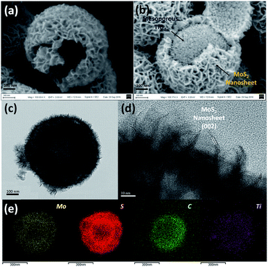 | ||
| Fig. 2 (a and b) SEM, (c) TEM and (d) HRTEM images of the TiO2@G@MoS2 hollow nanospheres. (e) EDX-elemental mapping images of Mo, S, C and Ti. | ||
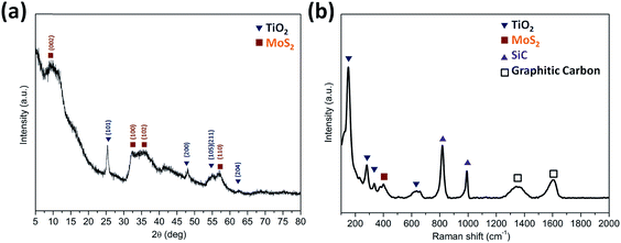
The XRD patterns (Fig. 3a) were acquired for the TiO2@G@MoS2 hollow nanospheres to obtain their crystallographic structure information. The diffraction peaks at 2θ = 14.3, 32.5, 36.0 and 58.5 correspond to the (002), (100), (102) and (110) planes of 2H–MoS2 (JCPDS no. 37-1492).48 In addition, the characteristic diffraction peaks assigned to (101), (200), (105), (111) and (204) of hexagonal TiO2 (JCPDS no. 21-1272) were present. Further insight into the nanostructure of TiO2@G@MoS2 was achieved by examination of its Raman spectrum (Fig. 3b). The characteristic Raman shifts at about 377 and 400 cm−1 expected for the E12g and A1g vibrational modes of hexagonal MoS2 were clearly observed.49 Moreover, the presence of the TiO2 core was confirmed by the Raman peaks emerging at 150, 282, 333 and 639 cm−1, which corresponded to the vibrational modes of the Ti–O bonds.50 The bands at 1357 and 1580 cm−1 were the typical D and G lines of graphitic carbon.51 Note that two strong bands emerging at 817 and 990 cm−1 can be assigned to SiC. In the annealing process, we predicted that the amorphous carbon would evaporate into the mesoporous TiO2 shell under a high vacuum condition; this would induce the formation of SiC. The existence of SiC would be beneficial for the improvement of stability because of its high mechanical strength.
X-ray photoelectron spectroscopy (XPS) was employed to characterize the chemical nature and bonding state of the TiO2@G@MoS2 hollow spheres. Fig. 4a displays the detailed XPS scans of the Mo, S and Ti binding energies. All the spectra were calibrated by a carbon 1s peak located at 284.50 eV. Moreover, two peaks at 229.3 and 228.4 eV were assigned to Mo 3d5/2 and Mo 3d3/2, respectively (Fig. 4b).33,52,53Fig. 4c shows the XPS spectrum of the S 2p region. In the high-resolution spectrum of Ti 2p (Fig. 4d), two peaks at 464.5 and 458.8 eV were attributed to Ti 2p1/2 and Ti 2p3/2, respectively. However, the Ti 2p peaks were relatively weak, indicating the full coverage of the MoS2 shell. The XPS results further confirmed the coexistence of MoS2 and TiO2 in the TiO2@G@MoS2 hierarchical structure, which agreed well with the XRD and Raman results.
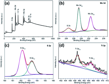 | ||
| Fig. 4 XPS spectra for the TiO2@G@MoS2 hollow nanospheres: (a) the survey spectrum and high-resolution (b) Mo 3d, (c) S 2p, and (d) Ti 2p spectra. | ||
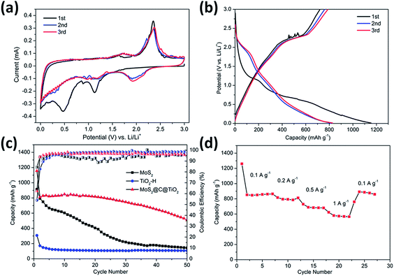
The electrochemical performance of the TiO2@G@MoS2 hollow structures as lithium-ion battery anodes was examined by assembling them into Li half-cells. Electrodes made up of the pure TiO2 hollow spheres and MoS2 nanoparticles were also prepared for comparison. Fig. 5a shows the cyclic voltammograms (CVs) of the initial three discharge/charge cycles at the scan rate of 0.1 mV s−1 within the potential window of 0.0–3.0 V (versus Li+/Li). In the first cycle, the two irreversible peaks at 1.127 and 0.473 correspond to the phase transition of MoS2, resulting from the intercalation of Li+ ions and the decomposition of MoS2 into Mo NPs, respectively.54–57
| MoS2 + xLi+ + xe− → LixMoS2 | (1) |
| LixMoS2 + (4 − x)Li+ + (4 − x)e− → Mo + 2Li2S | (2) |
These peaks disappeared in the second and third discharge processes because few amorphous MoS2 lattices were reformed after the first charge process (lithium extraction). After the first cycle, the electrode was mainly composed of Mo and S instead of initial MoS2.33 In the successive second and third discharge processes, a new broad peak appeared at 1.917 V, corresponding to the presence of a multistep lithium insertion mechanism, which involved the lithiation of TiO2 and S to form LixTiO2 and Li2S, respectively.29,58
| S + 2Li+ + 2e− ↔ LiS2 | (3) |
| TiO2 + xLi+ + xe− ↔ LixTiO2 | (4) |
In the charging process, there was an oxidation peak at 2.37 V with few changes in the subsequent sweeps, corresponding to the lithium extraction process.30,59 Moreover, a broad peak at 1.75 V could be attributed to the partial oxidation of Mo to Mo4+.56 These results illustrate that both MoS2 and TiO2 made a contribution to the charge–discharge capacity.
Fig. 5b shows the discharge–charge potential profiles of the TiO2@G@MoS2 hollow spheres in the 1st, 2nd and 3rd cycle at the current density of 0.1 A g−1 between 0.01 V and 3 V. In agreement with the CV results, two potential plateaus at 1.12 V and 0.47 V were observed in the first discharge process, which respectively corresponded to the phase transition of MoS2 and the conversion reaction process. In the subsequent discharge curves, the plateaus obtained in the first discharge disappeared, whereas a new plateau appeared at 1.8 V, which was attributed to a multi-step lithium insertion process. During the charging process, a conspicuous potential plateau at about 2.3 V was observed, which was also in accordance with the CV study.
The cycling performances of the TiO2@G@MoS2 hollow spheres as well as pure MoS2 and TiO2 hollow spheres were evaluated at the discharge current density of 0.1 A g−1, as shown in Fig. 5c. MoS2 delivered capacity fading from 914 mA h g−1 at the initial cycle to 143 mA h g−1 at the 50th cycle during discharge/charge cycles due to aggregation and pulverization. Moreover, the TiO2 hollow spheres exhibited excellent cycling stability; however, the capacity was only 105 mA h g−1 after 50 cycles. The lower charge capacities were mainly attributed to the lower theoretical capacity of TiO2. In contrast, the hierarchical hollow spheres showed significantly enhanced capacity and cycling stability. The initial discharge and charge specific capacities were 1330 and 908 mA h g−1, respectively, leading to the coulombic efficiency (CE) of 62%, which quickly stabilized at approximately 96% from the second cycle, being close to the coulombic efficiency of the TiO2 hollow spheres. Compared to the case of the MoS2 particles, the increased coulombic efficiency of the TiO2@G@MoS2 spheres was mainly attributed to their hollow structure since the hollow sphere architecture could provide large surface area and shorten the lithium ion diffusion path; moreover, the TiO2@G@MoS2 electrodes displayed an extraordinary capacity of 860 mA h g−1 in the first 20 cycles, which significantly exceeded that of either individual components. We suggest that the high theoretical capacity of the MoS2 shell, the superior cycling stability performance of the TiO2 hollow core and the excellent electric conductivity of the graphitic carbon interlayer are synergistically combined in the hierarchical TiO2@G@MoS2 composite electrode. Fig. 5d shows the rate capacity of triple-layer TiO2@G@MoS2 hollow sphere electrode at various current densities ranging from 0.1 to 1 A g−1. The specific discharge capacities of the composite were about 860, 780, 680, and 570 mA h g−1 upon cycling at 0.1, 0.2, 0.5, and 1 A g−1, respectively. When back to 0.1 A g−1, the capacity returned to 860 mA h g−1, indicating good rate performance of the TiO2@G@MoS2 composite.
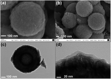
However, upon long-term discharge/charge processes, the cycling performance of the TiO2@G@MoS2 electrodes was still poor owing to the aggregation and pulverization of the MoS2 nanosheet shell, which contributed to most of the capacity as well as the highly conductive laminated layers to offer high interfacial contact areas and shorten the lithium ion diffusion paths.60,61 Therefore, the carbon thin shell was chosen as the top conductive protective layer to alleviate the volume changes, prevent the aggregation and pulverization of MoS2 and enhance the overall electronic conductivity of the electrode.62 The resorcinol–formaldehyde resin polymer shell was first deposited on the TiO2@G@MoS2 sphere. After carbonization of the polymer shell precursors under an ultrahigh vacuum at 600 °C for 2 hours, the core–shell carbon-coated TiO2@G@MoS2 hollow sphere electrode was obtained. It was observed that the nanospheres retained their spherical shape; moreover, after coating, their surface became smooth (instead of showing vertically orientated MoS2 nanosheets); this confirmed the uniform carbon coating (Fig. 6a and b). The TEM images demonstrate that the multiple-layer carbon coating TiO2@G@MoS2 sphere shows a similar hollow structure as TiO2@G@MoS2, but with a thin carbon shell coated on the surface of MoS2 (Fig. 6c). The curved MoS2 nanosheets were encapsulated into an amorphous carbon layer with a thickness of 20 nm (Fig. 6d). To determine the pore structure and surface area of the as-prepared TiO2@G@MoS2@C, the N2 adsorption/desorption test was conducted, as shown in Fig. S1.† The specific surface area was about 15.179 m2 g−1, and the main pore size was about 3.063 nm in diameter. To verify the content of the prepared sample, ICP-AES was used to determine the contents of Mo and Ti. The Mo and Ti contents in TiO2@G@MoS2@C were found to be 29.66% and 0.43%, respectively. The MoS2 and TiO2 contents were calculated to be 49.5% and 0.72%, respectively. The sulfur and carbon contents were analyzed by TGA. As shown in Fig. S2,† the weight loss occurring between 298 and 451 °C was mainly due to the oxidation of MoS2 to MoO3 and the removal of carbon. The remaining product after 500 °C was pure MoO3 with the weight percentage of 46.7%. The content of MoS2 was calculated to be 51.9%, which was approximately consistent with the ICP-AES result.
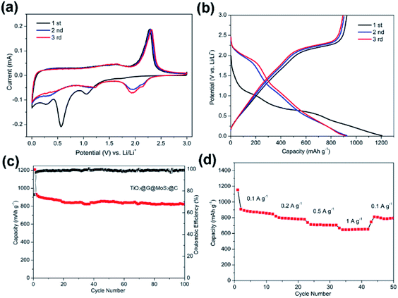
Fig. 7a shows the CV curves of carbon-coated TiO2@G@MoS2 electrode compared with those of the uncoated sample. The carbon-coated core–shell TiO2@G@MoS2 electrode had a lower anodic peak potential (2.31 V) and a higher cathodic peak potential (0.56 V), suggesting its better electrochemical reactivity and reversibility. The charge–discharge voltage profiles were obtained at the current density of 0.1 A g−1, indicating the initial discharge and charge capacities of 1208 and 933 mA h g−1, respectively, and the coulombic efficiency of 76.6% (Fig. 7b).
Fig. 7c shows the cycling performance of the carbon-coated TiO2@G@MoS2 hollow spheres at the current density of 0.1 A g−1 between 0.01 and 3.0 V. It exhibits enhanced capacity retention stability and high reversible capacity of 823 mA h g−1 even after 100 cycles, which is 88% of the capacity retention of the initial charge capacity. Moreover, the coulombic efficiency quickly stabilized at around 99% from the 4th cycle and was maintained in the following cycles. Compared to other TiO2/MoS2 composites, the carbon-coated TiO2@G@MoS2 hollow spheres showed higher electrochemical energy storage performances,17–25 especially high reversible capacity, which was attributed to the synergistic effects of all the components. The rate performance test was carried out for the carbon-coated TiO2@G@MoS2 hollow spheres to investigate their stability. The specific capacities of the composite were 850, 783, 700 and 650 mA h g−1 upon cycling at 0.1, 0.2, 0.5 and 1 A g−1, respectively. When the current density was reset to 0.1 A g−1, the capacity could still return to 850 mA h g−1; this confirmed the outstanding rate capability. We carried out the SEM and TEM characterization for the as-prepared electrodes of TiO2@G@MoS2@C and TiO2@G@MoS2 hollow spheres after cycling. As shown in Fig. S3,† the SEI films of the TiO2@G@MoS2 electrode were clearly thicker than those of the carbon-coated electrode (Fig. S3c and d†). Fig. S4† exhibits the TEM image of the as-prepared electrodes; the carbon hollow nanostructure was well preserved after 50 cycles, whereas the MoS2 particle was not observed on the carbon sphere surface for the TiO2@G@MoS2 hollow spheres sample; this was due to the detachment and diffusion of MoS2. Fig. S4c and d† show the TEM images of TiO2@G@MoS2@C, in which the hollow structure is well maintained, and the MoS2 particles distributed in the carbon coating shells can be still seen; this indicates the superior structural stability of TiO2@G@MoS2@C during long-term cycling.
The excellent cycling stability and remarkable rate capability of the hierarchical multiple-layer carbon-coated TiO2@G@MoS2 hollow spheres could be attributed to their unique structural advantages and synergistic effect. First, the graphitic carbon-coated mesoporous TiO2 hollow structure could effectively buffer the mechanical strain accompanying the lithium intercalation/exfoliation, alleviate huge volume variation of MoS2, and enhance the internal electronic conductivity of the hierarchical electrode.63 Second, the vertically oriented MoS2 laminated layers with high surface area provided a large electrode/electrolyte interface and shortened the diffusion paths for Li+ ions, thus improving the dynamic performance of Li+ storage.64,65 Third, the carbon-coated top layer prevented MoS2 from aggregation and pulverization, enhancing the electronic conductivity and contributing to the obvious improvement of long-term cycling stability.66,67 Based on the synergistic effect of all the aforementioned merits, the rationally designed carbon-coated TiO2@G@MoS2 core–shell hollow sphere exhibited remarkable electrochemical performance for lithium-ion storage.
Experimental
Synthesis of carbon-coated TiO2@G@MoS2 hollow nanospheres
Colloidal SiO2 nanospheres with a uniform diameter of 300 nm were fabricated by the Stöber method. For TiO2 coating, 0.2 g of the as-obtained SiO2 nanospheres was homogeneously dispersed in ethanol (150 mL). After this, ammonia solution (0.7 mL) was added to the suspension, and the mixture was stirred by a magnetic bar for 1 h. Then, tetrabutoxide titanate (TBOT, 2.0 mL) was added, and the reaction was proceeded at 45 °C for 24 h under continuous stirring. To produce the graphitic carbon-coated SiO2@TiO2 spheres, the SiO2@TiO2 core–shell structured spheres were homogeneously dispersed in a glucose solution (0.1 M, 15 mL) and hydrothermally treated at 180 °C for 2 h; this yielded the SiO2@TiO2@C spheres. Then, the amorphous TiO2/C shells could be converted to crystalline TiO2/graphitic carbon hybrid structures after annealing at 800 °C.To grow the hierarchical MoS2 shell on the graphitic carbon intermediate layer, 0.2 g of SiO2@TiO2@G sphere templates were dispersed in 60 mL of de-ionized water and 20 mL ethanol solution. Then, 0.6 g of sodium molybdate (Na2MoO4·2H2O) and 2.5 g of L-cysteine were added to the abovementioned solution. After ultrasonication, the reaction solution was then transferred to a Teflon-lined stainless steel autoclave and hydrothermally treated at 180 °C for 24 h. After etching of SiO2 by a 5% HF solution, 0.08 g of the as-obtained hollow nanospheres were dispersed in 2.82 mL of ethanol and 7.04 mL of deionized water, followed by the addition of 0.23 g cetyltrimethylammonium bromide (CTAB), 0.035 g resorcinol and 0.01 mL ammonia. After stirring at 35 °C for 30 min, 0.05 mL formalin was added to the dispersion. Then, the reaction was proceeded at 35 °C for 6 h under continuous stirring. The obtained polymer-coated TiO2@G@MoS2 was annealed at 600 °C for 2 h under a high vacuum atmosphere, and then, the carbon-coated TiO2@G@MoS2 hollow nanospheres were obtained.
Material characterization
The morphology information was determined by the FEI Sirion 200 scanning electron microscope (SEM) and the JEOL 2100F transmission electron microscope (TEM). Samples were characterized by X-ray diffraction (XRD, Rigaku Ultima IV X-ray Diffractometer) equipped with Cu Kα radiation. Surface composition of the sample was analyzed by X-ray photoelectron spectroscopy (XPS, AXIS ULTRA DLD, Kratos, Japan). Raman spectroscopy was conducted using the Renishaw inVia-reflex system at room temperature. A laser with the wavelength of 532 nm was used as the excitation source. Inductively coupled plasma-atomic emission spectrometry (ICP-AES, Thermo, iCAP7600) was used for detecting the concentrations of Mo and Ti ions. Thermogravimetric analysis (TGA) was carried out using a thermogravimetric analysis instrument (TGA, SDT Q600 V8.2 Build 100).Electrochemical measurements
The electrochemical tests were carried out in coin cells. The working electrode consisted of 80 wt% of active material, 10 wt% of conductive carbon black, and 10 wt% of polymer binder (polyvinylidene fluoride, PVDF). The electrolyte was 1 M LiPF6 in a mixture of ethylene carbonate (EC), dimethyl carbonate (DMC) and diethyl carbonate (DEC) (1![[thin space (1/6-em)]](https://www.rsc.org/images/entities/char_2009.gif) :
:![[thin space (1/6-em)]](https://www.rsc.org/images/entities/char_2009.gif) 1
1![[thin space (1/6-em)]](https://www.rsc.org/images/entities/char_2009.gif) :
:![[thin space (1/6-em)]](https://www.rsc.org/images/entities/char_2009.gif) 1 by volume). The typical mass loading of the active materials was about 1 mg cm−2. Lithium disc was used as both the counter electrode and the reference electrode. Cell assembly was carried out in an Ar-filled glove box with moisture and oxygen concentrations below 1.0 ppm. The charge–discharge tests were performed using the Land CT2001A battery test system. Cyclic voltammograms (CVs) were obtained using the CHI 660D electrochemical workstation.
1 by volume). The typical mass loading of the active materials was about 1 mg cm−2. Lithium disc was used as both the counter electrode and the reference electrode. Cell assembly was carried out in an Ar-filled glove box with moisture and oxygen concentrations below 1.0 ppm. The charge–discharge tests were performed using the Land CT2001A battery test system. Cyclic voltammograms (CVs) were obtained using the CHI 660D electrochemical workstation.
Conclusions
In summary, a hybrid architecture of carbon-coated TiO2@G@MoS2 has been successfully synthesized. The hierarchical MoS2 hollow spheres with high theoretical capacity were sandwiched by graphite and microporous carbon. The role of the carbon layer in the electrochemical energy storage performance was systematically investigated, and the key factors that controlled the capacity and cycling stability were identified. Due to the unique hierarchical core–shell nanostructure and the synergistic effect of every component, the rationally designed carbon-coated TiO2@G@MoS2 hollow sphere electrode exhibited high charge capacity and the cycling stability of 823 mA h g−1 at the current density of 100 mA g−1 after 100 cycles, retaining almost 88% of the initial reversible capacity with the high coulombic efficiency of 99%. Our study suggests a new mean for the synthesis of high-performance core/shell structure electrodes by the introduction of a carbon shell or interlayer for energy storage, which is expected to be widely extended to metal oxides or metal sulfides.Conflicts of interest
There are no conflicts to declare.Acknowledgements
This work was supported by the Natural Science Foundation of China (Grant no. 11174197 and 11574203).References
- V. Etacheri, R. Marom, R. Elazari, G. Salitra and D. Aurbach, Energy Environ. Sci., 2011, 4, 3243 RSC.
- F. Cheng, J. Liang, Z. Tao and J. Chen, Adv. Mater., 2011, 23, 1695 CrossRef CAS PubMed.
- B. Dunn and J. M. Tarascon, Science, 2011, 334, 928 CrossRef CAS PubMed.
- M. Armand and J. M. Tarascon, Nature, 2008, 451, 652 CrossRef CAS PubMed.
- J. B. Goodenough and K. S. Park, J. Am. Chem. Soc., 2013, 135, 1167 CrossRef CAS PubMed.
- J. Liu and X. W. Liu, Adv. Mater., 2012, 24, 4097 CrossRef CAS PubMed.
- M.-R. Gao, Y.-F. Xu, J. Jiang and S.-H. Yu, Chem. Soc. Rev., 2013, 42, 2986 RSC.
- P. Poizot, S. Laruelle, S. Grugeon, L. Dupont and J. M. Tarascon, Nature, 2000, 407, 496 CrossRef CAS PubMed.
- M. Chhowalla, H. S. Shin, G. Eda, L. J. Li, K. P. Loh and H. Zhang, Nat. Chem., 2013, 5, 263 CrossRef PubMed.
- X. Huang, Z. Zeng and H. Zhang, Chem. Soc. Rev., 2013, 42, 1934 RSC.
- H. Hwang, H. Kim and J. Cho, Nano Lett., 2011, 11, 4826 CrossRef CAS PubMed.
- J. Z. Wang, L. Lu, M. Lotya, J. N. Coleman, S. L. Chou, H. K. Liu, A. I. Minett and J. Chen, Adv. Energy Mater., 2013, 3, 798 CrossRef CAS.
- C. Zhang, Z. Wang, Z. Guo and X. W. Lou, ACS Appl. Mater. Interfaces, 2012, 4, 3765 CrossRef CAS PubMed.
- F. Xiong, Z. Cai, L. Qu, P. Zhang, Z. Yuan, O. K. Asare, W. Xu, C. Lin and L. Mai, ACS Appl. Mater. Interfaces, 2015, 7, 12625 CrossRef CAS PubMed.
- X. Zhou, L. J. Wan and Y. G. Guo, Nanoscale, 2012, 4, 5868 RSC.
- L. Hu, Y. Ren, H. Yang and Q. Xu, ACS Appl. Mater. Interfaces, 2014, 6, 14644 CrossRef CAS PubMed.
- R. Dai, A. Zhang, Z. Pan, A. M. Alenizi, A. A. Elzatahry, L. Hu and G. Zheng, Small, 2016, 12, 2792 CrossRef CAS PubMed.
- B. Chen, N. Zhao, L. Guo, F. He, C. Shi, C. He, J. Li and E. Liu, Nanoscale, 2015, 7, 12895 RSC.
- X. Xu, Z. Fan, S. Ding, D. Yu and Y. Du, Nanoscale, 2014, 6, 5245 RSC.
- X. Li, W. Li, M. Li, P. Cui, D. Chen, T. Gengenbach, L. Chu, H. Liu and G. Song, J. Mater. Chem., 2014, 3, 2762 RSC.
- X. Zhu, C. Yang, F. Xiao, J. Wang and X. Su, New J. Chem., 2014, 39, 683 RSC.
- M. Mao, L. Mei, D. Guo, L. Wu, D. Zhang, Q. Li and T. Wang, Nanoscale, 2014, 6, 12350 RSC.
- B. Guo, K. Yu, H. Fu, Q. Hua, R. Qi, H. Li, H. Song, S. Guo and Z. Zhu, J. Mater. Chem. A, 2015, 3, 6392 RSC.
- B. Chen, E. Liu, F. He, C. Shi, C. He, J. Li and N. Zhao, Nano Energy, 2016, 26, 541 CrossRef CAS.
- J. Y. Liao, B. D. Luna and A. Manthiram, J. Mater. Chem. A, 2015, 4, 801 RSC.
- M. Wagemaker, G. J. Kearley, A. A. van Well, H. Mutka and F. M. Mulder, J. Am. Chem. Soc., 2003, 125, 840 CrossRef CAS PubMed.
- C. Luo, Y. Xu, Y. Zhu, Y. Liu, S. Zheng, A. Langrock and C. Wang, ACS Nano, 2013, 7, 8003 CrossRef CAS PubMed.
- J. Liu, P. Kopold, C. Wu, P. A. V. Aken, J. Maier and Y. Yu, Energy Environ. Sci., 2015, 8, 3531 RSC.
- K. Chang and W. Chen, ACS Nano, 2011, 5, 4720 CrossRef CAS PubMed.
- J. Xiao, X. Wang, X. Q. Yang, S. Xun, G. Liu, P. K. Koech, J. Liu and J. P. Lemmon, Adv. Funct. Mater., 2011, 21, 2840 CrossRef CAS.
- S. H. Choi, Y. N. Ko, J.-K. Lee and Y. C. Kang, Adv. Funct. Mater., 2015, 25, 1780 CrossRef CAS.
- K. Chang, D. Geng, X. Li, J. Yang, Y. Tang, M. Cai, R. Li and X. Sun, Adv. Energy Mater., 2013, 3, 839 CrossRef CAS.
- X. Cao, Y. Shi, W. Shi, X. Rui, Q. Yan, J. Kong and H. Zhang, Small, 2013, 9, 3433 CrossRef CAS PubMed.
- X. Xie, Z. Ao, D. Su, J. Zhang and G. Wang, Adv. Funct. Mater., 2015, 25, 1393 CrossRef CAS.
- X.-Y. Yu, H. Hu, Y. Wang, H. Chen and X. W. Lou, Angew. Chem., Int. Ed., 2015, 127, 7503 CrossRef.
- X. Li, J. Zhang, R. Wang, H. Huang, C. Xie, Z. Li, J. Li and C. Niu, Nano Lett., 2015, 15, 5268 CrossRef CAS PubMed.
- Y. Shi, Y. Wang, J. I. Wong, A. Y. S. Tan, C.-L. Hsu, L.-J. Li, Y.-C. Lu and H. Y. Yang, Sci. Rep., 2013, 3, 2169 CrossRef PubMed.
- S. Ding, J. S. Chen and X. W. Lou, Chem.–Eur. J., 2011, 17, 13142 CrossRef CAS PubMed.
- Y. Fang, Y. Lv, F. Gong, A. A. Elzatahry, G. Zheng and D. Zhao, Adv. Mater., 2016, 28, 9385 CrossRef CAS PubMed.
- J. Wang, C. Luo, T. Gao, A. Langrock, A. C. Mignerey and C. Wang, Small, 2015, 11, 473 CrossRef CAS PubMed.
- K. Chang, W. Chen, L. Ma, H. Li, H. Li, F. Huang, Z. Xu, Q. Zhang and J.-Y. Lee, J. Mater. Chem., 2011, 21, 6251 RSC.
- C. Zhu, X. Mu, P. A. van Aken, Y. Yu and J. Maier, Angew. Chem., Int. Ed., 2014, 53, 2152 CrossRef CAS PubMed.
- H. Jiang, D. Ren, H. Wang, Y. Hu, S. Guo, H. Yuan, P. Hu, L. Zhang and C. Li, Adv. Mater., 2015, 27, 3687 CrossRef CAS PubMed.
- J. Zhou, J. Qin, X. Zhang, C. Shi, E. Liu, J. Li, N. Zhao and C. He, ACS Nano, 2015, 9, 3837 CrossRef CAS PubMed.
- B. Jiang, C. Han, B. Li, Y. He and Z. Lin, ACS Nano, 2016, 10, 2728–2735 CrossRef CAS PubMed.
- B. Jiang, Y. He, B. Li, S. Zhao, S. Wang, Y.-B. He and Z. Lin, Angew. Chem., Int. Ed., 2017, 56, 1869–1872 CrossRef CAS PubMed.
- W. Stöber, A. Fink and E. Bohn, J. Colloid Interface Sci., 1968, 26, 62 CrossRef.
- S. Liang, J. Zhou, J. Liu, A. Pan, Y. Tang, T. Chen and G. Fang, CrystEngComm, 2013, 15, 4998 RSC.
- H. Liu, D. Su, R. Zhou, B. Sun, G. Wang and S. Z. Qiao, Adv. Energy Mater., 2012, 2, 970 CrossRef CAS.
- X. Chen, L. Liu, P. Y. Yu and S. S. Mao, Science, 2011, 331, 746 CrossRef CAS PubMed.
- A. C. Ferrari and J. Robertson, Phys. Rev. B: Condens. Matter Mater. Phys., 2008, 61, 14095 CrossRef.
- K. K. Liu, W. Zhang, Y. H. Lee, Y. C. Lin, M. T. Chang, C. Y. Su, C. S. Chang, H. Li, Y. Shi and H. Zhang, Nano Lett., 2012, 12, 1538 CrossRef CAS PubMed.
- Y. H. Chang, C. T. Lin, T. Y. Chen, C. L. Hsu, Y. H. Lee, W. Zhang, K. H. Wei and L. J. Li, Adv. Mater., 2013, 25, 756 CrossRef CAS PubMed.
- T. Stephenson, Z. Li, B. Olsen and D. Mitlin, Energy Environ. Sci., 2014, 7, 209 RSC.
- M. Lin, J. Ye, W. Chen, D. Chen and J. Y. Lee, Nano Energy, 2014, 10, 144 CrossRef.
- X. Fang, X. Yu, S. Liao, Y. Shi, Y. S. Hu, Z. Wang, G. D. Stucky and L. Chen, Microporous Mesoporous Mater., 2012, 151, 418 CrossRef CAS.
- M. Mao, L. Mei, D. Guo, L. Wu, D. Zhang, Q. Li and T. Wang, Nanoscale, 2014, 6, 12350 RSC.
- X. Jiang, X. Yang, Y. Zhu, H. Jiang, Y. Yao, P. Zhao and C. Li, J. Mater. Chem. A, 2014, 2, 11124 RSC.
- Y. Sun, J. Zhu, L. Bai, Q. Li, X. Zhang, W. Tong and Y. Xie, Inorg. Chem. Front., 2014, 1, 58 RSC.
- X. Wang, Z. Zhang, Y. Chen, Y. Qu, Y. Lai and J. Li, J. Alloys Compd., 2014, 600, 84 CrossRef CAS.
- S. Ding, D. Zhang, J. S. Chen and X. W. Lou, Nanoscale, 2012, 4, 95 RSC.
- Z. Cai, L. Xu, M. Yan, C. Han, L. He, K. M. Hercule, C. Niu, Z. Yuan, W. Xu, L. Qu, K. Zhao and L. Mai, Nano Lett., 2015, 15, 738 CrossRef CAS PubMed.
- S. Zhao, Z. Wang, Y. He, B. Jiang, Y. Harn, X. Liu, F. Yu, F. Feng, Q. Shen and Z. Lin, ACS Energy Lett., 2017, 2, 111–116 CrossRef CAS.
- L. Zhang, H. B. Wu, Y. Yan, X. Wang and X. W. Lou, Energy Environ. Sci., 2014, 7, 3302 RSC.
- L. Zhang and X. W. Lou, Chem.–Eur. J., 2014, 20, 5219 CrossRef CAS PubMed.
- A. P. Tiwari, H. Yoo, J. Lee, D. Kim, J. H. Park and H. Lee, Nanoscale, 2015, 7, 11928 RSC.
- D. Xie, X. Xia, Y. Zhong, Y. Wang, D. Wang, X. Wang and J. Tu, Adv. Energy Mater., 2017, 7, 1601804 CrossRef.
Footnote |
| † Electronic supplementary information (ESI) available. See DOI: 10.1039/c9na00019d |
| This journal is © The Royal Society of Chemistry 2019 |


