
 Open Access Article
 This Open Access Article is licensed under a Creative Commons Attribution-Non Commercial 3.0 Unported Licence
Ultra-stable pulse generation in ytterbium-doped fiber laser based on black phosphorus†
Tao
Wang‡
a,
Xiaoxi
Jin‡
a,
Jie
Yang‡
b,
Jian
Wu
*ad,
Qiang
Yu
b,
Zhenghui
Pan
b,
Hanshuo
Wu
a,
Junzi
Li
c,
Rongtao
Su
a,
Jiangming
Xu
a,
Kai
Zhang
b,
Tingchao
He
 *c and
Pu
Zhou
*a
*c and
Pu
Zhou
*a
aCollege of Advanced Interdisciplinary Studies, National University of Defense Technology, Changsha, 410073, China. E-mail: wujian15203@163.com; zhoupu203@163.com
bi-Lab, Suzhou Institute of Nano-Tech and Nano-Bionics, Chinese Academy of Sciences, Suzhou 215123, China
cCollege of Physics and Energy, Shenzhen University, Shenzhen 518060, China. E-mail: tche@szu.edu.cn
dCAS Key Laboratory of Nano-Bio Interface, Suzhou Institute of Nano-Tech and Nano-Bionics, Chinese Academy of Sciences, Suzhou 215123, China
First published on 4th December 2018
Abstract
We demonstrated a high-quality black phosphorus (BP) crystal fabricated via a modified electrochemical delamination exfoliation process. Employing the nonlinear transmittance method and Z-scan technique, the nonlinear optical properties of BP were characterized. Based on the saturable absorber (SA) of BP, we designed a passively Q-switched ytterbium (Yb)-doped fiber laser operating at 1.06 μm. Additionally, the pulse laser could operate stably for at least 69 days. These experimental results indicate that the modified BP is an ultra-stable and promising optical modulation material for ultrashort pulse generation in Yb-doped fiber lasers.
1. Introduction
Recently, as saturable absorbers (SAs), two-dimensional (2D) materials such as graphene,1 carbon nanotubes,2 transition-metal dichalcogenides (TMDs),3,4 and topological insulators (TIs)5–7 have attracted much attention to generate pulse lasers. The passive ways based on SA to produce pulse lasers have the advantages of low cost, easy implementation and compactness.8 However, most 2D materials have some shortcomings that seriously limit their practical application. For example, graphene has a zero band gap,9 which limits its applications where strong interactions between the laser and material are needed, although it possesses wide-band absorption and ultrafast recovery time. TMDs have a wide band gap, but may be only suitable for absorption in the visible wavelength. Black phosphorus (BP) is another potential SA for ultra-short pulse generation, which is regarded as the most thermo-dynamically stable allotrope.10 BP has a direct bandgap, which depends on the number of layers and ranges from 0.3 eV in the bulk state to 2.0 eV in the monolayer state.11–13 This can greatly enhance the interactions between light and BP14 at wavelengths from the visible to near-infrared region. Therefore, BP is an excellent SA for wide-band ultrafast photonics application.Since the first BP-based SA (BP-SA) deposited around a microfiber was proposed,15 there has been much progress in the field of BP-based pulse laser generation.16–21 BP-SA can be manufactured via liquid phase exfoliation technology14 or the mechanical exfoliation method.22 Zhang et al. reported few-layer selenium-doped black phosphorus with high quality and low cost in 2017.23 However, avoiding oxidation and preventing optical damage to the BP-SA still limit its application.24 Research on the stability of BP-SA is scarce. M. Hisyam et al. observed a mode-locked pulse based on BP at 20 minute intervals for 80 minutes.16 Under 816 mW pump power, the peak amplitudes of the spectrum varied within ±1 dB with a signal to noise ratio (SNR) of 47 dB.16 Thus, further enhancing the long-term stability of BP is another obstacle that needs to be addressed.
Herein, BP was fabricated via a modified electrochemical delamination exfoliation process.25 Based on the BP-SA device, we demonstrated a passively Q-switched Yb-doped fiber laser operating in the 1.06 μm region. A stable Q-switched pulse with a maximum output power of 12.6 mW and a slope efficiency of 11.1% WAS achieved. The laser could operate stably for at least 69 days, and its output properties were recorded in detail. To the best of our knowledge, our laser exhibits the best stability compared with that reported to date.
2. Sample preparation and characterization of black phosphorus saturable absorber
High quality and large-size BP bulk crystals were produced via a modified gas-phase transformation method23,26 (details in ESI section 1†).For the exfoliation process, the non-oxidative electrochemical delamination strategy exfoliation process was performed through electrochemical engineering in non-aqueous electrolytes25 using a two-electrode system. About several hundred mg of bulk BP crystals was used as the cathode, and a piece of platinum foil was used as the anode. The electrolyte was made by dissolving tetra-n-butyl-ammonium bisulfate (TBA·HSO4) in anhydrous deoxygenated propylene carbonate with the concentration of 0.1 M. The electrolysis voltage was set at −30.0 V at the beginning of the delamination and was turned down to −10 V after 20 min.
For further characterization, some treatments were needed. The exfoliated BP was centrifuged at 8000 rpm for 5 min and washed with anhydrous propylene carbonate and isopropyl alcohol (IPA) twice. Afterwards, a moderate amount of as-washed BP flakes were dispersed into anhydrous IPA by mild sonication for 15 min. Finally, the supernatant was decanted for further fabrication and characterization (Fig. 1(a)).
 | ||
| Fig. 1 Characteristics of the few-layer BP crystals synthesized via the electrochemical delamination exfoliation method: (a) digital image of the few-layer BP flakes ink, (b) atomic force microscopy (AFM) image of a typical few-layer BP flake from the crystal on a silicon substrate, (c) scanning electron microscopy (SEM) image of a typical few-layer BP flake from the crystal on a silicon substrate, (d) typical transmission electron microscopy (TEM) image of a BP flake, (e) high-resolution TEM image of a BP flake, (f) TEM neutron diffraction image of a BP flake, (g) Raman spectrum of the BP, (h) X-ray diffraction (XRD) pattern of the BP sample, which confirms its high crystallinity and (i) X-ray photoelectron spectroscopy (XPS) spectrum of the BP sample. | ||
The atomic force microscopy (AFM) image of a typical sample and the associated height variations along the marked lines are depicted in Fig. 1(b). The thickness was measured to be 7–14 nm. The dominant BP film was observed using a Hitachi® S-4800 scanning electron microscope (SEM). The corresponding SEM image of a typical few-layer BP flake from the crystal on a silicon substrate is shown in Fig. 1(c). The microstructure and chemical composition of the BP crystal were thoroughly probed using a Tecnai® G2 F20 S-Twin transmission electron microscope (TEM), as shown in Fig. 1(d–f). A high-resolution TEM image of the micro-flake is shown in Fig. 1(e), which illustrated a clear lattice fringe with an interplanar space of 0.33 nm. As shown in Fig. 1(f), the selected area electron diffraction pattern can be well indexed to an orthorhombic structure and the zone axis was determined as the [010] direction. In Fig. 1(g), the identity of the BP-SA was also verified by Raman spectroscopy, which discloses three characteristic vibration modes located at 362 cm−1 (Ag1), 437.5 cm−1 (B2g), and 466 cm−1 (Ag2). The integrated intensity ratio Ag1/Ag2 is 0.41, which is greater than 0.20 and in the range of 0.40–0.60, indicating its low oxidation level.27 The crystal structure of the BP-SA sample was characterized via X-ray diffraction (XRD). The XRD image exhibits high diffraction peaks in Fig. 1(h). The strong intensity diffraction peaks at 17.08°, 34.28°, and 52.48° correspond to the (020), (040), and (060) planes, respectively, which indicate that the BP sample possesses an orthorhombic structure with high crystalline quality. The X-ray photoelectron spectroscopy (XPS) spectrum of the BP crystal is shown in Fig. 1(i). The high-resolution XPS reveals that the band associated with P2p appears at about 130 eV, which can be divided into P2p1/2 (130.5 eV) and P2p3/2 (129.5 eV), as the key feature of crystalline BP. Moreover, the oxidized phosphorus peaks near 132 eV disappear in the XPS spectra, indicating that the BP is well-prepared and free from oxidation during the exfoliation process.
3. Results and discussions
3.1 Nonlinear optical properties of black phosphorus
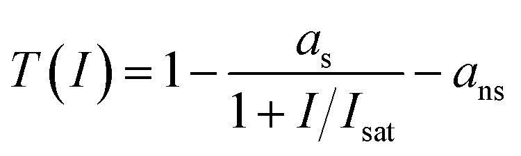
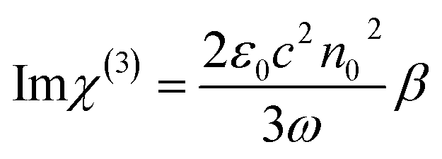
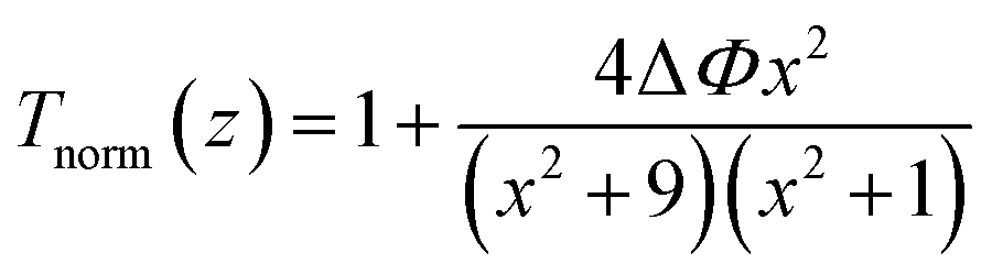
To prepare the SA film, the vacuum filtration method was used. The exfoliated BP solution was deposited onto a piece of filter membrane via vacuum filtration. Finally, the sample was dried in a vacuum oven at 50 °C for 20 min, and the thin film was peeled off with tweezers. The fiber ferrule with the deposited BP-SA was then connected with a clean one via a fiber ferrule adapter, forming an SA ready for use in the fiber laser (see details in Fig. S1–S2 in the ESI†).Fig. 2(a) shows the linear transmittance spectrum of the BP film in the 800–1500 nm spectral range, which was measured using a home-built light source system. The transmittance was about 60% at 1064 nm.
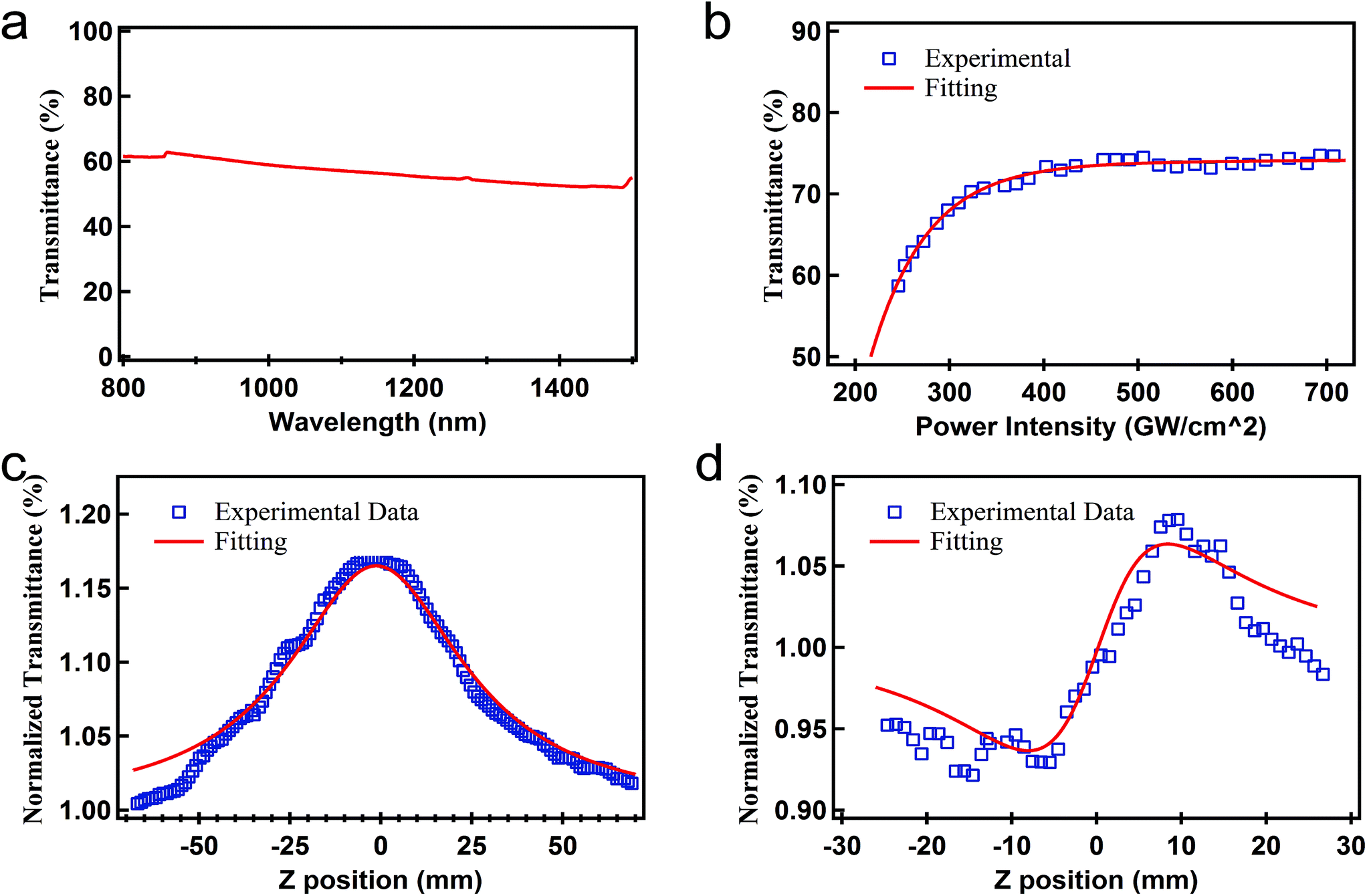 | ||
| Fig. 2 (a) Optical transmittance for the BP, (b) relation between the incident intensity and transmittance of the BP crystal, (c) open Z-scan curve for the BP crystal, and (d) close/open Z-scan curve for the BP crystal. | ||
The nonlinear optical transmittance of BP was characterized under different input power intensities at the wavelength of 1060 nm (1000 Hz, 100 fs), as depicted in Fig. 2 (b). The relevant curve can be fitted by the following formula:
 | (1) |
The open-aperture Z-scan results are shown in Fig. 2(c), and the normalized transmittance can be fitted by the following formula:
 | (2) |
 | (3) |
 | (4) |
 | (5) |
3.2 Laser performance of BP and stability test
The experimental setup for the Yb-doped all-fiber ring laser based on BP-SA is depicted in Fig. 3(a). The fiber laser was pumped by a single-mode laser diode centered at 976 nm with a maximum pump output of 780 mW. The pump light was coupled in the ring cavity via a broadband 976/1064 nm wavelength division multiplexing. The gain medium was a piece of 2 m-long Yb-doped fiber, with a core diameter of 6 μm and a cladding diameter of 125 μm, and its absorption coefficient was about 12 dB m−1 and NA 0.12. A polarization insensitive optical isolator centering at 1064 nm was inserted into the ring cavity to ensure unidirectional light propagation. A band-pass optical filter was adopted after the PI-ISO. To optimize the polarization state inside the cavity, a polarization controller was used. The SA was adsorbed on a fiber ferrule adapter. The BP-SA was adopted in the ring cavity to induce Q-switched operation. A coupler with 20% output was employed to output the intra-cavity energy. The output power was further divided into three parts to enable the simultaneous measurement of output power (15%), optical spectrum (15%) and pulse characteristic (70%).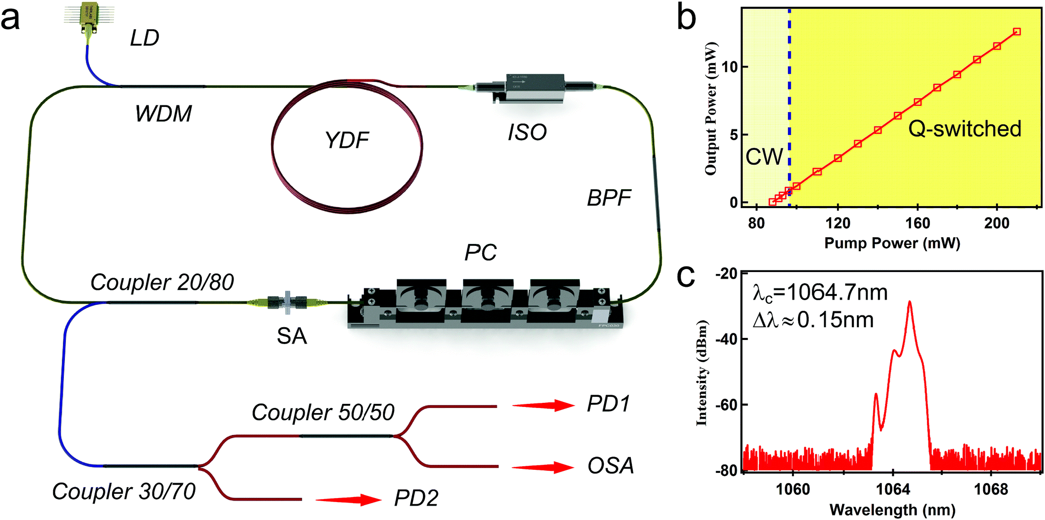 | ||
| Fig. 3 (a) Experimental setup for the Yb-doped all-fiber ring laser based on BP-SA. LD: laser diode; WDM: wavelength division multiplexing; YDF: Yb-doped fiber; PI-ISO: polarization-insensitive isolator; BPF: band-pass filter; PC: polarization controller; OSA: optical spectrum analyser; and PD: photodetector. (b) Relation between output power and input power and (c) spectrum of the laser. | ||
Based on the above experimental setup, the stable Q-switched laser pulse could be achieved when the pump power increased to 96 mW. As is shown in Fig. 3(b), the output power increased linearly with an increase in pump power. The maximum output power was 12.6 mW at the pump power of 210 mW. When the pump power increased above 210 mW, the pulse operation could not be achieved, corresponding to the continuous wave output. However, when the pump power decreased to below 210 mW, the Q-switched pulse could be observed again, which indicated that the BP-SA was not destroyed at a high pump power. The slope efficiency and optical-to-optical conversion efficiency of the laser cavity were about 11.1% and 6%, respectively. As mentioned above, the SA was adsorbed on a fiber ferrule adapter to insert the cavity, which may bring additional optical loss into the cavity. Also, at the output, two additional couplers were connected, which can also bring additional insertion loss. The conversion efficiency can be enhanced if tapered fiber coated with BP-SA is employed or the cavity elements are optimized further.
The pump power was set to 150 mW to observe the pulse characteristics. Fig. 3(c) shows the spectrum of the output Q-switched pulse laser, which centers at 1064.7 nm with a 3 dB bandwidth of 0.15 nm. Fig. 4(a) shows the pulse train with a pulse interval of 58.3 μs, corresponding to a repetition rate of 17.2 kHz. The pulse duration is shown in Fig. 4(b). The pulse envelope was fitted with a Gaussian function. The radio frequency spectrum is illustrated in Fig. 4(c). The fundamental frequency is 17.2 kHz with a signal to noise ratio of 35 dB, which indicates that the Q-switched pulse operation is quite stable.
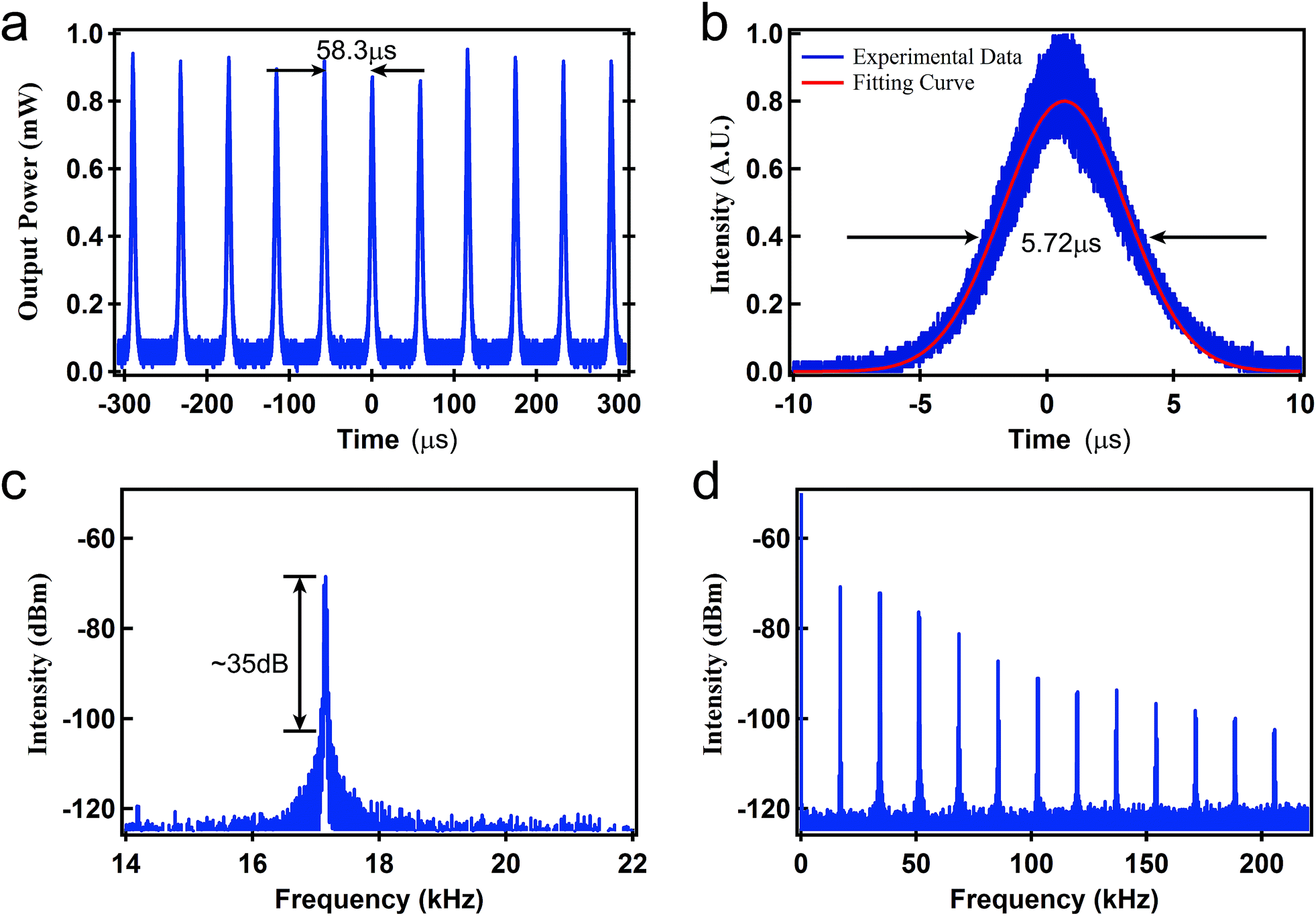 | ||
| Fig. 4 Output laser properties under pump power of 150 mW: (a) pulse train, (b) pulse duration, (c) radio frequency spectrum, and (d) radio frequency spectrum in the frequency range of 200 kHz. | ||
The oscilloscopic traces at different pump power are shown in Fig. 3(a). With an increase in the pump power, the pulse interval decreased, and the pulse repetition rate increased. Fig. 4(b) depicts the repetition rate and pulse duration of the output laser as a function of pump power. As the pump power increased from 100 mW to 210 mW, the repetition rate increased from 8.9 kHz to 32.3 kHz. Although the pulse duration decreased from 14.18 μs to 4.93 μs, the pulse duration showed a slight increase above the pump power of 180 mW. This may be due to the over-saturation of BP-SA at the high pump power. In this case, the BP-SA could not respond instantaneously, thus resulting in the broadening of the pulse duration. This further led to a decrease in peak power, possibly when the pump power approached the maximum value. The pulse energy versus the pump power is also shown in Fig. 5(c). The maximum pulse energy of 450.14 nJ was achieved, corresponding to a maximum peak power of 90.03 mW.
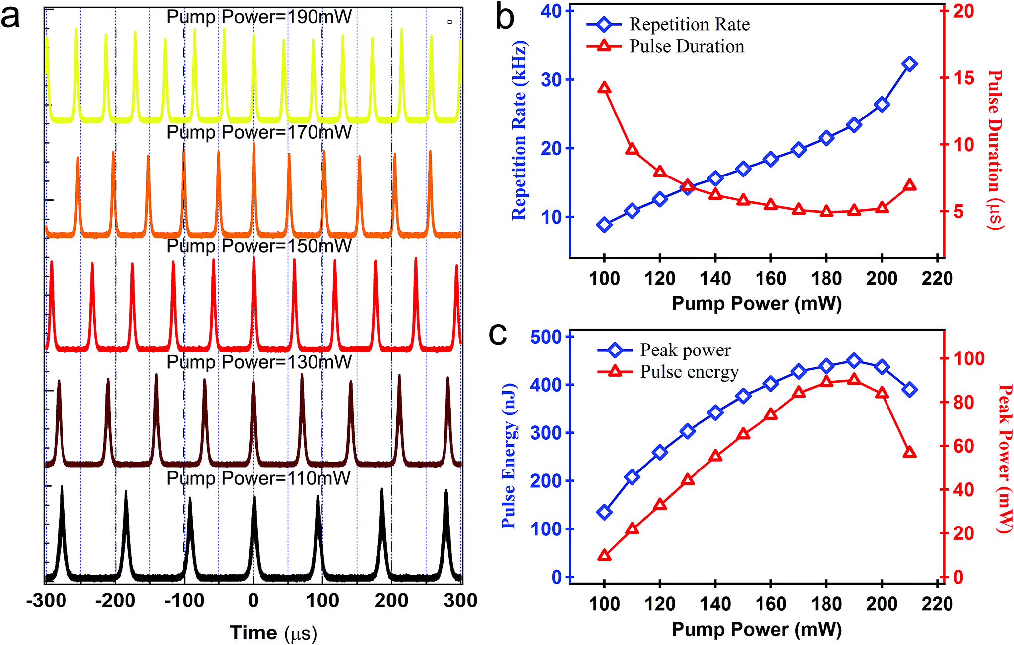 | ||
| Fig. 5 (a) Oscilloscopic traces at different pump powers, (b) repetition rate and pulse duration versus pump power and (c) pulse energy and peak power versus pump power. | ||
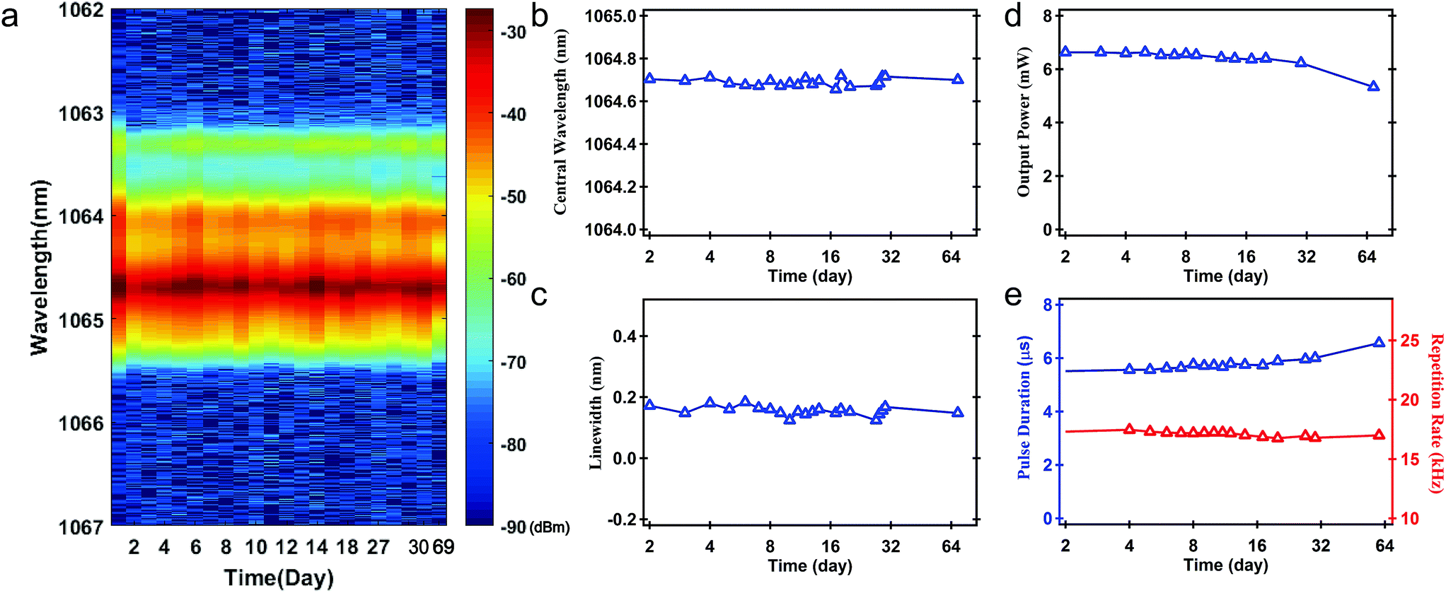
We also tested the stability of the Q-switched pulse. The pulse laser could operate stably for at least 69 days. Fig. 6 shows the typical stability test results under the pump power of 150 mW. From Fig. 6(a)–(c), we can see that the spectrum was quite stable. The central wavelength of 1064.7 nm hardly changed. The fluctuation of output power, repetition rate, and pulse duration from the average values were less than 4.19%, 1.23%, and 3.98%, respectively (Fig. 6(d) and (e)). In the early and late stages of 69 days, we tested the stability of the pulse laser for 4 hours each day. The experimental results indicate that the pulse was also quite stable in single operation (see details in ESI†). According to the structure of BP, the outermost layer of BP has five electrons, so the surface of BP has free charges, making it easy to be oxidized and then degrade in the environment, where water and oxygen coexist. In our work, BP nanoflakes were directly filtered into a thin film after electrochemical exfoliation in a TBA+ solution, exhibiting excellent stability in air. On the one hand, the positive charges of TBA+ can neutralize the negative charges of BP itself, which can improve the stability of the BP nanoflakes. On the other hand, the electrolyte is not volatile and has a relatively high boiling point (242 °C). During the filtration process, a thin layer of residual solvent adhered to the BP surface, behaving as an isolating barrier, which could protect the BP flakes from surface oxidation. Additionally, encapsulating BP-SA in two fiber ferrules weakened the interactions between SA and air or water vapor, which further enhanced its long-term stability. To the best of our knowledge, our pulse laser displays the best stability performance compared with that reported previously.
 | ||
| Fig. 6 Stability results of the pulse laser: (a) emission spectrum, (b) central wavelength, (c) full width at half maximum of the central wavelength, (d) output power, and (e) repetition rate and pulse duration at different time intervals. | ||
In this work, the mode-locked operation was not achieved, which was due to several aspects. First, the cavity loss was too high to achieve the power level for mode-locked operation. The cavity loss was possibly from the cavity elements, fiber ferrule adapter and SA. Besides, the mode-locked operation needs to achieve phase locking among a number of longitudinal modes. However, the 3 dB bandwidth of BPF was less than 0.2 nm in this work, which is too small to achieve mode-locked operation. Furthermore, the thickness of the BP-SA sample could affect the modulation depth, which is a pivotal factor that determines the mode-locked operation. Thus, the mode-locked pulse can be expected by reducing the cavity loss, employing a broadband BPF and improving the BP-SA thickness.
4. Conclusions
In conclusion, a passively Q-switched pulse laser was demonstrated with a BP-SA. Compared to liquid phase exfoliation technology or the mechanical exfoliation method, larger-size and more excellent time stability were achieved in the BP fabricated by a modified electrochemical delamination exfoliation. Based on this BP-SA, the pulse laser can operate stably for at least 69 days. The maximum average output power was 12.6 mW with an 11.1% slope efficiency and 6% optical-to-optical conversion efficiency. The pulse repetition rate could be tuned from 8.9 kHz to 32.3 kHz, while the maximum pulse energy of 450.14 nJ could be achieved, which corresponds to the maximum peak power of 90.03 mW. The experimental results reveal that our BP can be adopted as an ultra-stable SA for application in pulse lasers.Conflicts of interest
There are no conflicts to declare.Acknowledgements
This project was supported by the National Nature Science Foundation of China (Grant No. 61705265), Shenzhen Basic Research Project of Science and Technology (No. JCYJ20170302142433007), the CAS Key Laboratory of Nano-Bio Interface (17GJ02), the Natural Science Foundation of Hunan province (2018JJ3610), and the Open Research Fund of State Key Laboratory of Pulsed Power Laser Technology, the Electronic Engineering Institute (SKL2016KF04).References
- Q. L. Bao, H. Zhang, Y. Wang, Z. H. Ni, Y. L. Yan, Z. X. Shen, K. P. Loh and D. Y. Tang, Adv. Funct. Mater., 2009, 19, 3077–3083 CrossRef CAS.
- T. Hasan, Z. P. Sun, F. Q. Wang, F. Bonaccorso, P. H. Tan, A. G. Rozhin and A. C. Ferrari, Adv. Mater., 2009, 21, 3874–3899 CrossRef CAS.
- W. Liu, L. Pang, H. Han, K. Bi, M. Lei and Z. Wei, Nanoscale, 2017, 9, 5806–5811 RSC.
- S. Zhang, N. Dong, N. McEvoy, M. O'Brien, S. Winters, N. C. Berner, C. Yim, Y. Li, X. Zhang, Z. Chen, L. Zhang, G. S. Duesberg and J. Wang, ACS Nano, 2015, 9, 7142–7150 CrossRef CAS PubMed.
- Z. Luo, Y. Huang, J. Weng, H. Cheng, Z. Lin, B. Xu, Z. Cai and H. Xu, Opt. Express, 2013, 21, 29516–29522 CrossRef PubMed.
- Y. Meng, G. Semaan, M. Salhi, A. Niang, K. Guesmi, Z. Luo and F. Sanchez, Opt. Express, 2015, 23, 23053–23058 CrossRef CAS PubMed.
- Z. Luo, M. Liu, H. Liu, X. Zheng, A. Luo, C. Zhao, H. Zhang, S. Wen and W. Xu, Opt. Lett., 2013, 38, 5212–5215 CrossRef PubMed.
- Y. Chen, G. Jiang, S. Chen, Z. Guo, X. Yu, C. Zhao, H. Zhang, Q. Bao, S. Wen, D. Tang and D. Fan, Opt. Express, 2015, 23, 12823–12833 CrossRef CAS PubMed.
- Y. Xu, X. Jiang, Y. Ge, Z. Guo, Z. Zeng, Q. Xu, H. Zhang, X. Yu and D. Fan, J. Mater. Chem. C, 2017, 5, 3007–3013 RSC.
- H. O. Churchill and P. Jarillo-Herrero, Nat. Nanotechnol., 2014, 9, 330–331 CrossRef CAS PubMed.
- A. N. Rudenko and M. I. Katsnelson, Phys. Rev. B, 2014, 89, 201408 CrossRef.
- V. Tran, R. Soklaski, Y. Liang and L. Yang, Phys. Rev. B, 2014, 89, 235319 CrossRef.
- K. Wu, B. Chen, X. Zhang, S. Zhang, C. Guo, C. Li, P. Xiao, J. Wang, L. Zhou, W. Zou and J. Chen, Opt. Commun., 2018, 406, 214–229 CrossRef CAS.
- F. Zhang, Z. Wu, Z. Wang, D. Wang, S. Wang and X. Xu, RSC Adv., 2016, 6, 20027–20033 RSC.
- Z. Luo, M. Liu, Z. Guo, X. Jiang, A. Luo, C. Zhao, X. Yu, W. Xu and H. Zhang, Opt. Express, 2015, 23, 20030–20039 CrossRef CAS PubMed.
- M. B. Hisyam, M. F. M. Rusdi, A. A. Latiff and S. W. Harun, IEEE J. Sel. Top. Quantum Electron., 2017, 23, 39–43 Search PubMed.
- H. Ahmad, M. A. M. Salim, K. Thambiratnam, S. F. Norizan and S. W. Harun, Laser Phys. Lett., 2016, 13, 095103 CrossRef.
- F. A. A. Rashid, S. R. Azzuhri, M. A. M. Salim, R. A. Shaharuddin, M. A. Ismail, M. F. Ismail, M. Z. A. Razak and H. Ahmad, Laser Phys. Lett., 2016, 13, 085102 CrossRef.
- V. Eswaraiah, Q. Zeng, Y. Long and Z. Liu, Small, 2016, 12, 3480–3502 CrossRef CAS PubMed.
- J. Sotor, G. Sobon, W. Macherzynski, P. Paletko and K. M. Abramski, Appl. Phys. Lett., 2015, 107, 051108 CrossRef.
- K. X. Huang, B. L. Lu, D. Li, X. Y. Qi, H. W. Chen, N. Wang, Z. R. Wen and J. T. Bai, Appl. Opt., 2017, 56, 6427–6431 CrossRef CAS PubMed.
- E. I. Ismail, N. A. Kadir, A. A. Latiff, H. Ahmad and S. W. Harun, RSC Adv., 2016, 6, 72692–72697 RSC.
- Y. Ge, S. Chen, Y. Xu, Z. He, Z. Liang, Y. Chen, Y. Song, D. Fan, K. Zhang and H. Zhang, J. Mater. Chem. C, 2017, 5, 6129–6135 RSC.
- J. O. Island, G. A. Steele, H. S. J. v. d. Zant and A. Castellanos-Gomez, 2D Materials, 2015, 2, 011002 CrossRef.
- S. Yang, K. Zhang, A. G. Ricciardulli, P. Zhang, Z. Liao, M. R. Lohe, E. Zschech, P. W. M. Blom, W. Pisula and K. Müllen, Angew. Chem., 2018, 130, 4767–4771 CrossRef.
- X. Yijun, Y. Jian, F. Linfeng, W. Xinliang, B. Qiaoliang, W. Yu, Z. Kai and Z. Yuegang, Small, 2016, 12, 5000–5007 CrossRef PubMed.
- Z. Guo, H. Zhang, S. Lu, Z. Wang, S. Tang, J. Shao, Z. Sun, H. Xie, H. Wang and X. Yu, Adv. Funct. Mater., 2016, 25, 6996–7002 CrossRef.
- M. Sheik-Bahae, A. A. Said, T.-H. Wei, D. J. Hagan and E. W. Van Stryland, IEEE J. Quantum Electron., 1990, 26, 760–769 CrossRef CAS.
- J. Cheng, J. Hao, H. Liu, J. Li, J. Li, X. Zhu, X. Lin, K. Wang and T. He, ACS Nano, 2018, 12, 5341–5350 CrossRef CAS PubMed.
Footnotes |
| † Electronic supplementary information (ESI) available. See DOI: 10.1039/c8na00221e |
| ‡ Authors contributed equally. |
| This journal is © The Royal Society of Chemistry 2019 |