
 Open Access Article
 This Open Access Article is licensed under a Creative Commons Attribution-Non Commercial 3.0 Unported Licence
Microfluidics and catalyst particles
M.
Solsona†
 *a,
J. C.
Vollenbroek†
a,
C. B. M.
Tregouet†
a,
A.-E.
Nieuwelink
b,
W.
Olthuis
a,
A.
van den Berg
a,
B. M.
Weckhuysen
b and
M.
Odijk
a
*a,
J. C.
Vollenbroek†
a,
C. B. M.
Tregouet†
a,
A.-E.
Nieuwelink
b,
W.
Olthuis
a,
A.
van den Berg
a,
B. M.
Weckhuysen
b and
M.
Odijk
a
aBIOS Lab on a Chip Group, MESA+ Institute for Nanotechnology, University of Twente, Drienerlolaan 5, Enschede, The Netherlands. E-mail: miguel.solsona.alarcon@gmail.com
bInorganic Chemistry and Catalysis, Debye Institute for Nanomaterials Science, Utrecht University, Universiteitsweg 99, 3584 CG Utrecht, The Netherlands
First published on 13th September 2019
Abstract
In this review article, we discuss the latest advances and future perspectives of microfluidics for micro/nanoscale catalyst particle synthesis and analysis. In the first section, we present an overview of the different methods to synthesize catalysts making use of microfluidics and in the second section, we critically review catalyst particle characterization using microfluidics. The strengths and challenges of these approaches are highlighted with various showcases selected from the recent literature. In the third section, we give our opinion on the future perspectives of the combination of catalytic nanostructures and microfluidics. We anticipate that in the synthesis and analysis of individual catalyst particles, generation of higher throughput and better understanding of transport inside individual porous catalyst particles are some of the most important benefits of microfluidics for catalyst research.
1 Introduction
Catalysts are used in many different applications, such as fuel cells, exhaust gas catalytic conversion, water purification and chemical production amongst others. In all these fields, the physical and chemical properties of the nanostructure of solid catalysts are of great importance. Over 80% of chemicals require a solid catalyst during their production, thus the role of nanocatalysts has become crucial in order to achieve a more sustainable society.1 The activity of these solid catalysts relies on their size, shape and accessibility of active sites. Therefore, more monodisperse and uniform catalyst materials can tremendously increase their efficiency.During the past two decades, microfluidics has been widely used to analyse and sort micro- and nanostructures, such as cells and microparticles,2,3 as well as to produce catalyst nanoparticles (NPs) with better control of their morphology and size.4–7 Small volumes, high operation speeds, and small length scales in microfluidic devices give more accurate control of the synthesis parameters affecting the overall quality of the catalyst materials prepared. Although microfluidics is a powerful tool for chemical analysis,8 its use in catalyst characterization is far from reaching its full potential. As previously done in the cell-biology field,9 microfluidics could be an essential tool to characterize single catalyst particles at high throughput. Some critical reviews have focused on the synthesis of nanostructures using microfluidics, either as a general approach5,6 or focused on the microfluidic principle used.7
In this review, we first focus on the latest advances of the microfluidic synthesis of metal and metal oxide nanocatalysts. Second, we show how microfluidics has been used for in situ characterization of nanocatalyst particles in terms of shape, size, activity, selectivity, and composition. Several characterization techniques working in synergy with microfluidics are discussed. After both sections we introduce the possible future applications that microfluidics can open to the heterogeneous-catalysis field. This review is intended to show an overview on synthesis and characterization, while we will highlight future opportunities enabled by the combination of both fields.
2 Synthesis
This section focuses on the most recent approaches within the last 8 years. For a more extensive overview of the synthesis of nanostructures focused on the processes taking place inside the microfluidic systems,5 the final application4 or the microfluidic technology used6,7 we refer the reader to other review articles.2.1 Metal nanoparticles
Metal nanoparticles exhibit very interesting catalytic, optical, chemical, electromagnetic and magnetic properties, all of them depending to a large degree on their size and composition. Regarding catalysis, a decrease of the NP size leads to a surface-area increase per mass, providing more active sites. Also, the surface structure is of vital importance for the NP selectivity: the presence of steps, edges or terraces in the atomic surface can influence the reaction pathways to favour the production of certain compounds over other products.10,11 Therefore, colloidal synthesis procedures to prepare catalytic NPs gained increasing interest over the last few years.12 Usually, catalytic NPs are deposited on catalyst supports in order to stabilize them and avoid NPs clustering. These catalyst supports are porous microstructures made of an oxide and their morphology is of great importance regarding catalytic performance.13Normally, the NPs and catalyst supports are produced in batch reactors with lack of controllability. Microfluidic NP synthesis uses the same reactants as batch procedures, however, with better control of the time and spatial distribution resulting in better size homogeneity.14–17 Also, due to the smaller dimensions, heat transfer, which is dominated by conduction and convection, can be achieved in a faster manner.18–21 Nevertheless, this comes at a price of low throughput and the development of more complex systems. Tables 1–3 show a summary of the structures, techniques, NP size, temperature and reactants used to synthesize metal nanostructures, silica and zeolites using microfluidics. As can be seen, synthesis of metal NPs starts with a metal containing salt solution and a reducing agent, although sometimes the reducing agent is not needed.22,23 Thereafter, usually ligands or surfactants, the so-called capping agents, are used to control the shape and size of the structures. The type and mode of mixing of these ligands have a great influence on the final shape and composition of the NPs.24 The time and contact between reagents are of great importance, both of them being better controlled by microfluidic systems. As stated in previous reviews,5,25 microfluidic synthesis uses two different techniques to bring the reagents into contact, the homogeneous and the droplet-based approaches.
| Material | Microreactor | Size | Temp. | Flow rate | Reactants | Ref. |
|---|---|---|---|---|---|---|
| Au NPs | Glass | 11.5 nm | NS | 0.05 mL min−1 | HAuCl4 + SC + tannic acid | 28 |
| Au NPs | Silicon-glass | 1 nm | NS | 43.3 mL min−1 | HAuCl4 + NaBH4 + PVP | 48 |
| Au NPs | Glass capillary | 48–135 nm | RT | 1 mL min−1 | HAuCl4 + AA + PVP | 49 |
| Au NRs | PTFE | ≈50 nm | NS | 0.1 mL min−1 | HAuCl4 + CTABr + tannic acid + AgNO3 + AA + NaBH4 + PEG | 50 |
| Au NPs | PDMS | ≈40 nm | NS | 0.005–0.07 mL min−1 | Seeds + HAuCl4 + AA | 51 |
| Au NPs | Stainless steel | 24–36 nm | NS | 0.041–3.63 mL min−1 | HAuCl4 | 22 |
| Au hollow NPs | PTFE | ≈40 nm | RT | 0.42 mL min−1 | HAuCl4 + NaBH4 + PVP | 52 |
| Au NPs | PDMS | ≈125 nm | 22–50 °C | NS | HAuCl4 + PDMS curing agent | 23 |
| Au NPs | PE | 2–37 nm | RT | 50 mL min−1 | HAuCl4 + SC + NaBH4 | 30 |
| Au NPs | PTP | NS | NS | 1.7 mL min−1 | HAuCl4 + DMSA + NaBH4 | 53 |
| Au NPs | Teflon and PDMS | 3–25 nm | RT | 10 mL min−1 | HAuCl4 + AA + NaOH | 31 |
| Au NPs | PTE | 4.3–8.7 nm | 25–60 °C | 0.042 mL min−1 | HAuCl4 + dodecanethiol + ET3SiH + THF | 54 |
| Au NPs | PTE | ≈100 nm | NS | 5 × 10⁻⁵ mL min−1 | HAuCl4 + H2SO4 | 38 |
| Au NPs | 3D-printed | ≈10 nm | NS | NS | HAuCl4 + NaBH4 + SC | 47 |
| Au NPs | PEEK | 1–2 nm | 100 °C | 0.08 mL min−1 | HAuCl4 + SC | 14 |
| Au NPs | Glass capillary | 1.8 nm | 100 °C | 0.01 mL min−1 | HAuCl4 + SC | 15 |
| Au NPs | Stainless steel or Teflon | 1.5–181 nm | RT | 0.2–20 mL min−1 | HAuCl4 + AA or NaBH4 | 55 |
| Au NPs | Teflon | ≈40 nm | RT | ≈5.8–7 mL min−1 | HAuCl4 + NaOH + glucose | 40 |
| Au NPs | Silicon-glass | ≈40 nm | RT | NS | HAuCl4 + SC | 56 |
| Au NPs | PVDF | 50 mL min−1 | HAuCl4 + NaBH4 | 57 | ||
| Au NPs | Low temp. ceramic | 3 nm | ≈0.06 mL min−1 | HAuCl4 + NaBH4 + MUA | 58 | |
| Au NRs | Rotating tube | ≈30 nm | RT | 10–40 mL min−1 | HAuCl4 + acetylacetone + CTAB + AgNO3 + carbonate buffer | 59 |
| Ag NPs | PDMS | 5–12 nm | RT | 20 mL min−1 | AgNO3 + NaBH4 + AA + PVP | 34 |
| Ag NPs & fibres | PDMS | 30 nm | RT | 0.015–0.06 mL min−1 | AgNO3 + OPD | 27 |
| Ag NPs | Glass capillary | 3.1–9.3 nm | RT | 2.5 mL min−1 | AgNO3 + SC + NaBH4 | 36 |
| Ag NPs | Quartz spiral | 5–40 nm | 130–150 °C | 1 mL min−1 | Ag(NH3)2 + glucose + PVP | 60 |
| Ag NPs | ETFE and PTFE | 5.3–7 nm | 90 °C | 0.2–0.6 mL min−1 | AgNO3 + NaOH + C. Platycladi | 61 |
| Pd NPs | Silicon-glass | 1 nm | 60 & 280 °C | 1 mL min−1 | Pd acetate + toluene + methanol + OLA + TOP | 62 |
| FeZn NPs | Stainless steel | ≈5 nm | 30 & 150 °C | 3 mL min−1 | FeCl2 + ZnCl2 + NaBH4 + PVP | 63 |
| Fe3O4 NPs | PTFE | ≈11 nm | 60 °C | 2.5–5 mL min−1 | FeCl2 + FeCl3 + NaBH4 + PVP | 16 |
| Fe3O4 NPs | Hastelloy | 4.9 nm | 250 °C | 0.19–6.6 mL min−1 | Fe(acac)3 + anisole + (HOOC–PEG–COOH) + oleylamine | 29 |
| Cu NPs | Stainless-steel | ≈10 nm | RT | 0.1–40 mL min−1 | CuSO4 + NaBH4 + PVP | 33, 34 |
| Cu NPs | Teflon | 135.6 nm | RT | 1.8 mL min−1 | CuCl2 + THF + LiBEt3H + SB12 + acetone + ethanol | 64 |
| CoFe2O4 NPs | PDMS and PTFE | 5–15 nm | 98 °C | NS | CoCl2 + FeCl3 + TMAOH | 37 |
| Ni NPs | 10 nm | 220 °C | 2.2 mL min−1 | Ni(acac)2 + oleylamine + octadecene + trioctylphosphine | 17 | |
| Ni NPs | Stainless steel | 5–9 nm | 80 °C | 0.1–40 mL min−1 | NiSO4 + N2HH4 + PVP + NaOH | 65 |
| Ni NPs | Stainless-steel | 5.3–7.4 nm | 60–120 °C | 3 mL min−1 | NiCl2 + hydrazine monohydrate + NaOH + EG | 66 |
| Pt NPs | PTFE | 2.8 nm | RT | 0.02–0.5 mL min−1 | H2PtCl6 + PVP + HMP + UV (365 nm) | 39 |
| Pt NPs | Copper | 5 nm | RT | 0.84–1.7 mL min−1 | K2PtCl6 + NaBH4 + PVP | 67 |
| Pt NPs | Glass | 1.4 nm | 0 °C | 6.7 mL min−1 | H2PtCl6NaBH4 + PVP | 68 |
| Material | Microreactor | Size | Temp. | Flow rate | Reactants | Continuous phase | Ref. |
|---|---|---|---|---|---|---|---|
| Au NSs | PDMS | 20–50 nm | NS | 0.0025 mL min−1 | Seeds + HCl + AA + AgNO3 + PVP + DMF | HFE-7500 + 2.5% Picosurf-1 | 69 |
| Au NPs | PDMS | ≈4 nm | RT | 0.0083 mL min−1 | HAuCl4 + BMIM-Tf2N + methylimidazole + BMIM-BH4 | Fluorocarbon oil | 70 |
| Au NPs | PDMS | ≈4 nm | RT | 0.0083–0.015 mL min−1 | HAuCl4 + methylimidazole + BMIM-BF4 | Polychlorotrifluoro-ethylene oil | 71 |
| Cu NPs | PDMS | ≈10 nm | RT | 0.17–0.51 mL min−1 | CuSO4 + NaBH4 + PVP + NH3 + NaOH | 72 | |
| Ag NCs | PTFE and glass capillary | 30–100 nm | 150 °C | 0.1–0.3 mL min−1 | (Ag seeds) + AgNO3 + PVP + EG | Air or silicone oil | 73 |
| Au NPs | PTFE and PEEK | 2.5–4 nm | RT | 0.087–0.7 mL min−1 | HAuCl4 + photoinitiator + AA + PVP | PP9 | 74 |
| Pd NPs | PTFE and glass capillary | 8.1–9.1 nm | 80 °C | 0.01–0.06 mL min−1 | Na2PdCl4 + PVP + AA + KBr | Silicon oil | 75 |
| Fe3O4 NPs | PTFE, silicon tubing and glass capillary | 3.6 nm | NS | 0.067–0.6 mL min−1 | FeCl2 + FeCl3 + dextran + NH3OH | Octadecene | 76 |
| FeMn NPs | PDMS | ≈3.6 nm | NS | 0.0015 mL min−1 | FeSO4 + MnCl2 + E. coli + PEG-PFPE | G-Oil and Abil-EM90 | 77 |
| Pd NPs | PTFE and glass capillary | 9–37 nm | 80 °C | 80 mL min−1 | Na2PdCl4 + PVP + AA + KBr | Silicon oil | 78 |
| Pt NPs | PTFE | 15 nm | RT | 0.175 mL min−1 | H2PtCl6 + PVP + HMP + UV (365 nm) | PP9 | 79 |
| Ag NPs | PEEK and PMMA | 5–20 nm | NS | 0.035–1 mL min−1 | AgNO3 + KOH | Air or kerosene | 80 |
| Au NPs | Silicon-glass | ≈3–8 nm | 100 °C | 0.027–300 mL min−1 | HAuCl4 + NaBH4 | Air, silicon oil or toluene (droplets) | 81 |
| Material | Microreactor | Size | Temp. | Flow rate | Reactants | Ref. |
|---|---|---|---|---|---|---|
| CoFe2O4 NPs | PDMS and PTFE | NS | 98 °C | NS | CoCl2 + FeCl3 + TMAOH | 37 |
| AuPd NPs | PTFE and PEEK | 10 nm | NS | 80 mL min−1 | Pd seeds + KBr + PVP + AA + HAuCl4 | 78 |
| AuPd NPs | Zirconia | 0.9–2.8 nm | NS | 43.3 mL min−1 | HAuCl4 + H2PdCl4 + NaBH4 + PVP | 35 |
| PtBi NPs | Capillary | 260 & 350 °C | NS | BiNO3 + H2PtCl6 + NaBH4 + PVP + EG + PG | 82 | |
| FePt NPs | Stainless steel | ≈2 nm | 120 °C | 0.8–1.5 mL min−1 | FeCl2 + H2PtCl6 + SnCl2 + PVP + NaBH4 | 83 |
| Ag/CuO2 core–shell NPs | PTFE | ≈100 nm | 0.25–0.5 mL min−1 | (Ag seeds) + CuSO4 + NaOH + AA | 84 | |
| CdSe NPs | 5 nm | 250 °C | 0.42 mL min−1 | CdO + Se + TOP + E acid | 85 | |
| CdSe NPs | PMMA | 4 nm | 250 °C | 0.05 mL min−1 | CdO + Se + TOP + oleic acid | 86 |
| CdSe NPs | Capillary | 3–10 nm | 250 °C | 0.05–0.6 mL min−1 | Cd(OAc)2 + Se + TOP + oleic acid | 87 |
| CdSe NPs | PTFE reactor | ≈3 nm | 300 °C | 0.6 mL min−1 | CdO + Se + TOP + oleic acid | 88 |
| PbS NPs | PTFE and PEEK | ≈5 nm | 80–150 °C | 0.03–0.06 mL min−1 | Pb(OAc)2 + TMS2S + Se | 89 |
| SiO2 | PDMS | 8 μm, 3 nm pores | RT | TEOS + CTAB + HCl + ABIL EM 90 | 90 | |
| SiO2 | PDMS | 10–30 μm | NS | 1 × 10⁻³ mL min−1 | TEOS + P123 + HNO3 | 91 |
| SiO2 | PDMS | 800 nm hollow | RT | 0.4 mL min−1 | TEOS + NH4OH + CTAB | 92 |
| SiO2 | PDMS | 34 μm | RT | 16.5 × 10⁻³ mL min−1 | TEOS + P104 + ethanol + HCl | 93 |
| Zeolite A | Stainless steel and PTFE | 0.9–1.5 μm | 90 °C | 0.2–1 mL min−1 | NaOH + SA + SC | 94 |
| Zeolite A | Stainless steel and PTFE | ≈400 nm | 90 °C | 0.2–0.85 mL min−1 | NaOH + SA + SC | 95 |
| Zeolite A | Stainless steel and PTFE | 70–1500 nm | 80–100 °C | 0.13 mL min−1 | NaOH + SA + SC | 96 |
| Zeolite A | PFPE and PFA | ≈100 nm | 100 °C | 2 × 10⁻³–5 × 10⁻³ mL min−1 | NaOH + TMAOH + TEOS | 97 |
| HKUST-1 | PDMS and PFA | 1–15 μm | 90–140 °C | 10−3–0.012 mL min−1 | Cu(NO3)2·H2O + H3BTC + EtOH + DMF | 98 |
| MOF-5 | Zn(NO3)2·6H2O + H2BDC + DMF | |||||
| IRMOF-3 | Zn(NO3)2·6H2O + H2BDC–NH2 + DMF | |||||
| UiO-66 | ZrCL4 + H2BDC + HCl + DMF | |||||
| HKUST-1 | Digital microfluidics | 5 μm | NS | Cu(NO3)2 + H3BTC + DMSO | 99 |
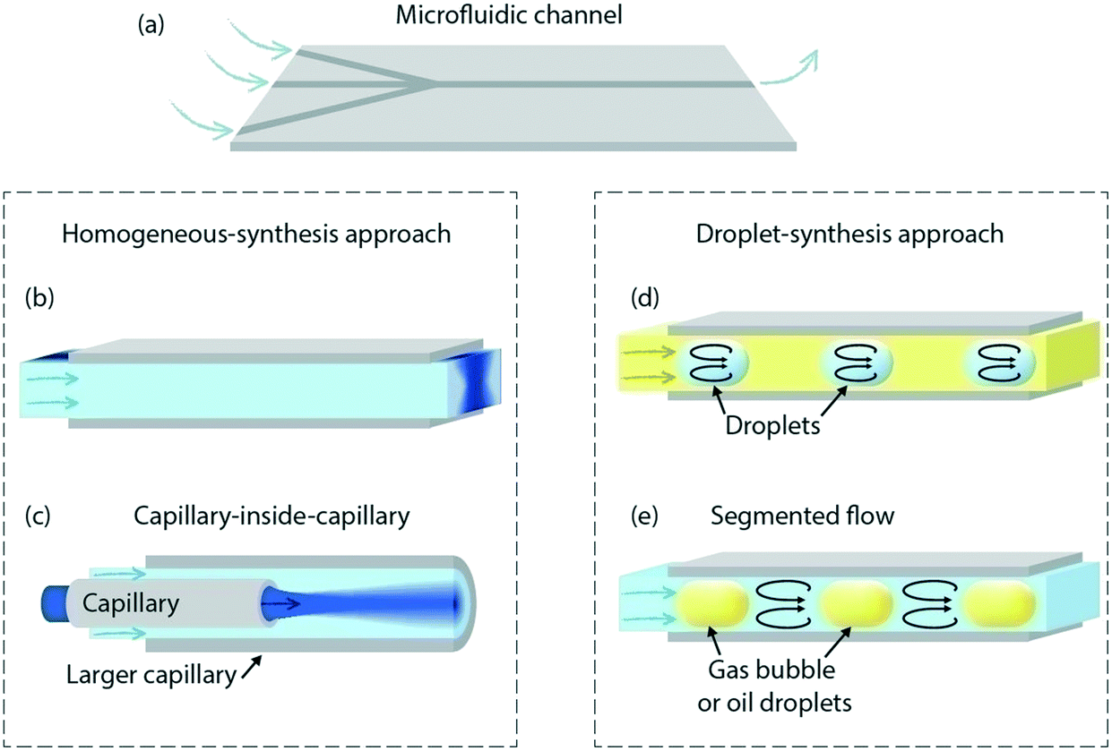 | ||
| Fig. 1 (a) Schematic drawing of a typical microfluidic chip used to synthesise NPs that consists of 3 inlets and 1 main channel. (b) Main channel section where the 3 different inlets merge into a single channel. (c) Tube inside tube configuration where the contact of both reagents occurs at the centre of the big channel. (d) Droplets of similar size formed using a typical microfluidic droplet generator and (e) mixing of the segmented flows separated by gas bubbles or oil droplets. | ||
2.2 Bimetallic NP, quantum dot, silica particle, zeolite and MOF synthesis
An overview of the synthesis of other kinds of particles such as: bimetallic NPs, quantum dots (QDs), silica microparticles, zeolites and metal-organic frameworks (MOF) is briefly mentioned but not comprehensively summarized in Table 3.Bimetallic NPs have unique properties due to their synergetic effect on catalytic reactions. By combining two metals or metal oxides the properties of the final NPs can differ from those of the pure metal NPs of the initiators. Bimetallic NP synthesis is performed by mixing both salt solutions, providing a mixed alloy, Fig. 2a, or by controlling the deposition rate of a second metal on a seed from the first one, Fig. 2b. Some studies have shown that NPs synthesised using microfluidic technologies have high electro- or photocatalytic activity.82–84
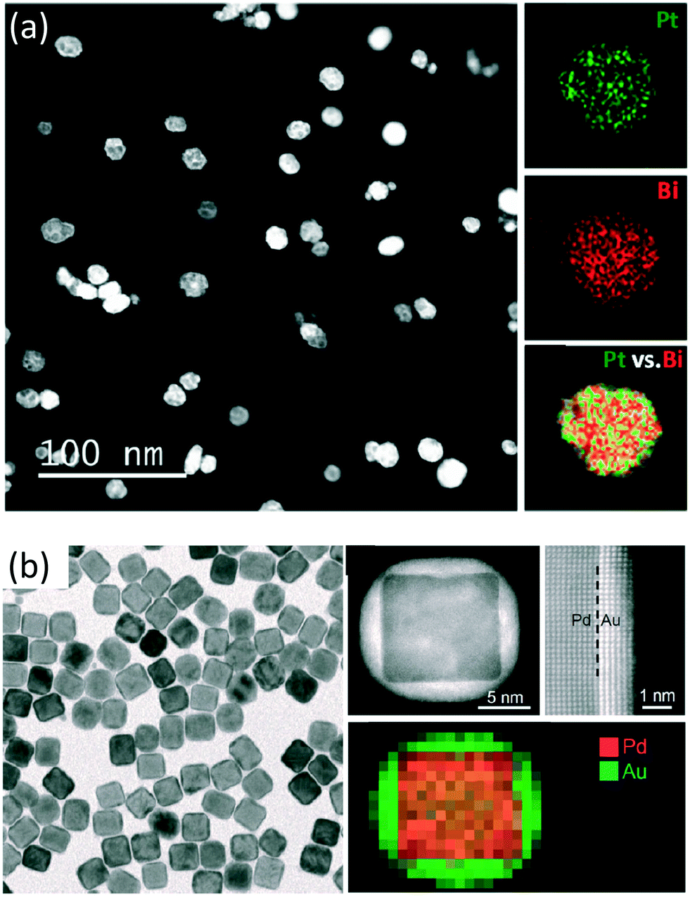 | ||
| Fig. 2 (a) HAADF-STEM image and EDS element maps of PtBi intermetallic NPs. Reprinted (adapted) with permission from Zhang, D. et al.216 Copyright (2015) American Chemical Society. (b) TEM image, HAADF-STEM image and EDX mapping of Pd–Au core–shell nanocrystals obtained using seeded growth of Au on the 18 nm Pd cubes. Reprinted (adapted) with permission from Zhang, L. et al.217 Copyright (2014) American Chemical Society. | ||
QDs are semiconductor particles smaller than 10 nm in diameter and their unique optical properties are very dependent on their size.102 They are normally made of CdSe, CdS, InP or PbS and have been extensively synthesised using microfluidics due to the controllability enabled by this technology. As examples, Wang et al. could control the size and shape of QDs by using a standard microfluidic setup88 and Lignos et al. could study the kinetics of PbS formation in small droplets inside a microfluidic chip.89 QDs such as CdSe are always synthesised at high temperatures which can be very well controlled in microreactors, Table 3. Recently, a 6-step (microfluidic chip) procedure was used to fabricate different types of core–shell QDs in a very controllable and reproducible manner.103
To prevent aggregation of the catalytic NP dispersion inside the channel while driving catalytic reactions, catalyst supports are used to stabilize the NPs.13 These supports are frequently made of silica, alumina or titania and they need to be very stable at high temperatures and pressures. Furthermore, they are often very porous to increase the available surface area. Various studies have synthesised porous silica microparticles,94–97 however, not with a catalytic purpose. Bchellaoui et al. used droplet microfluidics to synthesise very monodisperse porous microparticles.91 This confirms the suitability of this technology to fabricate catalyst supports.
Zeolites are another class of commonly used catalysts, due to their nanoporosity and their acidity. However, very few studies have tried to implement their synthesis in microfluidics. Indeed, depending on the type of zeolite, the synthesis conditions can vary from room temperature to high temperatures (typically 200 °C for the reaction and more for the calcination step104). In zeolite synthesis precise control of the synthesis conditions is important, because there are many different types of zeolites in terms of their structure. A small change in the conditions may change the structure. That is why zeolites have been synthesized at the sub-millimeter range in microfluidic chips in droplets,94,95,97,105 but only syntheses at relatively low temperatures and short reaction times have been investigated so far. The catalytic activity of these microfluidic-synthesized zeolites has been shown to decrease the reaction time of alkyl borate synthesis by a factor of ten.97
Metal organic frameworks (MOFs) are crystalline structures that can be used as heterogeneous catalysts. These materials are normally porous and can contain different transition metals or functional groups which can be very suitable for catalysis.106 Few studies have been found to use microfluidics to synthesize MOFs.107 In this work, the authors synthesised different kinds of MOF structures claiming that the time needed could be decreased from a few hours to a few minutes by using microfluidic technologies.98
2.3 Conclusions
Catalyst NPs have been extensively synthesised using microfluidics. The shape and size of the particles are very dependent on the contact form and time between the different reagents. However, few studies were found where they synthesised bimetallic NPs, zeolites and catalyst supports. It has been demonstrated that microfluidic synthesis of nanostructures provides a more uniform and reproducible approach. However, low throughput seems to be the main drawback hindering the widespread adaption by industry.Progress made in catalyst NP synthesis is realized by fine characterization methods enabling the analysis of the NPs and the quantification of their catalytic activity. Integration of these methods in microfluidic devices to analyse the NPs in situ could lead to fast analysis with few materials for rapid feedback on the synthesis. The next section presents recent advances in NP characterization and supported catalyst materials in microfluidics.
Whilst low throughput has always been the main drawback for industry purposes, it is possible to increase it by producing larger droplets while maintaining good control of the system homogeneity.78 For catalysis, no studies were found synthesizing catalyst NPs on top of catalyst supports all together in the same process. Controlling the NP location on the catalyst supports could increase the catalytic efficiency of the NPs per mass which is of great interest when dealing with noble metal materials. Also, no clear information was found regarding the selection of ligands, which play a crucial role in the synthesis of NPs. In general, if microfluidics can control the synthesis and location of NPs on catalyst supports, thereby increasing the throughput in a cost-effective manner, we foresee great potential for microfluidics in industry.
3 Characterization
3.1 Introduction
In microfluidic synthesis, in situ (direct) characterization can act as a fast feedback mechanism on important synthesis parameters such as the flow rate and temperature. Examples of the additional parameters that determine the success rate of NP synthesis are the size, shape, uniformity, oxidation state, activity and purity. In situ measurements allow for information at different stages in both time and space during synthesis or activity testing of catalyst materials. With this information, the growth rate, reaction intermediates and deactivation can be monitored26,53,57,62,108–112 allowing for kinetic and mechanistic studies,108,113–117 as summarized in Table 4 and illustrated in Fig. 3.| Catalyst support (reactor type) | Measured property | Analytical technique | Temp. | Reactor material | Ref. |
|---|---|---|---|---|---|
| Pt/PMMA–polyDADMAC (packed-bed) | Degradation of cochenille red with sodium borohydride | Optical/VIS: photometer | 25–80 °C | Glass microtube | 79 |
| Pt/SiO2, Au/TiO2, silicon-glass chip and Au/Al2O3 (wall coated) | Bonding state and chemical state of Au/TiO2 (XANES) – coordination numbers and bond lengths for Au/Al2O3 (EXAFS) – crystal structure of TiO2 support in Au/TiO2 (EXAFS) – intermediates and products in ethylene hydrogenation (IR and GC) | XANES, EXAFS, IR and GC | 40–200 °C | Silicon–silicon chip with silicon nitride windows | 108 |
| Pt/ZnO nanorods (wall coated) | Photocatalytic activity measured with the degradation of phenol | UV-vis | NS | Fused-silica capillary | 109 |
| ZnO/TiO2 (wall coated) | Photocatalytic kinetic performance with the degradation of methylene blue | UV-vis | NS | Fused-silica capillary | 110 |
| Rh/Al2O3 (wall-coated) | Oxidation state of Rh during partial oxidation of methane (XANES) – selectivity and conversion for direct partial oxidation of methane (MS) | XANES and MS | 331–378 °C | Quartz capillary | 111 |
| Pt/Al2O3 and Pd/Al2O3 (packed-bed) | Propane formation from propylene and para-hydrogen – density of catalyst sites | NMR | NS | Capillary (not specified) | 112 |
| M–TiO2 (M = F, Si, K, Mn, Co, Ni, Cu, Mo, and Au) (packed-bed) | Photocatalytic activity measured with the degradation of methylene blue | Optical/vis: CCD camera | NS | Glass–glass | 113 |
| TiO2 (wall-coated) | Photocatalytic activity measured with the degradation of Rhodamine B | UV-vis | NS | Fused-silica capillary | 114 |
| Ru nanoparticles (wall-coated in polymeric matrix) | Catalytic activity by hydrogenation of various carbonyl compounds | GC-MS | <160 °C | Fused-silica capillaries | 115 |
| Au/SiO2 (packed-bed) | Cascade dihydropyran synthesis, yield and selectivity (IR and GC) – oxidation state indicating catalyst deactivation (EXAFS) | IR, GC, and EXAFS | NS | Stainless steel plug flow reactor | 116 |
| Au nanoparticles (wall-coated) | Reduction of p-nitrothiophenol – influence of O2 and H2 on dimerization of p-aminothiophenol | SERS | NS | Glass–PDMS | 117 |
| Cu/ZnO (packed bed) | Activity by methanol to hydrogen conversion | GC | 195–260 °C | Silicon-glass chip | 123 |
| Pt–Co/Al2O3 (wall-coated) | Oxidation state of Co and Co oxides (Raman) – CO conversion, O2 conversion and CO2 selectivity for preferential oxidation of carbon monoxide (GC) | Raman and GC | 120–160 °C | Fe–Cr–Al capillary in a stainless steel tube | 124 |
| Pt thin film (catalyst spot 15 μm2) | Catalytic activity by CO oxidation | MS | <300 °C | Silicon-glass | 125 |
| CuxPdyAu(1−x−y) alloy surface (wall-coated) | Catalytic activity by H2–D2 exchange reaction | MS | 27–327 °C | Glass–glass chip | 126 |
| Pd/Al2O3 (packed-bed) | Turn over frequency (TOF) for oxidation of carbon monoxide | FTIR and GC | 250 °C | Silicon-glass | 127 |
| Pt/Al2O3 and Rh/Al2O3 (fixed-bed) | Deactivation by monitoring oxidation state during reaction (XANES) | XANES and MS | 352 °C | Quartz glass capillary | 129 |
| Conversion of partial oxidation of methane (MS) | |||||
| Au–Pd/TiO2 (packed-bed) | Conversion and selectivity for the oxidation of benzyl alcohol | Raman | 80–140 °C | Silicon-glass chip | 130 |
| Rh/SiO2 (packed-bed) | Turn over frequency (TOF) for propene hydrogenation with hyperpolarized hydrogen | NMR | 60 °C | Capillary (not specified) | 131 |
| Pd/carbon and zeolite Y and beta (multiple particles in droplet) | Yield for the acylation of anisole | ATR-IR | 20–150 °C | PFA tubing | 132 |
| PtNi nanoparticles (wall-coated) | Hydrogenation of azobenzene dye | UV-vis | NS | Photonic crystal fiber | 133 |
| Pt film (wall-coated) | Adsorption of CO on Pt film | ATR-IR | NS | Stainless steel tube | 134 |
| Au–Pt–Au NPs (suspension) | Reduction of 4-nitrothiophenol by adsorbed hydrogen | SERS | 5–50 °C | Glass–glass | 135 |
| Au–Ag alloy NPs (wall-coated) | Reduction of 4-nitrophenol for kinetic study of various Au/Ag ratios | UV-vis | NS | Silicon-glass | 136 |
| TiO2 graphene oxide (wall-coated) | Photocatalytic activity measured with the degradation of methylene blue | Optical/vis: absorbance through channel | NS | PDMS–PDMS | 138 |
| Pt/Al2O3 (packed-bed) | Pt dispersion in Pt/Al2O3 catalyst layer | CO chemisorption and GC | 25–250 °C | Silicon-glass chip | 148 |
| Zeolite H-ZSM-5 (packed-bed) | Deposition and dissolution of asphaltenes in H-ZSM-5 | Raman and UV-vis | NS | Silicon-glass chip | 149 |
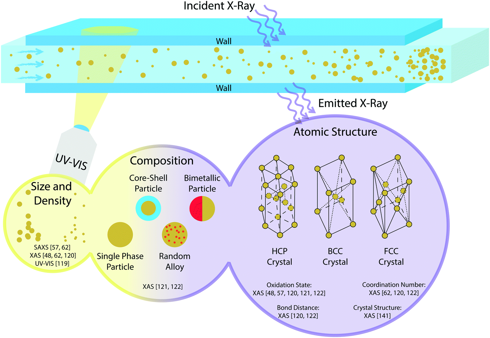 | ||
| Fig. 3 Schematic overview of in situ characterization techniques for catalyst nanoparticle synthesis, as found in the literature, using UV-vis spectroscopy and X-ray absorption spectroscopy (XAS). | ||
To narrow down the scope of this section, only in situ characterization will be discussed, and it is divided into three parts. First, characterization techniques used in microfluidics will be discussed. Second, direct characterization of NPs will be discussed, where the characterization of the shape, size, oxidation state, crystal structure and elemental composition is analysed,26,53,57,62,118–121 as can be found in Fig. 3. Last, the activity of these NPs supported on porous materials forming packed-bed or wall-coated microreactors will be treated. Catalyst NPs are often supported on porous oxides or polymers to provide stability and prevent sintering of NPs. In the characterization of supported catalyst particles, mainly the activity and selectivity of the catalyst material are of interest. Furthermore, the dispersion and stability over time of the catalyst on the support are important.
An overview of the characterization methods found in the literature is shown in Table 4. Here, the type of reactor and the nanoparticle/support combination are listed together with the type of study, characterization and the temperature reported. In the review of Yue et al. 2012,122 the combination of spectroscopy and microreactors was already discussed in great and excellent detail. In their review the working principles of various spectroscopic techniques such as fluorescence spectroscopy (FS), infrared (IR), ultraviolet-visible (UV-vis), Raman spectroscopy (RS), nuclear magnetic resonance (NMR), and X-ray absorption spectroscopy (XAS) are discussed extensively. In contrast, we will briefly discuss the working principles of the aforementioned techniques, and focus on the use of these techniques in in situ catalyst- and nanoparticle characterization.
3.2 Characterization techniques
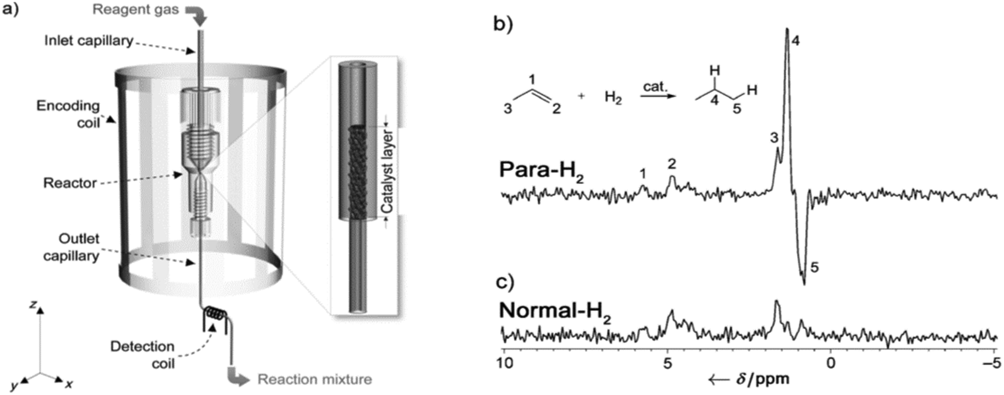 | ||
| Fig. 4 a) Experimental setup. Gaseous mixture containing para-hydrogen and propene flows through the catalyst bed packed inside the inlet capillary close to the connection between the inlet and the outlet capillaries. Three types of capillaries of different diameters (ID 800, 405, and 150 μm) were used as the inlet capillary. The diameter of the outlet capillary was constant in all experiments (ID 150 μm). The catalyst bed was placed inside the encoding coil. b) and c) 1H NMR spectra of the reaction mixture measured using the detection microcoil in the experiments with b) para-hydrogen and c) normal hydrogen at 22 °C. The reaction was carried out in an R-800-5 reactor. Reproduced with permission from Zhivonitko, V. V. et al.218 Copyright Wiley-VCH Verlag GmbH & Co KGaA, Weinheim, 2012. | ||
 | ||
| Fig. 5 a) SEM image of the Kagome HC-PCF used in the experiments, b) TEM image of 6.3 nm PtNi NPs, and c) optical setup used for the DR1 hydrogenation in particle-deposited Kagome HC-PCFs. The left photograph shows the side-view of the irradiated Kagome HC-PCF. The right photograph shows the guided mode in the core, when the fiber is filled with isopropanol and impregnated with 6.3 nm PtNi NPs. M, mirror; MMF, multimode fiber. Reproduced with permission from Ponce, S. et al.219 Copyright Wiley-VCH Verlag GmbH & Co KGaA, Weinheim, 2018. | ||
X-Ray absorption spectroscopy (XAS), in particular extended X-ray absorption at fine structures (EXAFS) and X-ray absorption near edge structures (XANES), is a very powerful technique in characterizing the composition, bond distance, oxidation state, coordination number and crystal structure of nanoparticles,26,53,57,62,108,119–121,140 as shown in Fig. 3. Disadvantages of XAS measurements are the need for an extensive database of reference samples and the time-consuming and complex data analysis that is needed to extract the desired information. Still, it can be noticed that microfluidics is much used, and actually required in XAS measurements due to the requirement of small volumes and reactor dimensions in synchrotron facilities. As an example, the microreactor used by Gross et al. 2014 (ref. 116) benefits from the micrometre-range channel heights, as less X-ray intensity is lost in XAS transmission mode. Furthermore, the spatial resolution of 15 μm that can be achieved with synchrotron measurements can be used to measure along multiple points in the microfluidic channels. For UV-vis it is not strictly necessary to use small volumes and reactors, although it is still an advantageous technique to combine with microfluidics,73,109,110,114,133,136 as summarized in Table 4. Furthermore, UV-vis is a much more accessible technique, since no synchrotron facilities are required to perform measurements.
Besides monitoring the formation and growth of nanoparticles, XAS can also be used to monitor the state of catalysts during operation. Change in the chemical state, crystal structure and oxidation state gives information about the performance of the catalyst in terms of deactivation and the mechanism of the reaction,108,111,116,129 as summarized in Table 4. This information is of importance because deactivation is a common phenomenon in catalysis.141 More about catalyst deactivation will be discussed later in section 3.3. Fig. 6 shows an example of a typical XAS setup.111 With this setup they monitored the oxidation state of a Rh/Al2O3 catalyst during the catalytic partial oxidation of methane. Fig. 7 shows the different oxidation states of the catalyst along the catalyst bed.
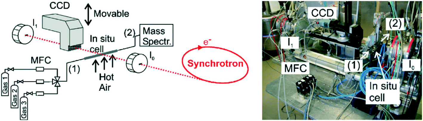 | ||
| Fig. 6 Schematic setup and picture for mapping the oxidation state inside a catalytic reactor in two dimensions under reaction conditions; CCD-detector (position-sensitive detection of the X-ray absorption) and ionization chambers (“integral” X-ray absorption spectra) as well as the microreactor (in situ cell), oven and gas supply including MFCs (mass flow controllers) are depicted; (1) denotes the inlet of the in situ cell and (2) the outlet connected to a mass spectrometer (taken from ref. 111). Reprinted from Hannemann, S. et al.221 Copyright (2007) with permission from Elsevier. | ||
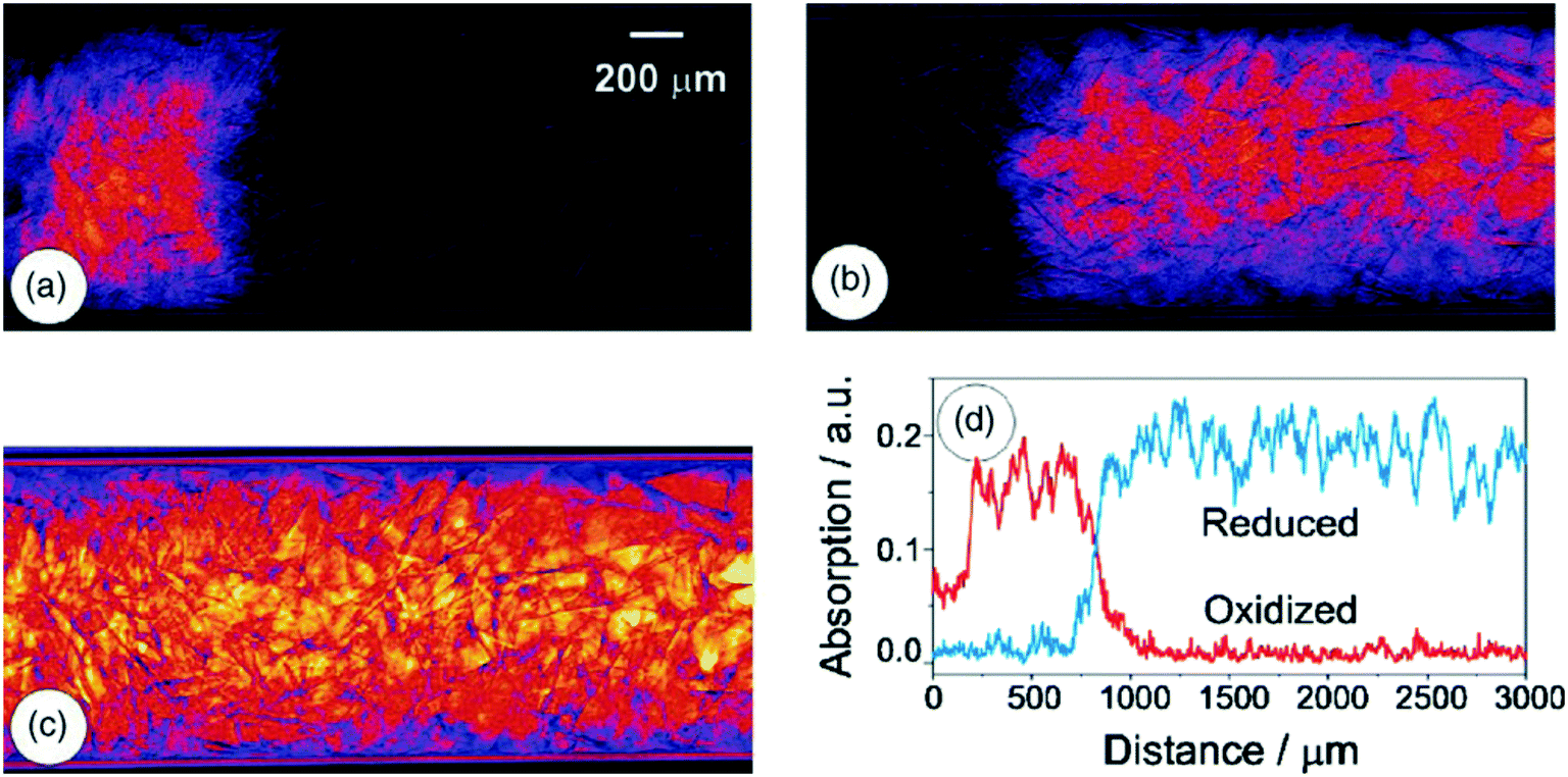 | ||
| Fig. 7 Extracted components from the analysis of the 160 dark- and flat-field corrected transmission images: (a) oxidized Rh-species, (b) reduced Rh-species, (c) featureless background, and (d) relative concentration of the oxidized (red) and reduced (blue) Rh-particles in the axis of the fixed-bed (conditions: 362 °C, space velocity 1.9 × 10⁵ h−1). Reprinted from Hannemann, S. et al.220 Copyright (2007) with permission from Elsevier. | ||
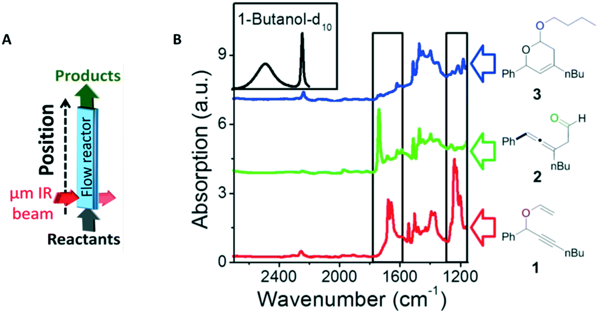 | ||
| Fig. 8 (A) A scheme of the micro-IR flow reactor and (B) the FTIR spectra of the reactant, vinyl ether 1 (red), the primary product, allenic aldehyde 2 (green), and the secondary product, acetal 3 (blue). High-energy regime of IR absorption spectra of butanol-d10 (black), the second reactant, is shown as well. The black rectangles mark the areas in which the IR spectra of the different reactants and products can be easily distinguished from each other. Reprinted (adapted) with permission from Gross, E. et al.221 Copyright (2014) American Chemical Society. | ||
A disadvantage of using IR is the poor signal-to-noise ratio when water is used. Water itself has very broad and strong IR absorption and will likely dominate the spectrum.
A technique that allows working with water is Raman spectroscopy. Similar to IR spectroscopy, it is a vibrational spectroscopic technique. Raman spectroscopy monitors the inelastic scattering of light when interacting with a sample molecule.122 Furthermore, Raman- and IR spectroscopy are based on different selection principles, namely polarizability and dipole moment change. This leads to both techniques being complementary to each other: vibrations that are not shown in the IR spectrum are visible in the Raman spectrum and vice versa.143–145 However, Raman spectroscopy comes with its own disadvantages: spontaneous inelastic scattering typically only happens once every 106 photons. This makes RS signals very weak, although there are ways to enhance the signal e.g. by using surface enhancement structures.117,146,147 As an example, the catalytic reduction of p-nitrothiophenol (PNTP) on gold NPs was performed and measured using surface enhanced Raman spectroscopy (SERS).117 Surface enhancement takes place when compounds are in very close proximity to nanoparticles that show plasmonic resonance. In the local surface plasmon resonance field, the Raman scattering is enhanced.135Fig. 9A shows the reactor used in the catalytic reduction of PNTP, and the corresponding SERS spectra obtained are shown in Fig. 9B. With SERS the authors were able to calculate the rate constant for the PNTP reduction, see Fig. 9C.
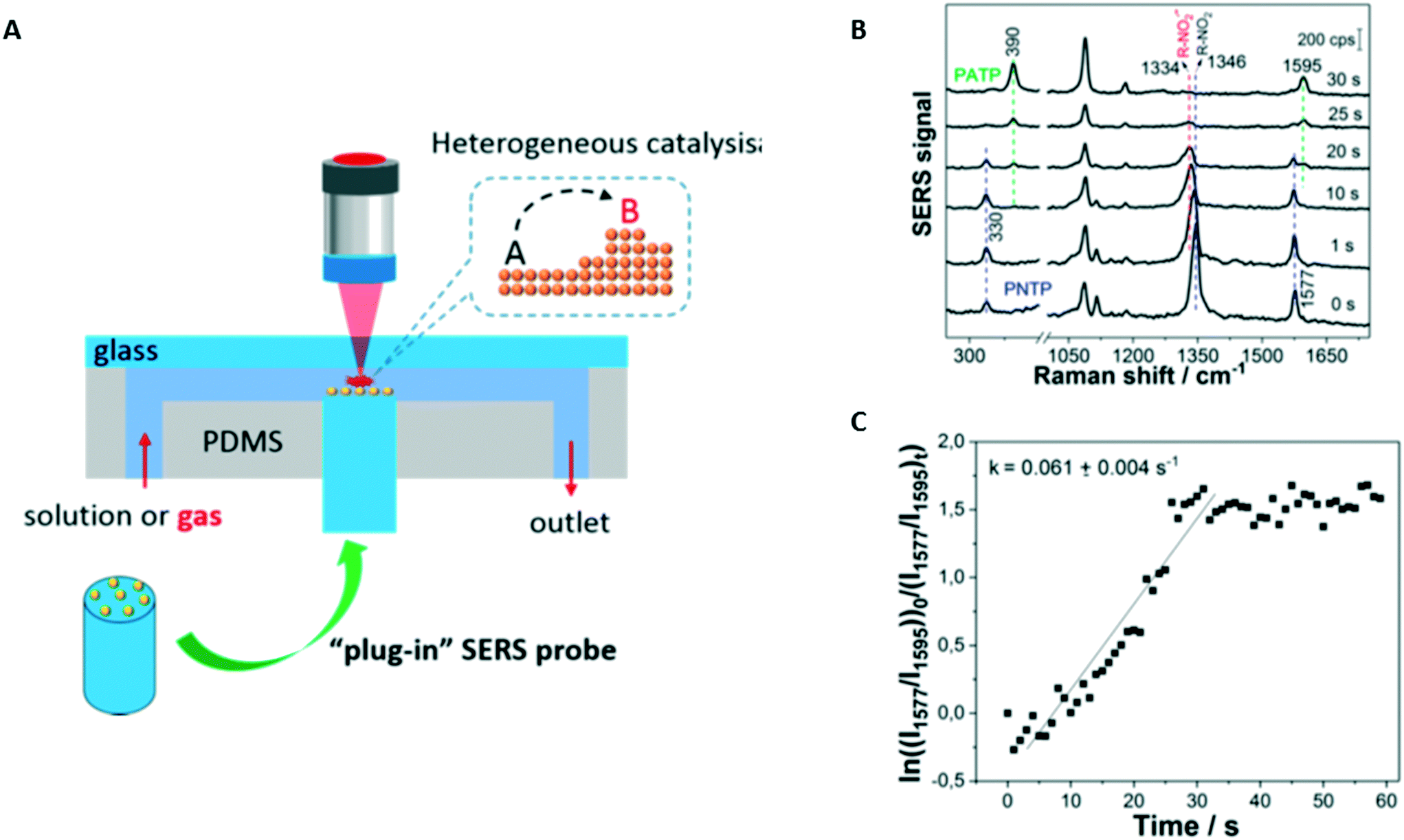 | ||
| Fig. 9 (A) Schematic of the whole plug-in optofluidic platform for monitoring of nanoparticle-catalyzed reactions in a microfluidic platform. (B) SERS spectra recorded during the catalytic reduction of PNTP on immobilized gold nanoparticles in an aqueous NaBH4 solution at different times. (C) Determination of the rate constant for the reduction of PNTP using the relative concentration of PNTP and PATP. Quantification is achieved by comparing the intensities of their characteristic bands at 1577 and 1595 cm−1 (λexcitation of 633 nm, intensity of 3 kW cm−2, acquisition time of 1 s). Reprinted (adapted) with permission from Zhang, Z. et al.222 Copyright (2018) American Chemical Society. | ||
3.3 In situ characterization of nanoparticles in microfluidic systems
For in situ characterization of nanoparticles, it is most important to characterize properties such as size, density, composition and atomic structure, as shown in Fig. 3. XAS is required especially for the composition and atomic structure of NPs. With XAS it is possible to probe single atoms and atom clusters. Another advantage of XAS in the characterization of synthesized NPs is the great time resolution that can be achieved. As an example, XANES was used to monitor the reduction of Au3+ to metallic gold within the first 2 ms of the formation.26 With EXAFS the growth rate can be monitored by measuring the evolution of size of the formed NPs over time.26,62An alternative to study the size of the synthesized NPs is UV-vis,118 see Fig. 3. The plasmon absorption peak observed in UV-vis analysis is dependent on the size of the nanoclusters.118 In order to characterize the size and shape small angle X-ray scattering (SAXS) can also be used.32 It is shown that in general UV-vis data for size characterization lead to more uncertainties than SAXS analysis. However, UV-vis is much easier to use in comparison to SAXS experiments which need synchrotron facilities, as mentioned before.
An example of the setup and the UV-vis data for various sizes of synthesized Ag NPs is shown in Fig. 10. Here the shift (and broadening) of the absorbance peak can be observed for various flow rates, indicating differently sized Ag NPs.
 | ||
| Fig. 10 UV-vis absorption spectra of silver nanoparticles made at different flow rates. Insets show the enlarged peak region (400–412 nm) and a summary of FWHMs of the absorbance of the Ag nanoparticles (in nm) at various volumetric flow rates (in mL min−1) used. Reprinted with permission from Lin, X. Z. et al.223 Copyright (2004) American Chemical Society. | ||
Furthermore, it was demonstrated that the formation of atomically precise 1–2 nm-sized copper clusters could be detected using UV-vis, although no-flow conditions were used.119 This shows the potential to use UV-vis in size characterization of NPs.118
3.4 Activity of supported catalyst nanoparticles in microreactors
Activity measurements of catalysts in microfluidic devices allow the study of the catalyst material under relevant conditions with well-controlled parameters such as temperature, flow rate, and pressure, see Table 4. As an example, it was previously reported that microfluidic reactors are capable of operating at temperatures and pressures up to 500 °C and 200 bar.150–152 Catalyst activity studies are, in contrast to the NP characterization discussed earlier, conducted on supported catalyst materials. The most common types of reactors are packed-bed and wall coated reactors. Catalyst particles are either loaded on larger porous supports, this can be oxide or polymer particles,79,112,113,116,123,127,128,130,131,148 or deposited as thin films on the reactor walls,108–111,114,115,117,124–126,133,134,136,138 as summarized in Table 4. Examples of wall-coated and packed-bed reactors are shown in Fig. 11.109,113,138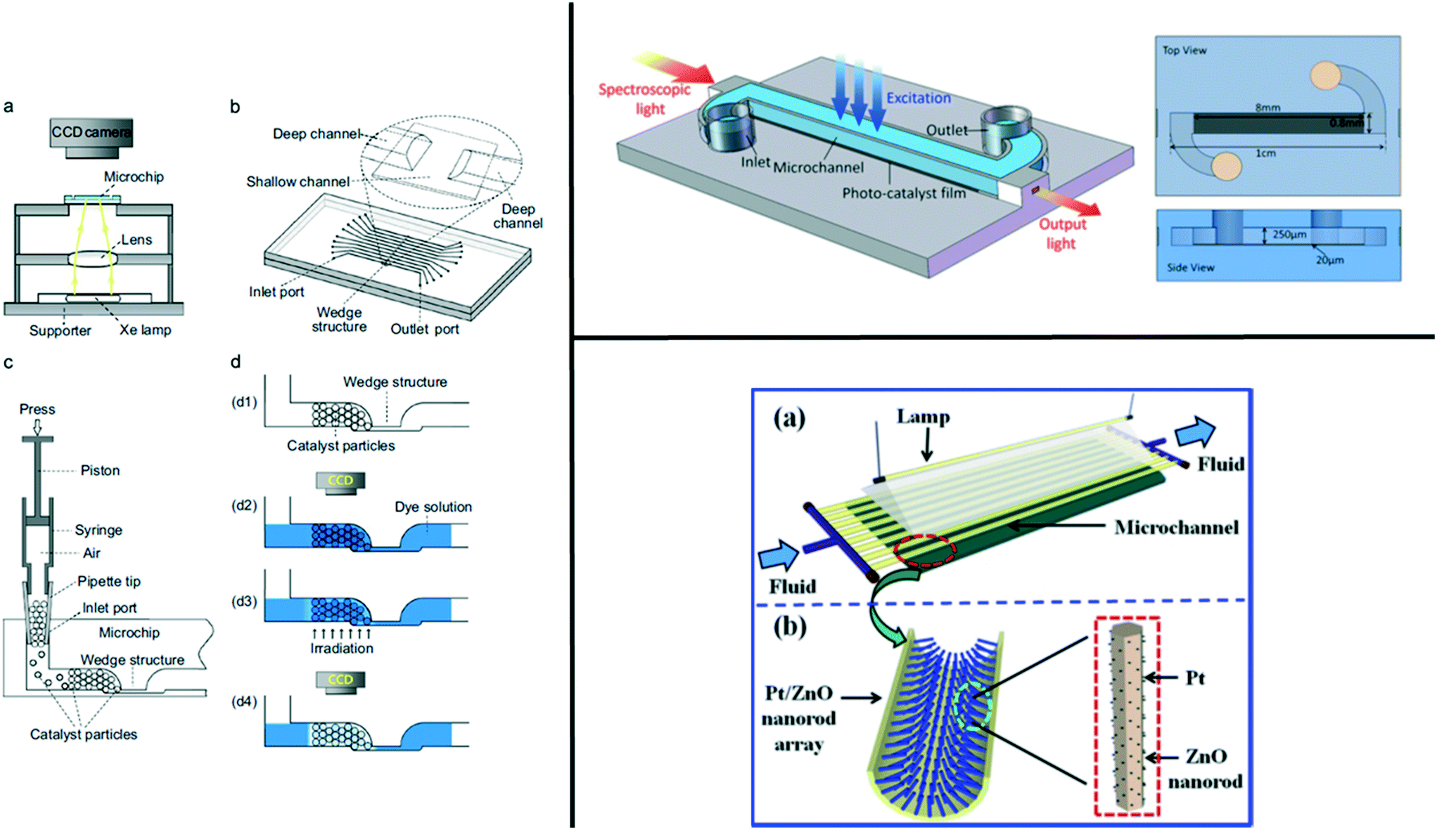 | ||
| Fig. 11 Overview of the two types of reactors (packed-bed and wall-coated) on the left: a packed-bed reactor in a glass–glass reactor with (a) the setup of the microchip-based photocatalyst screening system. (b) Schematic diagram of the multi-channel array chip with a wedge structure in each channel. (c) Schematic diagram of the catalyst loading operation. (d) Illustration of the catalyst screening procedure. (d1) Loading catalyst particles in the microchannel to form the column; (d2) introducing MB solution into the channel and recording the initial channel image using the CCD camera; (d3) MB degradation under irradiation of UV-light; and (d4) recording the channel image after a definite reaction time (not to scale). Reprinted from Zhang, H. et al.224 Copyright (2013) with permission from Elsevier. On the top right: a wall-coated reactor showing the schematic diagram of the fabricated microreactor. Reprinted with permission from Li, Y. et al.225 Copyright (2016) Nature Scientific reports. Subject to creative commons license: https://creativecommons.org/licenses/by/4.0/legalcode. On the bottom right: a wall-coated capillary reactor with (a) the schematic diagram of the microreactor modified with Pt/ZnO nanorod arrays for photodegradation of phenol, (b) schematic diagram of Pt/ZnO nanorod arrays on the inner wall of the microreactor. Reprinted from Zhang, Q. et al.226 Copyright (2013) with permission from Elsevier. | ||
In a packed-bed reactor, a large number of particles are used to make up the bed. This averages out the catalytic performance hindering the information at the single particle level.127 Packed-bed reactors have a large pressure drop over the reactor bed, although an inventive solution was found127,128 where instead of elongating the packed-bed, shorter parallel beds were used in a so-called cross-flow packed-bed reactor.
Sizes of supported NPs used in packed-bed reactors are between 20 and 120 micron as found.113,130 Packed-bed reactors have large effective areas compared to wall-coated reactors. In packed-bed reactors, the supported catalyst material can be placed either in a microfluidic chip, often consisting of silicon–silicon,108 glass–silicon,123,125,127,128,130,136,148 glass–glass,113,126,135 PDMS–glass,117 and PDMS–PDMS,138 or in a piece of tubing/capillary79,109–112,114–116,124,129,131–134 to form a microreactor. All the aforementioned examples are summarized in Table 4. One of the main reasons why the characterization of heterogeneous catalysts using microfluidics is still used relatively little is the difficulty to incorporate the catalysts in the microreactor.153 To overcome these issues, both zeolites and metal organic frameworks (MOFs) are excellent options. Zeolites are silica/alumina structures with both micro- and nanopore structures. The spatial conformation of the zeolite pores is highly dependent on their synthesis conditions, as discussed in section 2.1. Zeolites are used in acid-based (Brønsted and Lewis acid sites) catalysis. Furthermore, zeolites can be used as a support for catalytic nanoparticles, as shown in ref. 153–155, where Pt, Pd, and Cu or Ce oxides have been incorporated in a zeolite framework for heterogeneous catalytic microreactors. MOFs are highly porous structures with a very high surface to volume ratio. MOFs are built from metal ions or clusters that are linked together by organic ligands.156 The synthesis of MOFs is very versatile where the zeolite-like, porous structure can be tuned. To date, more than a thousand structures have been synthesized.157 In recent work, MOFs have been used inside microreactors, building both capillary reactors loaded with MOFs157,158 and highly porous glass fiber membranes156 and spongelike159 supports containing MOFs in a microreactor. To the best of our knowledge, in situ or in-line characterization has not yet been reported with MOFs inside a microreactor. All characterization methods found were performed offline with GC.
Control of temperature both spatially and in time allows for a more detailed study of kinetics and is necessary to mimic relevant reaction conditions in large reactors. On-chip reactors have the advantage of incorporating mixing modules135 followed by hot reaction zones, by using heater elements, on the chip.125,150 Silicon–glass microreactors, for example, can be fabricated with integrated heaters allowing rapid and accurate control of the temperature,123 as well as steep gradients, rapid cycling, and precise local heating, however, cleanroom facilities are needed. On the other hand, capillary reactors are simple and easier to fabricate.79,109–112,114–116,124,129,131–134 However, external heaters, such as oil baths, electrical heaters or ovens, have to be used in combination with these capillary reactors. This makes the heating process slower when adjusting or cycling the temperature, and spatial control is lost to a certain degree.79,124–126,130,132
Monitoring catalyst activity (or deactivation) over a longer period of time can be very useful. In situ catalyst deactivation studies show the importance of characterization of catalysts while they are at work,111,141,149,160 as shown in Fig. 7. However, due to the large intrinsic heterogeneities in a catalyst sample, it is not always sufficient to look at the bulk scale. Downsizing to a single particle level is very convenient and possible using microfluidics.
In situ Raman and in-line UV-vis spectroscopy were used to study the deposition and dissolution of asphaltenes in a packed-bed reactor filled with zeolite H-ZSM-5 with different silica/alumina ratios.149 Their results show the influence of the ratio on the deposition of asphaltenes in the pore structure, as measured with Raman spectroscopy. Dissolution of asphaltenes and their aromatic sheet sizes when xylene is pumped through the zeolite pores have been measured with UV-vis, see Fig. 12.149
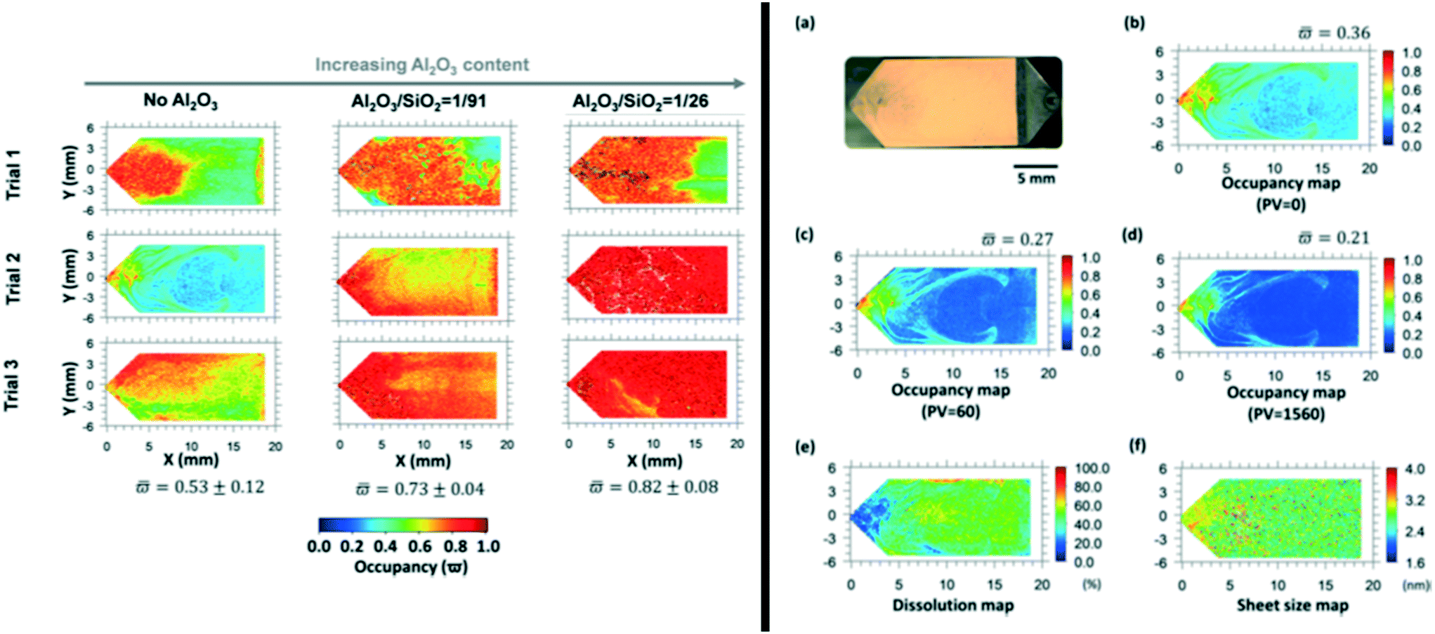 | ||
| Fig. 12 On the left: occupancy maps of asphaltenes deposited within the μPBR acquired by Raman spectroscopy. Both datasets illustrate the influence of the Al2O3/SiO2 ratio, showing that a higher ratio results in more asphaltene coverage indicated by the red color. On the right: (a) optical image of asphaltene deposition in the μPBR without the presence of zeolites (trial 2). Bed occupancy map of the μPBR after injection of different pore volumes of xylenes, (b) before injection of xylenes, (c) after injection of 60 pore volume of xylenes, and (d) after injection of 1560 pore volume of xylenes. The color change from light blue to dark blue in (b) to (d) indicates the dissolution of asphaltenes from the catalyst. Panel (e) shows a dissolution map, where green and red colours show areas of high dissolution and panel (f) shows a sheet size map of the aromatic asphaltene sheets between 1.6 and 4 nm. Both panels are reprinted (adapted) with permission from Chen, W. et al.227 Copyright (2018) American Chemical Society. | ||
A few studies also focus on long-term catalyst performance and deactivation,16,109–111 some of those studies extending over 100 and 120 h.109,110 By combining synchrotron-based IR and XAS measurement, as done by Gross et al. 2014,116 reactant depletion, product formation and changes in the catalyst during the reaction could be monitored.
3.5 Characterization method overview
In Table 5 an overview of various characterization methods, namely infrared, UV-vis, Raman, gas chromatography (GC)-mass spectrometry (MS), X-ray absorption spectroscopy (XAS), and nuclear magnetic resonance (NMR), and their use in combination with microfluidics is listed. These methods have been explored to investigate reaction intermediates and process yields, as well as selectivity, activity and stability of catalyst materials. Key features, such as speed, spatial resolution and chemical information obtained, are listed, and the foreseen limitations and their compatibility with microfluidics are stated.| Key feature | Infrared | UV-vis | Raman | GC/MS | XAS | NMR |
|---|---|---|---|---|---|---|
| a Typical speeds given in reviews. Please note that the speed is also dependent on the concentration that is used and the sensitivity of the machine. b Typical spatial resolution reported depending on the combination of chemical information needed and the catalyst material.169 | ||||||
| Speeda | Scan speed of 400 Hz for FTIR with a quantum cascade laser162 | Scan speed of 0.5 Hz (ref. 163) | Scan times of 30 ms for coherent anti-Stokes Raman scattering (CARS) up to 100 s (ref. 164) | On-line analysis can go up to 650 scans/s (ref. 165) | Reported speeds from ∼10 fs to ms (ref. 166 and 167) | Broad range of scan rates possible from the nanosecond to second range168 |
| Spatial resolutionb | ∼3 μm up to mm range169 | ∼1 μm up to mm range169 | ∼0,5 μm for coherent anti-Stokes Raman scattering (CARS)169 | N.A. | 15 nm–15 μm (ref. 116, 129 and 169) | Ranging from mm (ref. 131) to ∼20 μm (ref. 112) |
| Chemical information | Chemical compound information by probing intra-molecular vibrations | Chemical compound information via electronic transitions | Chemical compound information by probing intra-molecular vibrations | Chemical composition of feed | Chemical compound information via bond distance, oxidation state, coordination number, and chemical elemental information | Chemical compound information via chemical shifts of elements present and the relative magnetic interactions between them |
| Limitations | Incompatible with water. Limited to several types of chemical bonds | Incompatible with borosilicate due to absorption of light; molecular fingerprinting is difficult to broad overlapping absorption bands | Low efficiency of normal Raman scattering (no SERS or CARS) results in long scanning times164 | No operando or in situ information possible. Only outlet products can be analyzed | Synchrotron facilities needed, although lab-based XAS methods are becoming increasingly popular | Some nuclei require long acquisition times |
| Minimum sample volume needed | Complex data analysis | |||||
| Compatibility | + Good compatibility with microfluidics working with water makes the choice of solvents more limited. | + Good compatibility with microfluidics. The scan time needed for a clear signal. Working in flow or droplets can influence this. | + Good compatibility with microfluidics. Often enhancement is needed to obtain a large enough signal on chip. Enhancement also reduces scan speed and improves temporal information | − The need for relatively large sample volumes and the fact that only outlet products can be analyzed make it not always useful, although still detailed and valuable information can be obtained | + Good compatibility due to small reactor volumes | + H-NMR mostly used and compatible due to longer scan time needed for other types, such as C-NMR |
3.6 Conclusions
Currently, it has been shown that many analysis techniques are available to characterize both catalyst nanoparticles and supported catalyst materials in situ in a microfluidic device. For analysis of formed products at the outlet of a microreactor often GC and MS are used. The limit of these techniques, however, is that no information along the length of the reactor can be obtained. Short-lived intermediates which only exist close to the catalyst cannot be detected with these techniques. In order to study the catalyst performance at multiple spots in a microreactor, in situ spectroscopic techniques such as UV-vis, IR, RS, NMR, and XAS are used.For nanoparticle characteristics such as size, growth, and composition XAS and UV-vis are used, where mostly XAS is used to characterize the crystal structure, oxidation state, bond distance, and coordination number.
Characterization of the activity and deactivation of the supported catalyst material is mostly conducted in packed-bed reactors with multiple particles producing ensemble averages. The observed techniques are well suitable in combination with microfluidics. Locally formed products, differences in activity along a catalyst bed, turnover frequencies, and even the chemical state of the catalysts themselves are measurable using these techniques.
4 Conclusions and perspectives
Microfluidics has been used to enhance the control over chemical and physical conditions during catalytic NP synthesis. The ability to precisely control the temperature and reactant concentrations has led to very homogeneous particle synthesis in terms of shape and composition, especially for metallic particles. However, little has been done in microfluidics regarding bimetallic and zeolite nanoparticles, and regarding the integration of catalyst NPs in supporting microparticles.Progress in synthesis is coupled with the advances in characterization. The activity of supported catalysts is often studied with GC or MS at the output of the microfluidic chip, but the use of spatially resolved methods enables the detection of short-lived intermediates which exist only close to the catalyst. UV-vis analysis and XAS are also used to measure the physical and chemical characteristics of the catalyst NPs such as the size, composition, crystal structure or coordination number. If the NPs are fixed in a packed bed, these methods also enable the study of the activity and deactivation of the catalyst NPs.
The recent development of microfluidic tools opens new perspectives for synthesis and characterization of catalytic NPs, and also to study the coupling between convection, reaction and diffusion in the complex structures that are industrial catalytic porous microparticles. These perspectives are presented in the next sections.
4.1 Future perspectives on particle synthesis
As stated in the first part of this review, using microfluidics for particle synthesis is far from its full potential. This section tries to foresee the future paths of microfluidics as a tool to synthesise catalyst NPs and other catalytic structures such as zeolites or catalyst supports.Bimetallic NPs have been shown to have great potential for catalysis. It is known that the structure and the arrangement of the two metals have a great impact on the catalytic properties of such NPs,174 and that very precise assembly is possible when the synthesis conditions are controlled.175 Therefore, the use of calibrated microfluidic droplets as microreactors could enable very fine control on the synthesis conditions and hence on the final size and structure of such particles to optimize their catalytic activity.
Zeolites used in the industry often require high temperatures and long reaction times and their synthesis has not been fully investigated in microfluidics yet. Moreover, the model conditions offered by microfluidics could enable a precise study of the effect of mass and heat transfer on the zeolite structure that could be later used to optimize batch synthesis.
A controlled porosity of the catalyst support is essential to enable an increase of the contact area with the reaction media while preserving an efficient mass transfer through the pores. The control of the substrate porosity can also be further improved by implementing microfluidic methods that have been shown to be efficient for bulk materials. The first method to produce such a porous medium consists of triggering a chemical reaction which produces gas and solidifies the reaction media.176 Despite its simplicity, this method offers poor control on the pore size and structure. The second method presented here is the use of NPs as a template that are later dissolved to pattern the material.177 In this approach, the pores consist of the space that was previously occupied by the particles, and are therefore easy to control. Compact assemblies of NPs can indeed be produced inside droplets to obtain spherical assemblies of controlled size and morphology.178 This approach seems promising to yield microparticles with controlled porosity and high contact area with the external media. The third approach presented is based on complex liquids that can be solidified during the process of phase separation to obtain a material exhibiting a continuous network of pores of controlled size.179 The conditions of phase separation leading to continuous pore networks, referred to as “spinodal decomposition”, have been implemented in microfluidic devices to produce porous fibres and particles stabilized by NPs of silica adsorbing at the interface.180 Such binary systems, called “bijels”, experience a phase separation and are stabilized by NPs. The bottom-up approaches that rely on particle assembly or phase separation require a high level of control over the chemical and physical conditions. These conditions must indeed be homogeneous and reproducible, which calls for smaller reactors, as microfluidics can offer.
Parallel microfluidic channels tend to interact with each other due to the variation of the pressure along the channels,181 leading to varying flow rates and non-uniform droplet generation. However, chips have been recently developed to parallelize the production of droplets with good monodispersity by minimizing the flow rate variation182 or by using emulsification processes that do not depend on the flow rate.183–185 With this technology, relatively large quantities of catalysts could be synthesized with optimal control of the reaction conditions, which could be used to synthesise NPs or catalyse reactions in microfluidic reactors.
4.2 Perspectives on catalyst characterization in microfluidics
Biology has found in microfluidics an efficient way to study individual cells from large populations.186 By isolating individual cells in single droplets, they can be characterized individually at high throughput, allowing the analysis of large samples without losing the information about each cell. Several reviews focus on droplet-based microfluidics187 and its applications to biology, chemistry and nanotechnology.188 The need of biologists for analysis of individual elements in a large sample is very similar to the necessity for chemists to follow the evolution of individual catalyst particles. Although nanocatalysts are considerably smaller than cells, they are often embedded in porous microparticles with sizes from one to a few tens of micrometers, such as fluid catalytic cracking particles,155 or olefin polymerization catalysts. Under these conditions, some parallels can be made between cell analysis and catalyst analysis. Some microfluidic tools that have been developed for biology and could be used for catalysis are presented in the next sections.Very similar challenges were addressed in biology and thus, different solutions were developed. The classical method consists of isolating cells in different droplets to facilitate their manipulation, storage and analysis. Moreover, for cells as for catalyst particles, evolution can be slow and observation of significant variations can require a long time.
For very long-term processes, droplets containing cells/particles can be extracted from the chip, incubated and injected into a new one later.196 However, when possible, in order to limit the transfer of the emulsion between chips, droplets are stored directly inside the systems.197
In some cases, it can be interesting to vary the chemical composition of the droplets to screen various incubation conditions. It is then necessary to identify the different droplets to monitor the individual evolution of the cells/aging of the particles. To keep track of droplets, microscopic tags have been developed to enable later reading of their content and correlate the different measurements performed over time.108,192,209–211
It has also been shown that by confining the droplets in a line in capillaries or tubing, it is possible to keep track of the content of each droplet without tagging them and individually access them. This has been used for instance to study the proliferation of different cell populations over time.212 Finally, droplets can also be trapped with some obstacles inside microfluidics chips, which enables an accurate knowledge of the position of every droplet.194
It must be noted here that an important difference between cells and particles is their density: while cells have a density close to water, catalyst particles are significantly denser and therefore settle faster, which can lead to clogging of the channels. Nevertheless, these studies of cells pave the way toward the analysis of individual catalyst particle ageing.
4.3 Perspectives for fundamental understanding
The structure of industrial catalyst particles is complex and consists of various necessary properties such as: porosity, mechanical stability and catalytic activity of the particles.213 The mass and heat transfers inside these particles and the reaction medium are only partially understood yet. Further studies are limited by the difficulty of analysing single catalyst particles during reactions.An in-depth understanding of the mass and heat transfers inside the particles could be reached by studying model assemblies of their main constitutive elements. A 2D model network of pores and catalysts could be incorporated inside a microfluidic chip to control the input reactants and analyse the product output. This could enable the mapping of the temperature and product concentration inside the pore network. A similar approach has been used to study the phenomenon occurring when oil is pushed out a porous soil by water. A model network of pores was built inside a microfluidic chip, allowing direct observation of the phenomena occurring during oil recovery.214,215 However, to our knowledge such a method has not been transposed to the study of transport inside the pores of catalyst particles yet.
5 Outlook
All the progress of the last decades in the field of catalyst synthesis and on-chip material characterization brought a lot of new perspectives to obtain better control over catalyst material synthesis and their function. The advantages of microfluidics in terms of chemical engineering could be used to further improve the control over the nanostructure and porosity of catalyst materials. Moreover, the tools that could enable the synthesis in even smaller droplets were presented and it was illustrated how parallelization of the devices could maintain the throughput despite the smaller size of the reactors. Based on the development of single-cell microfluidic analysis, sorting and long-term deactivation studies of individual catalysts seem to be within reach. Finally, a fundamental approach inspired by the work on enhanced-oil-recovery could enable an in-depth understanding of the mass and heat transfer in reactive porous media constituting heterogeneous catalyst particles.6 Acronyms
NPs stands for nanoparticles, NSs for nanostars, NRs for nanorods, NCs for nanocubes, RT for room temperature, NS for not-specified, AA for ascorbic acid, SC for sodium citrate, SA for sodium aluminate, PVP for poly(N-vinyl-2-pyrrolidone), THF for tetrahydrofuran, CTABr for cetyltrimethylammonium bromide, BMIM-Tf2N for 1-butyl-3-methylimidazolium bis(triflylmethyl-sulfonyl)imide, BMIM-BF4 for 1-butyl-3-methylimidazolium tetrafluoroborate, BMIM-BH4 for 1-butyl-3-methylimidazolium tetrafluoroborate, TEOS for tetraethyl orthosilicate, CTAB for cetrimonium bromide, DMF for N,N-dimethylformamide, SB12 for propane-sulfonate, OPD for o-phenylenediamine, MUA for 11-mercaptoundecanoic acid, PEG for polyethylene glycol, TEG for triethylene glycol, EG for ethylene glycol, PDMS for polydimethylsiloxane, EFTE for ethylene tetrafluoroethylene, EA for ethyl acetate, PTFE for polytetrafluoroethylene, PFA for perfluoroalkoxyalkane, PVDF for polyvinylidene fluoride, MHA for mercaptohexanoic acid, and PP9 for perfluoromethyldecalin.Conflicts of interest
There are no conflicts of interest to declare.Acknowledgements
This work was supported by the Netherlands Centre for Multiscale Catalytic Energy Conversion (MCEC) an NWO Gravitation programme funded by the Ministry of Education, Culture and Science of the government of the Netherlands.References
- G. Centi and R. van Santen, Catalysis for Renewables: From Feedstock to Enerly Production, Wiley-VCH, Weinheim, 2007 Search PubMed.
- D. R. Gossett, W. M. Weaver, A. J. MacH, S. C. Hur, H. T. K. Tse and W. Lee, et al., Label-free cell separation and sorting in microfluidic systems, Anal. Bioanal. Chem., 2010, 397, 3249–3267 CrossRef CAS PubMed.
- I. V. C. Wyatt Shields, C. D. Reyes and G. P. López, Microfluidic cell sorting: a review of the advances in the separation of cells from debulking to rare cell isolation, Lab Chip, 2015, 15, 1230–1249 RSC.
- N. Hao, Y. Nie and J. X. J. Zhang, Microfluidic synthesis of functional inorganic micro−/nanoparticles and applications in biomedical engineering, Int. Mater. Rev., 2018, 63, 1–27 CrossRef.
- S. Marre and K. F. Jensen, Synthesis of micro and nanostructures in microfluidic systems, Chem. Soc. Rev., 2010, 39(3), 1183–1202 RSC.
- Y. Song, J. Hormes and C. S. S. R. Kumar, Microfluidic synthesis of nanomaterials, Small, 2008, 4(6), 698–711 CrossRef CAS PubMed.
- G. Luo, L. Du, Y. Wang, Y. Lu and J. Xu, Controllable preparation of particles with microfluidics, Particuology, 2011, 9(6), 545–558 CrossRef CAS.
- K. S. Elvira and A. J. deMello, The past, present and potential for microfluidic reactor technology in chemical synthesis, Nat. Chem., 2013, 5(11), 905–915 CrossRef CAS PubMed.
- T. A. Duncombe, A. M. Tentori and A. E. Herr, Microfluidics: Reframing biological enquiry, Nat. Rev. Mol. Cell Biol., 2015, 16(9), 554–567 CrossRef CAS PubMed.
- G. A. Somorjai and J. Y. Park, Molecular factors of catalytic selectivity, Angew. Chem., Int. Ed., 2008, 47(48), 9212–9228 CrossRef CAS PubMed.
- K. An and G. A. Somorjai, Size and Shape Control of Metal Nanoparticles for Reaction Selectivity in Catalysis, ChemCatChem, 2012, 4(10), 1512–1524 CrossRef CAS.
- P. Mäki-Arvela and D. Y. Murzin, Effect of catalyst synthesis parameters on the metal particle size, Appl. Catal., A, 2013, 451, 251–281 CrossRef.
- A. M. Gadalla and B. Bower, The role of catalyst support on the activity of nickel for reforming methane with CO2, Chem. Eng. Sci., 1988, 43(11), 3049–3062 CrossRef CAS.
- J. Ftouni, J.-S. Girardon, M. Penhoat, E. Payen and C. Rolando, Gold nanoparticle synthesis in microfluidic systems and immobilisation in microreactors designed for the catalysis of fine organic reactions, Microsyst. Technol., 2012, 18(2), 151–158 CrossRef.
- J. Ftouni, M. Penhoat, A. Addad, E. Payen, C. Rolando and J.-S. Girardon, Highly controlled synthesis of nanometric gold particles by citrate reduction using the short mixing, heating and quenching times achievable in a microfluidic device, Nanoscale, 2012, 4(15), 4450–4454 RSC.
- S. Lin, K. Lin, D. Lu and Z. Liu, Preparation of uniform magnetic iron oxide nanoparticles by co-precipitation in a helical module microchannel reactor, Biochem. Pharmacol., 2017, 5(1), 303–309 CAS.
- E. J. Roberts, S. E. Habas, L. Wang, D. A. Ruddy, E. A. White and F. G. Baddour, et al., High-Throughput Continuous Flow Synthesis of Nickel Nanoparticles for the Catalytic Hydrodeoxygenation of Guaiacol, ACS Sustainable Chem. Eng., 2017, 5(1), 632–639 CrossRef CAS.
- P. S. Lee, S. V. Garimella and D. Liu, Investigation of heat transfer in rectangular microchannels, Int. J. Heat Mass Transfer, 2005, 48(9), 1688–1704 CrossRef CAS.
- G. L. Morini, Single-phase convective heat transfer in microchannels: A review of experimental results, Int. J. Therm. Sci., 2004, 43(7), 631–651 CrossRef.
- P. Rosa, T. G. Karayiannis and M. W. Collins, Single-phase heat transfer in microchannels: The importance of scaling effects, Appl. Therm. Eng., 2009, 29(17–18), 3447–3468 CrossRef CAS.
- B. Palm, Heat transfer in rectangular microchannels, Microscale Thermophys. Eng., 2001, 5, 155–175 CrossRef CAS.
- Á. I. López-Lorente, M. Valcárcel and B. Mizaikoff, Continuous flow synthesis and characterization of tailor-made bare gold nanoparticles for use in SERS, Microchim. Acta, 2014, 181(9–10), 1101–1108 CrossRef.
- H. SadAbadi, S. Badilescu, M. Packirisamy and R. Wüthrich, Integration of gold nanoparticles in PDMS microfluidics for lab-on-a-chip plasmonic biosensing of growth hormones, Biosens. Bioelectron., 2013, 44(1), 77–84 CrossRef CAS PubMed.
- A. Heuer-Jungemann, N. Feliu, I. Bakaimi, M. Hamaly, A. Alkilany and I. Chakraborty, et al., The role of ligands in the chemical synthesis and applications of inorganic nanoparticles, Chem. Rev., 2019, 119(8), 4819–4880 CrossRef CAS PubMed.
- J. Il Park, A. Saffari, S. Kumar, A. Günther and E. Kumacheva, Microfluidic, Synthesis of Polymer and Inorganic Particulate Materials, Annu. Rev. Mater. Res., 2010, 40(1), 415–443 CrossRef CAS.
- G. Tofighi, H. Lichtenberg, J. Pesek, T. L. Sheppard, W. Wang and L. Schöttner, et al., Continuous microfluidic synthesis of colloidal ultrasmall gold nanoparticles: in situ study of the early reaction stages and application for catalysis, React. Chem. Eng., 2017, 2, 876–884 RSC.
- L. Wang, S. Ma, B. Yang, W. Cao and X. Han, Morphology-controlled synthesis of Ag nanoparticle decorated poly(o-phenylenediamine) using microfluidics and its application for hydrogen peroxide detection, Chem. Eng. J., 2015, 268, 102–108 CrossRef CAS.
- H. Yagyu, Y. Tanabe, S. Takano and M. Hamamoto, Continuous flow synthesis of monodisperse gold nanoparticles by liquid-phase reduction method on glass microfluidic device, Micro Nano Lett., 2017, 12(8), 536–539 CrossRef CAS.
- M. Jiao, J. Zeng, L. Jing, C. Liu and M. Gao, Flow synthesis of biocompatible Fe3O4nanoparticles: Insight into the effects of residence time, fluid velocity, and tube reactor dimension on particle size distribution, Chem. Mater., 2015, 27(4), 1299–1305 CrossRef CAS.
- S. E. Lohse, J. R. Eller, S. T. Sivapalan, M. R. Plews and C. J. Murphy, A simple millifluidic benchtop reactor system for the high-throughput synthesis and functionalization of gold nanoparticles with different sizes and shapes, ACS Nano, 2013, 7(5), 4135–4150 CrossRef CAS.
- H. Jun, T. Fabienne, M. Florent, P. E. Coulon, M. Nicolas and S. Olivier, Understanding of the size control of biocompatible gold nanoparticles in millifluidic channels, Langmuir, 2012, 28(45), 15966–15974 CrossRef CAS.
- J. Polte, R. Erler, A. F. Thünemann, S. Sokolov, T. T. Ahner and K. Rademann, et al., Nucleation and Growth of Gold, ACS Nano, 2010, 4(2), 1076–1082 CrossRef CAS PubMed.
- L. Xu, C. Srinivasakannan, J. Peng, M. Yan, D. Zhang and L. Zhang, Microfluidic reactor synthesis and photocatalytic behavior of Cu@Cu2O nanocomposite, Appl. Surf. Sci., 2015, 331, 449–454 CrossRef CAS.
- L. Xu, C. Srinivasakannan, J. Peng, L. Zhang and D. Zhang, Synthesis of Cu-CuO nanocomposite in microreactor and its application to photocatalytic degradation, J. Alloys Compd., 2017, 695, 263–269 CrossRef CAS.
- N. Hayashi, Y. Sakai, H. Tsunoyama and A. Nakajima, Development of ultrafine multichannel microfluidic mixer for synthesis of bimetallic nanoclusters: Catalytic application of highly monodisperse AuPd nanoclusters stabilized by poly(N -vinylpyrrolidone), Langmuir, 2014, 30(34), 10539–10547 CrossRef CAS PubMed.
- R. Baber, L. Mazzei, N. T. K. Thanh and A. Gavriilidis, Synthesis of silver nanoparticles in a microfluidic coaxial flow reactor, RSC Adv., 2015, 5(116), 95585–95591 RSC.
- A. Abou-Hassan, S. Neveu, V. Dupuis and V. Cabuil, Synthesis of cobalt ferrite nanoparticles in continuous-flow microreactors, RSC Adv., 2012, 2(30), 11263–11266 RSC.
- K. N. Han, C. A. Li, M. P. N. Bui, X. H. Pham, B. S. Kim and Y. H. Choa, et al., On-chip electrochemical detection of bio/chemical molecule by nanostructures fabricated in a microfluidic channel, Sens. Actuators, B, 2013, 177, 472–477 CrossRef CAS.
- L. Hafermann and J. M. Köhler, Photochemical Micro Continuous-Flow Synthesis of Noble Metal Nanoparticles of the Platinum Group, Chem. Eng. Technol., 2015, 38(7), 1138–1143 CrossRef CAS.
- T. Ishizaka, A. Ishigaki, H. Kawanami, A. Suzuki and T. M. Suzuki, Dynamic control of gold nanoparticle morphology in a microchannel flow reactor by glucose reduction in aqueous sodium hydroxide solution, J. Colloid Interface Sci., 2012, 367(1), 135–138 CrossRef CAS PubMed.
- D. H. Napper, Colloid Stability, Ind. Eng. Chem. Prod. Res. Dev., 1970, 9(4), 467–477 CrossRef CAS.
- D. H. Napper, Steric stabilization, J. Colloid Interface Sci., 1977, 58(2), 390–407 CrossRef CAS.
- T. A. Witten, P. A. Pincus and P. A. Pincus, Colloid Stabilization by Long Grafted Polymers, Macromolecules, 1986, 19(10), 2509–2513 CrossRef CAS.
- H. Hu, J. H. Xin, H. Hu, X. Wang, D. Miao and Y. Liu, Synthesis and stabilization of metal nanocatalysts for reduction reactions - A review, J. Mater. Chem. A, 2015, 3(21), 11157–11182 RSC.
- J. A. Lopez-Sanchez, N. Dimitratos, C. Hammond, G. L. Brett, L. Kesavan and S. White, et al., Facile removal of stabilizer-ligands from supported gold nanoparticles, Nat. Chem., 2011, 3(7), 551–556 CrossRef CAS PubMed.
- M.-C. Daniel and D. Astruc, Gold Nanoparticles: Assembly, Supramolecular Chemistry, Quantum-Size-Related Properties, and Applications toward Biology, Catalysis, and Nanotechnology, Chem. Rev., 2004, 104(1), 293–346 CrossRef CAS PubMed.
- P. J. Kitson, M. H. Rosnes, V. Sans, V. Dragone and L. Cronin, Configurable 3D-Printed millifluidic and microfluidic “lab on a chip” reactionware devices, Lab Chip, 2012, 12, 3267–3271 RSC.
- G. Tofighi, H. Lichtenberg, J. Pesek, T. L. Sheppard, W. Wang and L. Schöttner, et al., Continuous microfluidic synthesis of colloidal ultrasmall gold nanoparticles: in situ study of the early reaction stages and application for catalysis, React. Chem. Eng., 2017, 2, 876–884 RSC.
- M. V. Bandulasena, G. T. Vladisavljević, O. G. Odunmbaku and B. Benyahia, Continuous synthesis of PVP stabilized biocompatible gold nanoparticles with a controlled size using a 3D glass capillary microfluidic device, Chem. Eng. Sci., 2017, 171, 233–243 CrossRef CAS.
- L. Uson, V. Sebastian, M. Arruebo and J. Santamaria, Continuous microfluidic synthesis and functionalization of gold nanorods, Chem. Eng. J., 2016, 285, 286–292 CrossRef CAS.
- Q. Fu, Y. Sheng, H. Tang, Z. Zhu, M. Ruan and W. Xu, et al., Growth Mechanism Deconvolution of Self- Growth Mechanism Deconvolution of Self-Limiting Supraparticles Based on Micro fl uidic System, ACS Nano, 2015, 9(1), 172–179 CrossRef CAS PubMed.
- L. Gomez, V. Sebastian, S. Irusta, A. Ibarra, M. Arruebo and J. Santamaria, Scaled-up production of plasmonic nanoparticles using microfluidics: from metal precursors to functionalized and sterilized nanoparticles, Lab Chip, 2014, 14(2), 325–332 RSC.
- K. Sai Krishna, C. V. Navin, S. Biswas, V. Singh, K. Ham and G. L. Bovenkamp, et al., Millifluidics for time-resolved mapping of the growth of gold nanostructures, J. Am. Chem. Soc., 2013, 135(14), 5450–5456 CrossRef CAS PubMed.
- A. Sugie, H. Song, T. Horie, N. Ohmura, K. Kanie and A. Muramatsu, et al., Synthesis of thiol-capped gold nanoparticle with a flow system using organosilane as a reducing agent, Tetrahedron Lett., 2012, 53(33), 4457–4459 CrossRef CAS.
- M. Luty-Błocho, K. Fitzner, V. Hessel, P. Löb, M. Maskos and D. Metzke, et al., Synthesis of gold nanoparticles in an interdigital micromixer using ascorbic acid and sodium borohydride as reducers, Chem. Eng. J., 2011, 171(1), 279–290 CrossRef.
- K. Sugano, Y. Uchida, O. Ichihashi, H. Yamada, T. Tsuchiya and O. Tabata, Mixing speed-controlled gold nanoparticle synthesis with pulsed mixing microfluidic system, Microfluid. Nanofluid., 2010, 9(6), 1165–1174 CrossRef CAS.
- J. Polte, R. Erler, A. F. Thünemann, S. Sokolov, T. T. Ahner and K. Rademann, et al., Nucleation and Growth of Gold Nanoparticles Studied via in situ Small Angle X-ray Scattering at Millisecond Time Resolution, ACS Nano, 2010, 4(2), 1076–1082 CrossRef CAS PubMed.
- S. G. Pedro, M. Puyol, D. Izquierdo, Í. Salinas and J. Alonso, Group B, et al., Synthesis of MUA-protected gold nanoparticles in microfluidic devices with in situ UV-vis characterization. Conf Ibersensor November, Lisbon, 2010 Search PubMed.
- C. Bullen, M. J. Latter, N. J. D'Alonzo, G. J. Willis and C. L. Raston, A seedless approach to continuous flow synthesis of gold nanorods, Chem. Commun., 2011, 47(14), 4123–4125 RSC.
- S. Horikoshi, T. Sumi and N. Serpone, A Hybrid Microreactor/Microwave High-Pressure Flow System of a Novel Concept Design and its Application to the Synthesis of Silver Nanoparticles, Chem. Eng. Process., 2013, 73, 59–66 CrossRef CAS.
- H. Liu, J. Huang, D. Sun, L. Lin, W. Lin and J. Li, et al., Microfluidic biosynthesis of silver nanoparticles: Effect of process parameters on size distribution, Chem. Eng. J., 2012, 209, 568–576 CrossRef CAS.
- A. M. Karim, N. Al Hasan, S. Ivanov, S. Siefert, R. T. Kelly and N. G. Hallfors, et al. Synthesis of 1 nm Pd Nanoparticles in a Microfluidic Reactor: Insights from in Situ X-ray Absorption Fine Structure Spectroscopy and Small-Angle X-ray Scattering, J. Phys. Chem. C, 2015, 119(23), 13257–13267 CrossRef.
- H. Liang, Z. Wang, J. Wang, D. Huang, Y. Zhu and Y. Song, Synthesis of Fe(1-x)Znx@Zn(1-y)FeyOz nanocrystals via a simple programmed microfluidic process, Mater. Chem. Phys., 2017, 201, 156–164 CrossRef CAS.
- Y. Song, R. Li, Q. Sun and P. Jin, Controlled growth of Cu nanoparticles by a tubular microfluidic reactor, Chem. Eng. J., 2011, 168(1), 477–484 CrossRef CAS.
- L. Xu, C. Srinivasakannan, J. Peng, D. Zhang and G. Chen, Synthesis of nickel nanoparticles by aqueous reduction in continuous flow microreactor, Chem. Eng. Process., 2015, 93, 44–49 CrossRef CAS.
- R. Eluri and B. Paul, Synthesis of nickel nanoparticles by hydrazine reduction: Mechanistic study and continuous flow synthesis, J. Nanopart. Res., 2012, 14(4), 1–14 CrossRef.
- P. L. Suryawanshi, S. P. Gumfekar, P. R. Kumar, B. B. Kale and S. H. Sonawane, Synthesis of ultra-small platinum nanoparticles in a continuous flow microreactor, Colloid Interface Sci. Commun., 2016, 13, 6–9 CrossRef CAS.
- M. J. Hossain, H. Tsunoyama, M. Yamauchi, N. Ichikuni and T. Tsukuda, High-yield synthesis of PVP-stabilized small Pt clusters by microfluidic method, Catal. Today, 2012, 183(1), 101–107 CrossRef CAS.
- S. Abalde-Cela, P. Taladriz-Blanco, M. G. De Oliveira and C. Abell, Droplet microfluidics for the highly controlled synthesis of branched gold nanoparticles, Sci. Rep., 2018, 8, 2440–2446 CrossRef PubMed.
- L. L. Lazarus, C. T. Riche, B. C. Marin, M. Gupta, N. Malmstadt and R. L. Brutchey, Two-phase microfluidic droplet flows of ionic liquids for the synthesis of gold and silver nanoparticles, ACS Appl. Mater. Interfaces, 2012, 4(6), 3077–3083 CrossRef CAS PubMed.
- L. L. Lazarus, A. S.-J. Yang, S. Chu, R. L. Brutchey and N. Malmstadt, Flow-focused synthesis of monodisperse gold nanoparticles using ionic liquids on a microfluidic platform, Lab Chip, 2010, 10(24), 3377–3379 RSC.
- L. Xu, J. Peng, C. Srinivasakannan, L. Zhang, D. Zhang and C. Liu, et al., Synthesis of copper nanoparticles by a T-shaped microfluidic device, RSC Adv., 2014, 4(48), 25155–25159 RSC.
- L. Zhang, Y. Wang, L. Tong and Y. Xia, Seed-mediated synthesis of silver nanocrystals with controlled sizes and shapes in droplet microreactors separated by air, Langmuir, 2013, 29(50), 15719–15725 CrossRef CAS PubMed.
- L. Hafermann and K. J. Michael, Small gold nanoparticles formed by rapid photochemical flow-through synthesis using microfluid segment technique, J. Nanopart. Res., 2015, 17(2), 1–8 CrossRef CAS.
- Y. H. Kim, L. Zhang, T. Yu, M. Jin, D. Qin and Y. Xia, Droplet-based microreactors for continuous production of palladium nanocrystals with controlled sizes and shapes, Small, 2013, 9, 3462–3467 CrossRef CAS PubMed.
- K. Kumar, A. M. Nightingale, S. H. Krishnadasan, N. Kamaly, M. Wylenzinska-Arridge and K. Zeissler, et al., Direct synthesis of dextran-coated superparamagnetic iron oxide nanoparticles in a capillary-based droplet reactor, J. Mater. Chem., 2012, 22(11), 4704–4708 RSC.
- K. G. Lee, J. Hong, K. W. Wang, N. S. Heo, D. H. Kim and S. Y. Lee, et al., In VitroBiosynthesis of Metal Nanoparticles in Microdroplets, ACS Nano, 2012, 6(8), 6998–7008 CAS.
- L. Zhang, G. Niu, N. Lu, J. Wang, L. Tong and L. Wang, et al., Continuous and scalable production of well-controlled noble-metal nanocrystals in milliliter-sized droplet reactors, Nano Lett., 2014, 14(11), 6626–6631 CAS.
- X. Li, N. Visaveliya, L. Hafermann, G. A. Gross, A. Knauer and J. M. Köhler, Hierarchically structured particles for micro flow catalysis, Chem. Eng. J., 2017, 326, 1058–1065 CAS.
- D. V. Ravi Kumar, B. L. V. Prasad and A. A. Kulkarni, Segmented flow synthesis of Ag nanoparticles in spiral microreactor: Role of continuous and dispersed phase, Chem. Eng. J., 2012, 192, 357–368 CAS.
- V. Sebastian Cabeza, S. Kuhn, A. A. Kulkarni and K. F. Jensen, Size-Controlled Flow Synthesis of Gold Nanoparticles Using a Segmented Flow Micro fluidic Platform, Langmuir, 2012, 28(17), 7007–7013 CAS.
- D. Zhang, F. Wu, M. Peng, X. Wang, D. Xia and G. Guo, One-step, facile and ultrafast synthesis of phase- and size-controlled Pt-Bi intermetallic nanocatalysts through continuous-flow microfluidics, J. Am. Chem. Soc., 2015, 137(19), 6263–6269 CAS.
- Z. Wang, H. Fan, H. Liang, J. Ma, S. Li and Y. Song, et al., Microfluidic Synthesis and Characterization of FePtSn/C Catalysts with Enhanced Electro-Catalytic Performance for Direct Methanol Fuel Cells, Electrochim. Acta, 2017, 230, 245–254 CrossRef CAS.
- S. Tao, M. Yang, H. Chen, M. Ren and G. Chen, Microfluidic synthesis of Ag@Cu2O core-shell nanoparticles with enhanced photocatalytic activity, J. Colloid Interface Sci., 2017, 486, 16–26 CrossRef CAS.
- Z. H. Tian, Y. J. Wang, J. H. Xu and G. S. Luo, Intensification of nucleation stage for synthesizing high quality CdSe quantum dots by using preheated precursors in microfluidic devices, Chem. Eng. J., 2016, 302, 498–502 CrossRef CAS.
- Z. H. Tian, J. H. Xu, Y. J. Wang and G. S. Luo, Microfluidic synthesis of monodispersed CdSe quantum dots nanocrystals by using mixed fatty amines as ligands, Chem. Eng. J., 2016, 285, 20–26 CrossRef CAS.
- B. Swain, M. H. Hong, L. Kang, B. S. Kim, N. H. Kim and C. G. Lee, Optimization of CdSe nanocrystals synthesis with a microfluidic reactor and development of combinatorial synthesis process for industrial production, Chem. Eng. J., 2017, 308, 311–321 CrossRef CAS.
- J. Wang, H. Zhao, Y. Zhu and Y. Song, Shape-Controlled Synthesis of CdSe Nanocrystals via a Programmed Microfluidic Process, J. Phys. Chem. C, 2017, 121(6), 3567–3572 CrossRef CAS.
- I. Lignos, S. Stavrakis, A. Kilaj and A. J. deMello, Millisecond-Timescale Monitoring of PbS Nanoparticle Nucleation and Growth Using Droplet-Based Microfluidics, Small, 2015, 11(32), 4009–4017 CrossRef CAS PubMed.
- N. J. Carroll, P. F. Crowder, S. Pylypenko, W. Patterson, D. R. Ratnaweera and D. Perahia, et al., Microfluidic synthesis of monodisperse nanoporous oxide particles and control of hierarchical pore structure, ACS Appl. Mater. Interfaces, 2013, 5(9), 3524–3529 CrossRef CAS PubMed.
- N. Bchellaoui, Z. Hayat, M. Mami, R. Dorbez-Sridi and A. I. El Abed, Microfluidic-assisted Formation of Highly Monodisperse and Mesoporous Silica Soft Microcapsules, Sci. Rep., 2017, 7, 1–10 CrossRef CAS PubMed.
- Y. Nie, N. Hao and J. X. J. Zhang, Ultrafast Synthesis of Multifunctional Submicrometer Hollow Silica Spheres in Microfluidic Spiral Channels, Sci. Rep., 2017, 7(1), 1–9 CrossRef PubMed.
- I. Lee, Y. Yoo, Z. Cheng and H. K. Jeong, Generation of monodisperse mesoporous silica microspheres with controllable size and surface morphology in a microfluidic device, Adv. Funct. Mater., 2008, 18(24), 4014–4021 CrossRef CAS.
- L. Yu, Y. Pan, C. Wang and L. Zhang, A two-phase segmented microfluidic technique for one-step continuous versatile preparation of zeolites, Chem. Eng. J., 2013, 219, 78–85 CrossRef CAS.
- J. Ju, C. Zeng, L. Zhang and N. Xu, Continuous synthesis of zeolite NaA in a microchannel reactor, Chem. Eng. J., 2006, 116(2), 115–121 CrossRef CAS.
- Y. Pan, J. Yao, L. Zhang and N. Xu, Preparation of Ultrafine Zeolite A Crystals with Narrow Particle Size Distribution Using a Two-Phase Liquid Segmented Microfluidic Reactor, Ind. Eng. Chem. Res., 2009, 48(18), 8471–8477 CrossRef CAS.
- P. H. Hoang, K. B. Yoon and D. P. Kim, Synthesis of hierarchically porous zeolite A crystals with uniform particle size in a droplet microreactor, RSC Adv., 2012, 2(12), 5323–5328 RSC.
- M. Faustini, J. Kim, G. Jeong, J. Y. Kim, H. R. Moon and W. Ahn, et al., Microfluidic Approach toward Continuous and Ultrafast Synthesis of Metal − Organic Framework Crystals and Hetero Structures in Confined Microdroplets, J. Am. Chem. Soc., 2013, 135, 14619–14626 CrossRef CAS PubMed.
- D. Witters, N. Vergauwe, R. Ameloot, S. Vermeir, D. De Vos, R. Puers, B. Sels and J. Lammertyn, Digital Microfluidic High-Throughput Printing of Single Metal-Organic Framework Crystals, Adv. Mater., 2012, 24, 1316–1320 CrossRef CAS PubMed.
- J. D. Tice, H. Song, A. D. Lyon and R. F. Ismagilov, Formation of Droplets and Mixing in Multiphase Microfluidics at Low Values of the Reynolds and the Capillary Numbers, Langmuir, 2003, 19(22), 9127–9133 CrossRef CAS.
- R. O. Grigoriev, M. F. Schatz and V. Sharma, Chaotic mixing in microdroplets, Lab Chip, 2006, 6(10), 1369 RSC.
- A. M. Nightingale and J. C. De Mello, Microscale synthesis of quantum dots, J. Mater. Chem., 2010, 20(39), 8454–8463 RSC.
- J. Baek, Y. Shen, I. Lignos, M. G. Bawendi and K. F. Jensen, Multistage Microfluidic Platform for the Continuous Synthesis of III–V Core/Shell Quantum Dots, Angew. Chem., Int. Ed., 2018, 57(34), 10915–10918 CrossRef CAS PubMed.
- J. D. Rimer, M. Kumar, R. Li, A. I. Lupulescu and M. D. Oleksiak, Tailoring the physicochemical properties of zeolite catalysts, Catal. Sci. Technol., 2014, 4(11), 3762–3771 RSC.
- Y. Pan, J. Yao, L. Zhang, J. Ju, H. Wang and N. Xu, Rapid crystallization of silicalite nanocrystals in a capillary microreactor, Chem. Eng. Technol., 2009, 32(5), 732–737 CrossRef CAS.
- A. Dhakshinamoorthy, L. Zhaohui and H. Garcia, Catalysis and photocatalysis by metal organic framewoks, Chem. Soc. Rev., 2018, 47, 8134–8172 RSC.
- Y. Song, D. Cheng, L. Zhao, F. Cacho-Bailo, C. Téllez and J. Coronas, Microfluidic Synthesis of MOFs and MOF-Based Membranes, Microfluid Fundam Devices Appl., 2018, pp. 479–515 Search PubMed.
- S. Zhao, Y. Li, E. Stavitski, R. Tappero, S. Crowley and M. J. Castaldi, et al., Operando Characterization of Catalysts through use of a Portable Microreactor, ChemCatChem, 2015, 7(22), 3683–3691 CrossRef CAS.
- Q. Zhang, Q. Zhang, H. Wang and Y. Li, A high efficiency microreactor with Pt/ZnO nanorod arrays on the inner wall for photodegradation of phenol, J. Hazard. Mater., 2013, 254–255(1), 318–324 CrossRef CAS PubMed.
- Z. He, Y. Li, Q. Zhang and H. Wang, Capillary microchannel-based microreactors with highly durable ZnO/TiO2nanorod arrays for rapid, high efficiency and continuous-flow photocatalysis, Appl. Catal., A, 2010, 93(3–4), 376–382 CrossRef CAS.
- S. Hannemann, J. D. Grunwaldt, N. van Vegten, A. Baiker, P. Boye and C. G. Schroer, Distinct spatial changes of the catalyst structure inside a fixed-bed microreactor during the partial oxidation of methane over Rh/Al2O3, Catal. Today, 2007, 126(1–2), 54–63 CrossRef CAS.
- L.-S. Bouchard, S. R. Burt, M. S. Anwar, K. V. Kovtunov, I. V. Koptyung and A. Pines, NMR Imaging of Catalytic Hydrogenation in Microreactors with the Use of para-Hydrogen, Science, 2008, 319, 442–445 CrossRef CAS.
- H. Zhang, J. J. Wang, J. Fan and Q. Fang, Microfluidic chip-based analytical system for rapid screening of photocatalysts, Talanta, 2013, 116, 946–950 CrossRef CAS PubMed.
- A. L. Liu, Z. Q. Li, Z. Q. Wu and X. H. Xia, Study on the photocatalytic reaction kinetics in a TiO2nanoparticles coated microreactor integrated microfluidics device, Talanta, 2018, 182, 544–548 CrossRef CAS PubMed.
- J. Gmeiner, S. Behrens, B. Spliethoff and O. Trapp, Ruthenium Nanoparticles in High-Throughput Studies of Chemoselective Carbonyl Hydrogenation Reactions, ChemCatChem, 2016, 8(3), 571–576 CrossRef CAS.
- E. Gross, X. Z. Shu, S. Alayoglu, H. A. Bechtel, M. C. Martin and F. D. Toste, et al., In situ IR and X-ray high spatial-resolution microspectroscopy measurements of multistep organic transformation in flow microreactor catalyzed by Au nanoclusters, J. Am. Chem. Soc., 2014, 136(9), 3624–3629 CrossRef CAS PubMed.
- Z. Zhang, U. Gernert, R. F. Gerhardt, E. M. Höhn, D. Belder and J. Kneipp, Catalysis by Metal Nanoparticles in a Plug-In Optofluidic Platform: Redox Reactions of p-Nitrobenzenethiol and p-Aminothiophenol, ACS Catal., 2018, 8(3), 2443–2449 CrossRef CAS.
- X. Z. Lin, A. D. Terepka and H. Yang, Synthesis of silver nanoparticles in a continuous flow tubular microreactor, Nano Lett., 2004, 4(11), 2227–2232 CrossRef CAS.
- S. Biswas, J. T. Miller, Y. Li, K. Nandakumar and C. S. S. R. Kumar, Developing a millifluidic platform for the synthesis of ultrasmall nanoclusters: Ultrasmall copper nanoclusters as a case study, Small, 2012, 8(5), 688–698 CrossRef CAS.
- C. V. Navin, K. S. Krishna, G. L. Bovenkamp-Langlois, J. T. Miller, S. Chattopadhyay and T. Shibata, et al., Investigation of the synthesis and characterization of platinum-DMSA nanoparticles using millifluidic chip reactor, Chem. Eng. J., 2015, 281, 81–86 CrossRef CAS.
- G. Sankar, E. Cao and A. Gavriilidis, A microstructured reactor based in situ cell for the study of catalysts by X-ray absorption spectroscopy under operating conditions, Catal. Today, 2007, 125(1–2), 24–28 CrossRef CAS.
- J. Yue, J. C. Schouten and N. T. Alexander, Integration of microreactors with spectroscopic detection for online reaction monitoring and catalyst characterization, Ind. Eng. Chem. Res., 2012, 51(45), 14583–14609 CrossRef CAS.
- A. V. Pattekar and M. V. Kothare, A microreactor for hydrogen production in micro fuel cell applications, J. Microelectromech. Syst., 2004, 13(1), 7–18 CrossRef CAS.
- H. Li, X. Yu, S. T. Tu, J. Yan and Z. Wang, Catalytic performance and characterization of Al2O 3-supported Pt-Co catalyst coatings for preferential CO oxidation in a micro-reactor, Appl. Catal., A, 2010, 387(1–2), 215–223 CrossRef CAS.
- T. R. Henriksen, J. L. Olsen, P. Vesborg, I. Chorkendorff and O. Hansen, Highly sensitive silicon microreactor for catalyst testing, Rev. Sci. Instrum., 2009, 80(12), 124101 CrossRef PubMed.
- P. Kondratyuk, G. Gumuslu, S. Shukla, J. B. Miller, B. D. Morreale and A. J. Gellman, A microreactor array for spatially resolved measurement of catalytic activity for high-throughput catalysis science, J. Catal., 2013, 300, 55–62 CrossRef CAS.
- S. K. Ajmera, C. Delattre, M. A. Schmidt and K. F. Jensen, Microfabricated differential reactor for heterogeneous gas phase catalyst testing, J. Catal., 2002, 209(2), 401–412 CrossRef CAS.
- S. K. Ajmera, C. Delattre, M. A. Schmidt, K. F. Jensen, Microreactors for measuring catalyst activity and determining reaction kinetics, Science and Technology in Catalysis 2002, 2003, vol. 145pp. 97–102 Search PubMed.
- S. Hannemann, J. D. Grunwaldt, B. Kimmerle, A. Baiker, P. Boye and C. Schroer, Axial changes of catalyst structure and temperature in a fixed-bed microreactor during noble metal catalysed partial oxidation of methane, Top. Catal., 2009, 52(10), 1360–1370 CrossRef CAS.
- E. Cao, M. Sankar, S. Firth, K. F. Lam, D. Bethell and D. K. Knight, et al., Reaction and Raman spectroscopic studies of alcohol oxidation on gold-palladium catalysts in microstructured reactors, Chem. Eng. J., 2011, 167(2–3), 734–743 CrossRef CAS.
- V. V. Zhivonitko, V. V. Telkki and I. V. Koptyug, Characterization of microfluidic gas reactors using remote-detection MRI and parahydrogen-induced polarization, Angew. Chem., Int. Ed., 2012, 51(32), 8054–8058 CrossRef CAS PubMed.
- K. Olivon and F. Sarrazin, Heterogeneous reaction with solid catalyst in droplet-flow millifluidic device, Chem. Eng. J., 2013, 227, 97–102 CrossRef CAS.
- S. Ponce, M. Munoz, A. M. Cubillas, T. G. Euser, G. R. Zhang and P. S. J. Russell, et al., Stable Immobilization of Size-Controlled Bimetallic Nanoparticles in Photonic Crystal Fiber Microreactor, Chem. Ing. Tech., 2018, 90(5), 653–659 CrossRef CAS.
- A. Aguirre, P. A. Kler, C. L. A. Berli and S. E. Collins, Design and operational limits of an ATR-FTIR spectroscopic microreactor for investigating reactions at liquid-solid interface, Chem. Eng. J., 2014, 243, 197–206 CrossRef CAS.
- W. Xie, R. Grzeschik and S. Schlücker, Metal Nanoparticle-Catalyzed Reduction Using Borohydride in Aqueous Media: A Kinetic Analysis of the Surface Reaction by Microfluidic SERS, Angew. Chem., Int. Ed., 2016, 55(44), 13729–13733 CrossRef CAS PubMed.
- R. Ricciardi, J. Huskens and W. Verboom, Influence of the Au/Ag ratio on the catalytic activity of dendrimer-encapsulated bimetallic nanoparticles in microreactors, J Flow Chem., 2015, 5, 228–233 CrossRef CAS.
- D. C. Harris, Methods in Geochemistry and Geophysics, Quantitative Chemical Analysis, 1971, vol. 5, pp. 89–142 Search PubMed.
- Y. Li, B. Lin, L. Ge, H. Guo, X. Chen and M. Lu, Real-time spectroscopic monitoring of photocatalytic activity promoted by graphene in a microfluidic reactor, Sci. Rep., 2016, 6, 1–9 CrossRef PubMed.
- E-mail: mempax@www.pgo-online.com .
- Y. Song, H. Modrow, L. L. Henry, C. K. Saw, E. E. Doomes and V. Palshin, et al., Microfluidic synthesis of cobalt nanoparticles, Chem. Mater., 2006, 18(12), 2817–2827 CrossRef CAS.
- C. H. Bartholomew, Mechanism of catalyst deactivation, Appl. Catal., A, 2001, 212, 17–60 CrossRef CAS.
- E. Karabudak, Micromachined silicon attenuated total reflectance infrared spectroscopy: An emerging detection method in micro/nanofluidics, Electrophoresis, 2014, 35(2–3), 236–244 CrossRef CAS.
- J. R. Ferraro, K. Nakamoto and C. W. Brown, Introductory Raman Spectroscopy, North-Holland Mathematics Studies, 2005, vol. 202, pp. 1–45 Search PubMed.
- S. Schlücker, Surface-enhanced raman spectroscopy: Concepts and chemical applications, Angew. Chem., Int. Ed., 2014, 53(19), 4756–4795 CrossRef PubMed.
- E. Smith and G. Dent, A Practical Approach, Modern Raman Spectroscopy, 2005 Search PubMed.
- F. Meirer, S. Kalirai, J. N. Weker, Y. Liu, J. C. Andrews and B. M. Weckhuysen, Agglutination of single catalyst particles during fluid catalytic cracking as observed by X-ray nanotomography, Chem. Commun., 2015, 51, 8097–8100 RSC.
- M. Jin, V. Pully, C. Otto, A. Van Den Berg and E. T. Carlen, High-density periodic arrays of self-aligned subwavelength nanopyramids for surface-enhanced Raman spectroscopy, J. Phys. Chem. C, 2010, 114(50), 21953–21959 CrossRef CAS.
- C. D. Baertsch, M. A. Schmidt and K. F. Jensen, Catalyst surface characterization in microfabricated reactors using pulse chemisorption, Chem. Commun., 2004, 2610–2611 RSC.
- W. Chen, P. Vashistha, A. Yen, N. Joshi, Y. Kapoor and R. L. Hartman, Asphaltenes Dissolution Mechanism Study by in Situ Raman Characterization of a Packed-Bed Microreactor with HZSM-5 Aluminosilicates, Energy Fuels, 2018, 32(12), 12205–12217 CrossRef CAS.
- S. K. Lee, X. Liu, V. Sebastián Cabeza and K. F. Jensen, Synthesis, assembly and reaction of a nanocatalyst in microfluidic systems: a general platform, Lab Chip, 2012, 12(20), 4080–4084 RSC.
- R. M. Tiggelaar, F. Benito-López, D. C. Hermes, H. Rathgen, R. J. M. Egberink and F. G. Mugele, et al., Fabrication, mechanical testing and application of high-pressure glass microreactor chips, Chem. Eng. J., 2007, 131(1–3), 163–170 CrossRef CAS.
- R. M. Tiggelaar, P. Van Male, J. W. Berenschot, J. G. E. Gardeniers, R. E. Oosterbroek and M. H. J. M. De Croon, et al., Fabrication of a high-temperature microreactor with integrated heater and sensor patterns on an ultrathin silicon membrane, Sens. Actuators, A, 2005, 119(1), 196–205 CrossRef CAS.
- L. A. Truter, V. Ordomsky, J. C. Schouten and T. A. Nijhuis, The application of palladium and zeolite incorporated chip-based microreactors, Appl. Catal., A, 2016, 515, 72–82 CrossRef CAS.
- N. C. Pérez, E. E. Miró and J. M. Zamaro, Microreactors based on CuO-CeO2/zeolite films synthesized onto brass microgrids for the oxidation of CO, Appl. Catal., B, 2013, 129, 416–425 CrossRef.
- R. Dai, Z. Zheng, C. Sun, X. Li, S. Wang and X. Wu, et al., Pt nanoparticles encapsulated in a hollow zeolite microreactor as a highly active and stable catalyst for low-temperature ethanol steam reforming, Fuel, 2018, 214, 88–97 CrossRef CAS.
- K. He, W. Han and K. L. Yeung, Preparation and performance of catalytic MOFs in microreactor, J. Taiwan Inst. Chem. Eng., 2019, 98, 85–93 CrossRef CAS.
- M. Mar Darder, S. Salehinia, J. B. Parra, J. M. Herrero-Martinez, F. Svec and V. Cerda, et al., Nanoparticle-directed metal−organic framework/porous organic polymer monolithic supports for flow-based applications, ACS Appl. Mater. Interfaces, 2017, 9(2), 1728–1736 CrossRef.
- L. A. Truter, J. Juan-Alcañiz, F. Kapteijn, T. A. Nijhuis, J. Gascon and J. C. Schouten, Metal-Organic Framework Capillary Microreactor for Application in Click Chemistry, ChemCatChem, 2016, 8(9), 1692–1698 CrossRef CAS.
- Y. Su, S. Li, D. He, D. Yu, F. Liu and N. Shao, et al., MOF-Derived Porous ZnO Nanocages/rGO/Carbon Sponge-Based Photocatalytic Microreactor for Efficient Degradation of Water Pollutants and Hydrogen Evolution, ACS Sustainable Chem. Eng., 2018, 6(9), 11989–11998 CrossRef CAS.
- I. L. C. Buurmans, J. Ruiz-martínez, W. V. Knowles, D. Van Der Beek, J. A. Bergwerff and E. T. C. Vogt, et al., Catalytic activity in individual cracking catalyst particles imaged throughout different life stages by selective staining, Nat. Chem., 2011, 3, 862–867 CrossRef CAS PubMed.
- G. Morra, A. Desmartin-Chomel, C. Daniel, U. Ravon, D. Farrusseng and R. Cowan, et al., High-throughput gas phase transient reactor for catalytic material characterization and kinetic studies, Chem. Eng. J., 2008, 138(1–3), 379–388 CrossRef CAS.
- D. T. D. Childs, R. A. Hogg, D. G. Revin, I. U. Rehman, J. W. Cockburn and S. J. Matcher, Sensitivity Advantage of QCL Tunable-Laser Mid-Infrared Spectroscopy over FTIR Spectroscopy, Appl. Spectrosc. Rev., 2015, 50(10), 822–839 CrossRef CAS.
- W. Schlindwein, M. Bezerra, J. Almeida, A. Berghaus, M. Owen and G. Muirhead, In-line uv-vis spectroscopy as a fast-working process analytical technology (Pat) during early phase product development using hot melt extrusion (hme), Pharmaceutics, 2018, 10(4), 1–25 CrossRef.
- Y. Kumamoto, Y. Harada, T. Takamatsu and H. Tanaka, Label-free Molecular Imaging and Analysis by Raman Spectroscopy, Acta Histochem. Cytochem., 2018, 51(3), 101–110 CrossRef CAS PubMed.
- Real-Time Gas Analysis and Reaction Monitoring using Mass Spectrometry, Available from: https://www.hidenanalytical.com/real-time-gas-analysis-reaction-monitoring-using-mass-spectrometry/.
- E. Seres and C. Spielmann, Ultrafast soft x-ray absorption spectroscopy with sub- 20-fs resolution, Appl. Phys. Lett., 2007, 91(12), 89–92 CrossRef.
- O. Müller, M. Nachtegaal, J. Just, D. Lützenkirchen-Hecht and R. Frahm, Quick-EXAFS setup at the SuperXAS beamline for in situ X-ray absorption spectroscopy with 10ms time resolution, J. Synchrotron Radiat., 2016, 23, 260–266 CrossRef PubMed.
- A. G. Palmer, NMR Characterization of the Dynamics of Biomacromolecules, Chem. Rev., 2004, 104(8), 3623–3640 CrossRef CAS PubMed.
- I. L. C. Buurmans and B. M. Weckhuysen, Heterogeneities of individual catalyst particles in space and time as monitored by spectroscopy, Nat. Chem., 2012, 4(11), 873–886 CrossRef CAS PubMed.
- Y. Liu and X. Jiang, Why microfluidics? Merits and trends in chemical synthesis, Lab Chip, 2017, 17(23), 3960–3978 RSC.
- F. Malloggi, N. Pannacci, R. Attia, F. Monti, P. Mary and H. Willaime, et al., Monodisperse colloids synthesized with nanofluidic technology, Langmuir, 2010, 26(4), 2369–2373 CrossRef CAS PubMed.
- E. Amstad, X. Chen, M. Eggersdorfer, N. Cohen, T. E. Kodger and C. L. Ren, et al., Parallelization of microfluidic flow-focusing devices, Phys. Rev. E, 2017, 95(4), 43105 CrossRef PubMed.
- M. Leman, F. Abouakil, A. D. Griffiths and P. Tabeling, Droplet-based microfluidics at the femtolitre scale, Lab Chip, 2015, 15(3), 753–765 RSC.
- N. Toshima and T. Yonezawa, Bimetallic nanoparticles—novel materials for chemical and physical applications, New J. Chem., 1998, 22(11), 1179–1201 RSC.
- D. Ferrer, A. Torres-Castro, X. Gao, S. Sepúlveda-Guzmán, U. Ortiz-Méndez and M. José-Yacamán, Three-layer core/shell structure in Au-Pd bimetallic nanoparticles, Nano Lett., 2007, 7(6), 1701–1705 CrossRef CAS.
- J. H. Park, C. M. Han, E. J. Lee and H. W. Kim, Preparation of highly monodispersed porous-channeled poly(caprolactone) microspheres by a microfluidic system, Mater. Lett., 2016, 181, 92–98 CrossRef CAS.
- I. K. Sung, Christian, M. Mitchell, D. P. Kim and P. J. A. Kenis, Tailored macroporous SiCN and SiC structures for high-temperature fuel reforming, Adv. Funct. Mater., 2005, 15(8), 1336–1342 CrossRef CAS.
- B. De Nijs, S. Dussi, F. Smallenburg, J. D. Meeldijk, D. J. Groenendijk and L. Filion, et al., Entropy-driven formation of large icosahedral colloidal clusters by spherical confinement, Nat. Mater., 2015, 14(1), 56–60 CrossRef CAS PubMed.
- M. N. Lee and A. Mohraz, Bicontinuous macroporous materials from bijel templates, Adv. Mater., 2010, 22(43), 4836–4841 CrossRef CAS PubMed.
- M. F. Haase, K. J. Stebe and D. Lee, Continuous Fabrication of Hierarchical and Asymmetric Bijel Microparticles, Fibers, and Membranes by Solvent Transfer-Induced Phase Separation (STRIPS), Adv. Mater., 2015, 27(44), 7065–7071 CrossRef CAS.
- E. Amstad, F. Spaepen, M. P. Brenner and D. A. Weitz, The microfluidic nebulator: production of sub-micrometer sized airborne drops, Lab Chip, 2017, 17(8), 1475–1480 RSC.
- S. Yadavali, H. H. Jeong, D. Lee and D. Issadore, Silicon and glass very large scale microfluidic droplet integration for terascale generation of polymer microparticles, Nat. Commun., 2018, 9(1), 1222 CrossRef PubMed.
- E. Amstad, M. Chemama, M. Eggersdorfer, L. R. Arriaga, M. P. Brenner and D. A. Weitz, Robust scalable high throughput production of monodisperse drops, Lab Chip, 2016, 16(21), 4163–4172 RSC.
- A. Ofner, D. G. Moore, P. A. Rühs, P. Schwendimann, M. Eggersdorfer and E. Amstad, et al., High-Throughput Step Emulsification for the Production of Functional Materials Using a Glass Microfluidic Device, Macromol. Chem. Phys., 2017, 218(2), 1600472 CrossRef.
- X. Xu, H. Yuan, R. Song, M. Yu, H. Y. Chung and Y. Hou, et al., High aspect ratio induced spontaneous generation of monodisperse picolitre droplets for digital PCR, Biomicrofluidics, 2018, 12(1), 14103 CrossRef PubMed.
- H. Yin and D. Marshall, Microfluidics for single cell analysis, Curr. Opin. Biotechnol., 2012, 23(1), 110–119 CrossRef CAS PubMed.
- R. Seemann, M. Brinkmann, T. Pfohl and S. Herminghaus, Droplet based microfluidics, Rep. Prog. Phys., 2012, 75(1), 16601 CrossRef PubMed.
- S. Mashaghi, A. Abbaspourrad, D. A. Weitz and A. M. van Oijen, Droplet microfluidics: A tool for biology, chemistry and nanotechnology, TrAC, Trends Anal. Chem., 2016, 82, 118–125 CrossRef CAS.
- J. Krüger, K. Singh, A. O'Neill, C. Jackson, A. Morrison and P. O'Brein, Development of a microfluidic device for fluorescence activated cell sorting, J. Micromech. Microeng., 2002, 12(4), 486–494 CrossRef.
- V. Studer, R. Jameson, E. Pellereau, A. Pépin and Y. Chen, A microfluidic mammalian cell sorter based on fluorescence detection, Microelectron. Eng., 2004, 73–74, 852–857 CrossRef CAS.
- J. C. Baret, O. J. Miller, V. Taly, M. Ryckelynck, A. El-Harrak and L. Frenz, et al., Fluorescence-activated droplet sorting (FADS): Efficient microfluidic cell sorting based on enzymatic activity, Lab Chip, 2009, 9(13), 1850–1858 RSC.
- E. Brouzes, M. Medkova, N. Savenelli, D. Marran, M. Twardowski and J. B. Hutchison, et al., Droplet microfluidic technology for single-cell high-throughput screening, Proc. Natl. Acad. Sci. U. S. A., 2009, 106(34), 14195–14200 CrossRef CAS PubMed.
- L. Mazutis, J. C. Baret and A. D. Griffiths, A fast and efficient microfluidic system for highly selective one-to-one droplet fusion, Lab Chip, 2009, 9(18), 2665–2672 RSC.
- A. R. Abate, J. J. Agresti and D. A. Weitz, Microfluidic sorting with high-speed single-layer membrane valves, Appl. Phys. Lett., 2010, 96(20), 203509 CrossRef.
- T. H. Wu, Y. Chen, S. Y. Park, J. Hong, T. Teslaa and J. F. Zhong, et al., Pulsed laser triggered high speed microfluidic fluorescence activated cell sorter, Lab Chip, 2012, 12(7), 1378–1383 RSC.
- L. Mazutis, J. Gilbert, W. L. Ung, D. A. Weitz, A. D. Griffiths and J. A. Heyman, Single-cell analysis and sorting using droplet-based microfluidics, Nat. Protoc., 2013, 8(5), 870–891 CrossRef CAS PubMed.
- P. Hammar, S. A. Angermayr, S. L. Sjostrom, J. Van Der Meer, K. J. Hellingwerf and E. P. Hudson, et al., Single-cell screening of photosynthetic growth and lactate production by cyanobacteria, Biotechnol. Biofuels, 2015, 8(1), 1–8 CrossRef PubMed.
- S. L. Sjostrom, H. N. Joensson and H. A. Svahn, Multiplex analysis of enzyme kinetics and inhibition by droplet microfluidics using picoinjectors, Lab Chip, 2013, 13(9), 1754–1761 RSC.
- E. W. M. Kemna, L. I. Segerink, F. Wolbers, I. Vermes and A. Van Den Berg, Label-free, high-throughput, electrical detection of cells in droplets, Analyst, 2013, 138(16), 4585–4592 RSC.
- K. Ahn, C. Kerbage, T. P. Hunt, R. M. Westervelt, D. R. Link and D. A. Weitz, Dielectrophoretic manipulation of drops for high-speed microfluidic sorting devices, Appl. Phys. Lett., 2006, 88(2), 1–3 CrossRef.
- C. W. Lai, Y. H. Lin and G. B. Lee, A microfluidic chip for formation and collection of emulsion droplets utilizing active pneumatic micro-choppers and micro-switches, Biomed. Microdevices, 2008, 10(5), 749–756 CrossRef CAS PubMed.
- C. N. Baroud, J. P. Delville, F. Gallaire and R. Wunenburger, Thermocapillary valve for droplet production and sorting, Phys. Rev. E: Stat., Nonlinear, Soft Matter Phys., 2007, 75(4), 1–5 CrossRef PubMed.
- M. L. Cordero, D. R. Burnham, C. N. Baroud and D. McGloin, Thermocapillary manipulation of droplets using holographic beam shaping: Microfluidic pin ball, Appl. Phys. Lett., 2008, 93(3), 2006–2009 CrossRef.
- T. Franke, A. R. Abate, D. A. Weitz and A. Wixforth, Surface acoustic wave (SAW) directed droplet flow in microfluidics for PDMS devices, Lab Chip, 2009, 9(18), 2625–2627 RSC.
- P. Chen, X. Feng, R. Hu, J. Sun, W. Du and B. F. Liu, Hydrodynamic gating valve for microfluidic fluorescence-activated cell sorting, Anal. Chim. Acta, 2010, 663(1), 1–6 CrossRef CAS PubMed.
- K. Zhang, Q. Liang, S. Ma, X. Mu, P. Hu and Y. Wang, et al., On-chip manipulation of continuous picoliter-volume superparamagnetic droplets using a magnetic force, Lab Chip, 2009, 9(20), 2992–2999 RSC.
- E. Surenjav, C. Priest, S. Herminghaus and R. Seemann, Manipulation of gel emulsions by variable microchannel geometry, Lab Chip, 2009, 9(2), 325–330 RSC.
- M. Solsona, A. E. Nieuwelink, F. Meirer, L. Abelmann, M. Odijk and W. Olthuis, et al., Magnetophoretic Sorting of Single Catalyst Particles, Angew. Chem., Int. Ed., 2018, 57(33), 10589–10594 CrossRef CAS PubMed.
- M. J. Dejneka, A. Streltsov, S. Pal, A. G. Frutos, C. L. Powell and K. Yost, et al., Rare earth-doped glass microbarcodes, Proc. Natl. Acad. Sci. U. S. A., 2003, 100(2), 389–393 CrossRef CAS PubMed.
- Y. Fang, N. Yu, Y. Jiang and C. Dang, High-precision lens-less flow cytometer on a chip, Micromachines, 2018, 9(5), 1–13 CrossRef PubMed.
- Y. Zhao, H. C. Shum, H. Chen, L. L. A. Adams, Z. Gu and D. A. Weitz, Microfluidic generation of multifunctional quantum dot barcode particles, J. Am. Chem. Soc., 2011, 133(23), 8790–8793 CrossRef CAS PubMed.
- S. P. Damodaran, S. Eberhard, L. Boitard, J. G. Rodriguez, Y. Wang and N. Bremond, et al., A millifluidic study of cell-to-cell heterogeneity in growth-rate and cell-division capability in populations of isogenic cells of Chlamydomonas reinhardtii, PLoS One, 2015, 10(3), 1–28 CrossRef PubMed.
- E. T. C. Vogt and B. M. Weckhuysen, Fluid catalytic cracking: recent developments on the grand old lady of zeolite catalysis, Chem. Soc. Rev., 2015, 44(20), 7342–7370 RSC.
- C. Cottin, H. Bodiguel and A. Colin, Influence of wetting conditions on drainage in porous media: A microfluidic study, Phys. Rev. E: Stat., Nonlinear, Soft Matter Phys., 2011, 84(2), 1–8 CrossRef PubMed.
- C. Odier, B. Levaché, E. Santanach-Carreras and D. Bartolo, Forced Imbibition in Porous Media: A Fourfold Scenario, Phys. Rev. Lett., 2017, 119(20), 1–5 CrossRef PubMed.
- D. Zhang, et al. One-step, facile and ultrafast synthesis of phase- and size-controlled Pt–Bi intermetallic nanocatalysts through continuous-flow microfluidics, J. Am. Chem. Soc., 2015, 137, 6263–6269 CrossRef CAS PubMed.
- L. Zhang, et al. Continuous and scalable production of well-controlled noble-metal nanocrystals in milliliter-sized droplet reactors, Nano Lett., 2014, 14, 6626–6631 CrossRef CAS PubMed.
- V. V. Zhivonitko, V. V. Telkki and I. V. Koptyug, Characterization of microfluidic gas reactors using remote-detection MRI and parahydrogen-induced polarization, Angew. Chem., Int. Ed., 2012, 51, 8054–8058 CrossRef CAS PubMed.
- S. Ponce, et al. Stable immobilization of size-controlled bimetallic nanoparticles in photonic crystal fiber microreactor, Chem. Eng. Technol., 2018, 90, 653–659 CAS.
- S. Hannemann, et al. Distinct spatial changes of the catalyst structure inside a fixed-bed microreactor during the partial oxidation of methane over Rh/Al2O3, Catal. Today, 2007, 126, 54–63 CrossRef CAS.
- E. Gross, et al. In situ IR and X-ray high spatial-resolution microspectroscopy measurements of multistep organic transformation in flow microreactor catalyzed by Au nanoclusters, J. Am. Chem. Soc., 2014, 136, 3624–3629 CrossRef CAS PubMed.
- Z. Zhang, et al. Catalysis by metal nanoparticles in a plug-in optofluidic platform: redox reactions of p-nitrobenzenethiol and p-aminothiophenol, ACS Catal., 2018, 8, 2443–2449 CrossRef CAS.
- X. Z. Lin, A. D. Terepka and H. Yang, Synthesis of silver nanoparticles in a continuous flow tubular microreactor, Nano Lett., 2004, 4, 2227–2232 CrossRef CAS.
- H. Zhang, J. J. Wang, J. Fan and Q. Fang, Microfluidic chip-based analytical system for rapid screening of photocatalysts, Talanta, 2013, 116, 946–950 CrossRef CAS PubMed.
- Y. Li, B. Lin, L. Ge, H. Guo, X. Chen and M. Lu, Real-time spectroscopic monitoring of photocatalytic activity promoted by graphene in a microfluidic reactor, Sci. Rep., 2016, 6, 1–9 CrossRef PubMed.
- Q. Zhang, Q. Zhang, H. Wang and Y. Li, A high efficiency microreactor with Pt/ZnO nanorod arrays on the inner wall for photodegradation of phenol, J. Hazard. Mater., 2013, 254–255, 318–324 CrossRef CAS PubMed.
- W. Chen, et al. Asphaltenes dissolution mechanism study by in situ Raman characterization of a packed-bed microreactor with HZSM-5 Aluminosilicates, Energy Fuels, 2018, 32, 12205–12217 CrossRef CAS.
Footnote |
| † These authors contributed equally to this work. |
| This journal is © The Royal Society of Chemistry 2019 |