
 Open Access Article
 This Open Access Article is licensed under a Creative Commons Attribution-Non Commercial 3.0 Unported Licence
Electronic profiling of membrane antigen expression via immunomagnetic cell manipulation†
Ozgun
Civelekoglu
a,
Ningquan
Wang
a,
Mert
Boya
a,
Tevhide
Ozkaya-Ahmadov
a,
Ruxiu
Liu
 a and
A. Fatih
Sarioglu
*abc
a and
A. Fatih
Sarioglu
*abc
aSchool of Electrical and Computer Engineering, Georgia Institute of Technology, Atlanta, Georgia 30332, USA. E-mail: sarioglu@gatech.edu
bPetit Institute for Bioengineering and Biosciences, Georgia Institute of Technology, Atlanta, Georgia 30332, USA
cInstitute for Electronics and Nanotechnology, Georgia Institute of Technology, Atlanta, Georgia 30332, USA
First published on 14th June 2019
Abstract
Membrane antigens control cell function by regulating biochemical interactions and hence are routinely used as diagnostic and prognostic targets in biomedicine. Fluorescent labeling and subsequent optical interrogation of cell membrane antigens, while highly effective, limit expression profiling to centralized facilities that can afford and operate complex instrumentation. Here, we introduce a cytometry technique that computes surface expression of immunomagnetically labeled cells by electrically tracking their trajectory under a magnetic field gradient on a microfluidic chip with a throughput of >500 cells per min. In addition to enabling the creation of a frugal cytometry platform, this immunomagnetic cell manipulation-based measurement approach allows direct expression profiling of target subpopulations from non-purified samples. We applied our technology to measure epithelial cell adhesion molecule expression on human breast cancer cells. Once calibrated, surface expression and size measurements match remarkably well with fluorescence-based measurements from a commercial flow cytometer. Quantitative measurements of biochemical and biophysical cell characteristics with a disposable cytometer have the potential to impact point of care testing of clinical samples particularly in resource limited settings.
Introduction
Flow cytometry1–3 is an invaluable bioanalytical technique for high-throughput physical and/or chemical characterization of single cells, particularly for applications where single cell-level traits would be masked by population-level measurements. In flow cytometry, single cells suspended in a fluid stream are interrogated one by one through fluorescence measurements, from which cell subpopulations can be identified through gating and sorted into different outlets. Currently, flow cytometers are routinely used in laboratories for biomedical research as well as for clinical medicine in applications including protein engineering,4 drug screening,5 cell signaling analysis,6 immunophenotyping of blood cells to diagnose hematologic cancers7 and autoimmune or immunodeficiency syndromes (e.g., AIDS),8 pathogen detection9 and histocompatibility testing of organ transplants.10Despite the established and appreciated utility of flow cytometers for sample analysis, high cost, operational complexity, and bulky instrumentation11 prevent their widespread adoption in resource-poor settings, where they can be highly useful to detect and monitor prevalent infectious diseases such as tuberculosis, malaria and AIDS.8,12 From an instrumentation point of view, flow cytometers are complex instruments combining laser sources, precision optical elements and high-speed electronic components. Even application-specific commercial flow cytometers stripped down to essentials remain fairly complex and cost several tens of thousands of dollars.11 Recent advances in microflow cytometry aim to utilize the advantages of microfluidic systems, namely portability and low-cost.13–15 However, these systems, which are generally designed as scaled down versions of a conventional flow cytometer, remain fairly complex with limited practical point-of-care utility.16,17
Here we introduce a fundamentally different flow cytometry approach that is more amenable to hardware integration and cost reduction than its conventional counterpart. Our technique electrically monitors magnetophoretic trajectories of immunomagnetically labeled cells on a microfluidic chip and uses computational modeling to estimate their membrane antigen expression. Besides inheriting the benefits of magnetic activated cell sorting (MACS)18 for sample manipulation, this approach replaces fluorescent measurements with direct electrical detection, enabling a fully integrated cytometer to be realized as a disposable platform. Our technology yields comparable tumor cell characterization results to those obtained from a commercial fluorescence-based cytometer, thereby validating our technique and demonstrating its potential for reliable point-of-care testing of clinical samples.
Results
Device design and operation
The microflow cytometer analyzes a cell population by first sorting cells based on their surface antigen expression in a microfluidic chamber and then quantifying the sorted fractions through integrated electrical sensors (Fig. 1a). The process starts with labeling cells with antibody-conjugated 1 μm-diameter magnetic beads against the cell membrane antigen of interest. Immunomagnetically labeled cells are introduced into the microfluidic device and are hydrodynamically focused under a sheath flow at the inlet. As cells traverse the microfluidic chamber, they are deflected under a magnetic field gradient sustained by a permanent magnet positioned along the microfluidic chamber. Cells differentially deflected according to their magnetic load are directed into microfluidic bins at the outlet. Inline quantification of cells received by each microfluidic bin is achieved by a multiplexed array of electrical sensors through transient changes in the electrical impedance (i.e., Coulter principle19,20). Distinctly patterned electrodes in each microfluidic bin produce a unique code signal that can be computationally identified in the output signal to create a surface expression histogram.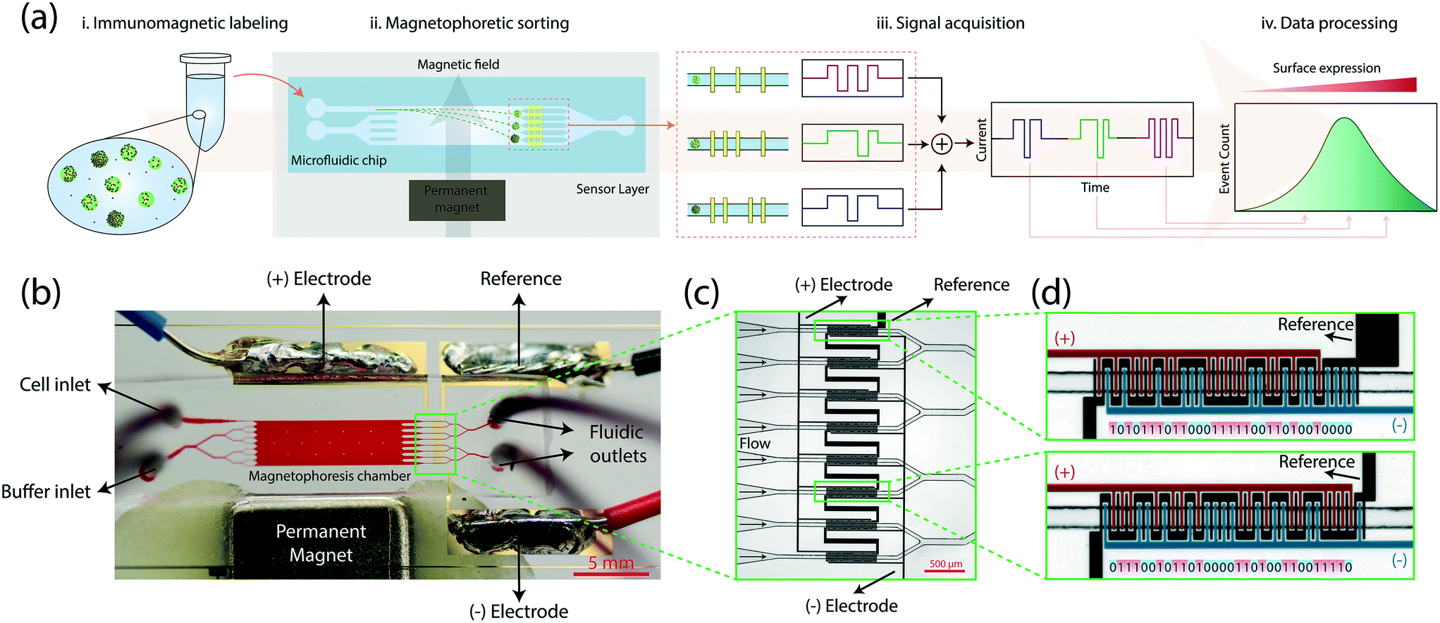 | ||
| Fig. 1 Design and operation of the microfluidic system. (a) Summary of the process flow. (i.) Immunomagnetically labeled cells are introduced to the microfluidic device from a single inlet. (ii.) Sheath-flow focused cells deflect in the transverse axis based on their magnetic load under an external magnetic field as they traverse the microfluidic chip. (iii.) Cells sorted into different outlets generate digitally-coded electrical signals via a code-multiplexed Coulter counter array. (iv.) The electrical signal is decoded to quantify spatial distribution of cells and an expression histogram is produced via computational analysis of sensor signals. (b) A photo of the fabricated device filled with a colored dye for illustration. The sample is injected through the cell inlet. A buffer solution (1× PBS) is driven through the buffer inlet to create a sheath flow. The outward flow divides into 8 fluidic channels where each fluidic channel is accompanied by a Coulter sensor coded with a unique 31-bit digital sequence. The whole sensor network is created by micropatterning 3 electrodes, positive, negative and reference electrodes. The sensor is driven through the reference electrode, and the current signal from positive and negative electrodes are differentially measured to create a bipolar output signal. (c) A microscope image of the code-multiplexed Coulter sensor network aligned with the microfluidic bins. (d) A close-up image of the coded Coulter sensors. Sensors 1 and 6 are shown as examples to demonstrate their unique electrode patterns encoding distinct 31-bit digital codes. Each electrode finger of the positive electrode (highlighted in red) corresponds to a positive (“1”) bit. Similarly, a finger of the negative electrode (highlighted in blue) generates a negative (“0”) bit. | ||
Microfluidic components in combination with on-chip electrical detection allowed the whole cytometer to be built as a disposable platform that could fit on a standard 1 inch by 3 inch glass slide (Fig. 1b). Our device consisted of a polydimethylsiloxane (PDMS) microfluidic layer fabricated with soft lithography, on-chip electrical sensors created by patterning a 500 nm-thick gold film on the glass slide with a lift-off process, and a neodymium permanent magnet to generate a transverse magnetic field gradient along the microfluidic chamber (Methods). On the device, a sample inlet and a buffer inlet (bifurcated to provide a uniform sheath flow) led to a 1 cm-long, 3 mm-wide microfluidic chamber for magnetophoretic sorting of cells. To maintain a consistent magnetic field gradient in the microfluidic chamber, the spacing between the magnet and the microfluidic chamber was lithographically set during the fabrication process (Fig. S1,† Methods). Each cell exited from the sorting chamber into one of the eight microfluidic channels (i.e., microfluidic bins), precisely aligned with surface electrode patterns for electrical detection.
To detect cells in microfluidic bins, we used the Microfluidic CODES, a multiplexed biosensor technology for distributed Coulter detection on microfluidic chips.21 Compared to optical time-domain-encoding approaches,22,23 Microfluidic CODES's use of electrical signals simplifies the system design and integration. The whole sensor was made up of three sets of electrodes micropatterned to create a distinct electrode pattern at each of the eight microfluidic bins (Fig. 1c). As the sorted cells flowed over these patterned electrodes, they modulated the impedance between electrodes via Coulter principle and produced distinct electrical signals dictated by the underlying electrode pattern. We specifically designed the electrode patterns to produce 31-bit Gold sequences24–26 (Table S1†) which could mathematically be distinguished due to their orthogonality (Methods). For each microfluidic bin, the arrangement of the negative and positive electrode fingers determined the code sequence, while the common electrode was used to drive the sensor (Fig. 1d).
System testing using heterogeneous cell populations
To create a heterogeneous sample for device testing, we mixed MCF-7 and MDA-MB-231, two breast cancer cell lines with varying levels of EpCAM expression. Cells were pre-stained with membrane-permeable cytoplasmic dyes of different colors for optical identification of the cell type without interfering with the membrane antigen labeling (Methods). Microscopic analysis of the cell mixture following incubation with anti-EpCAM conjugated magnetic beads showed greater accumulation of magnetic beads on MCF-7 cells than MDA-MB-231 cells on average (Fig. 2a), a result that is consistent with the flow cytometry measurements of EpCAM expression of two cell lines (Fig. S2†).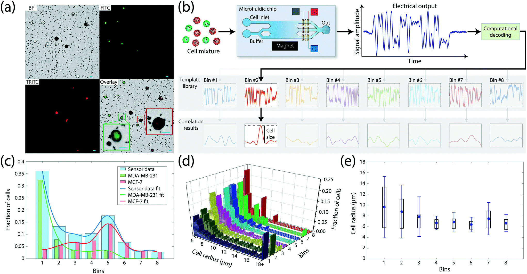 | ||
Fig. 2 Characterization of the microfluidic device using mixed cell populations. (a) Bright-field and fluorescent images of the immunomagnetically labeled cell mixture. MDA-MB-231 and MCF-7 breast cancer cell lines were pre-labeled with green and red fluorophores, respectively, for optical identification. MCF-7 cells have more anti-EpCAM conjugated magnetic beads attached to their surface due to higher EpCAM expression. Each scale bar represents 20 μm. (b) Decoding of the electrical signal to detect magnetophoretically sorted cells. Device output signal is compared to the code templates prepared for each possible microfluidic bin that can receive the sorted cell. The corresponding bin is identified when the comparison yields in a distinctive correlation peak among templates. The magnitude of the matching correlation peak is used to calculate the size of the detected cell. (c) A histogram showing the sorted distribution of 1![[thin space (1/6-em)]](https://www.rsc.org/images/entities/char_2009.gif) :1 mixture of MDA-MB-231 and MCF-7 cells to microfluidic bins. The total number of sorted cells in each bin is obtained electrically. The composition of the sorted population in each microfluidic bin was obtained through fluorescence microscopy. Two sub-histograms represent the fraction of each cell line (green for MDA-MB-231 and red for MCF-7) for each bin. (d) A histogram showing the identity of the microfluidic bin (i.e., the surface expression) and the cell size, all obtained by processing the output signal from the microfluidic device. (e) Size measurements of cells when gated by fluidic bins (increasing EpCAM expression from 1st bin towards 8th bin). MCF-7 cells have a smaller mean size and narrower spread in size than MDA-MB-231 cells. Dot denotes mean value, whisker denotes standard deviation, and box denotes 25th and 75th percentiles. :1 mixture of MDA-MB-231 and MCF-7 cells to microfluidic bins. The total number of sorted cells in each bin is obtained electrically. The composition of the sorted population in each microfluidic bin was obtained through fluorescence microscopy. Two sub-histograms represent the fraction of each cell line (green for MDA-MB-231 and red for MCF-7) for each bin. (d) A histogram showing the identity of the microfluidic bin (i.e., the surface expression) and the cell size, all obtained by processing the output signal from the microfluidic device. (e) Size measurements of cells when gated by fluidic bins (increasing EpCAM expression from 1st bin towards 8th bin). MCF-7 cells have a smaller mean size and narrower spread in size than MDA-MB-231 cells. Dot denotes mean value, whisker denotes standard deviation, and box denotes 25th and 75th percentiles. | ||
To test the device operation, we processed the mixture with an analytical version of the device, which allowed for the collection of sorted cells from individual bins for microscopic analysis (Fig. S3†), recorded the electrical data and compared them with independently performed optical measurements on the sample (Methods). The output signal was processed by custom-built software which identified the microfluidic bin a cell was sorted into by cross-correlating the signal with a computer-generated template library (Methods). Due to the orthogonality of bin waveforms, signal from each cell produced a strong correlation peak for only one of the microfluidic bins (Fig. 2b), while occasional interference due to coincident cells were successfully resolved using a recursive decoding algorithm (Fig. S4†). The effect of free magnetic beads on the electrical data was negligible due to their significantly smaller size than cells. Electrical data from 1070 cells processed on the device produced a magnetic cell sorting histogram with two peaks, centered at bins #1 and #5 corresponding to low and high EpCAM expression, respectively (Fig. 2c). Correspondence of these peaks to two different cell types was subsequently confirmed by fluorescence microscopy of cell populations collected from individual bins (Fig. S5†), which identified 89.75% of cells in bin #1 as MDA-MB-231 cells and 81.25% of cells in bin #5 as MCF-7 cells. The observed heterogeneity at the bin level is expected due to a wide range of expression levels displayed even within the same cell line, which resulted in a certain amount of overlap between expression levels of MDA-MB-231 and MCF-7 cell populations (Fig. S2†). However, the gradual shift of the prevalence of low-expressor MDA-MB-231 cells in lower-numbered bins to high-expressor MCF-7 cells in higher-numbered bins demonstrated the correlation between the cell surface expression and the microfluidic bin number from electrical measurements.
In addition to the enumeration of sorted subpopulations, we used the electrical data to estimate the size of sorted cells utilizing the fact that the Coulter signal amplitude for a cell is proportional to its volume20 (Fig. 2d). For each cell, we recorded the peak template cross-correlation value as a measure for the signal amplitude and calculated the cell radius by setting the mean signal amplitude from the whole sample to match the average cell size obtained from microscopy analysis (Methods). When gated by the microfluidic bin (i.e., surface expression), size measurements showed MDA-MB-231 cells to be larger with greater size variation than MCF-7 cells (Fig. 2e), a result in agreement with flow cytometry analysis of the two cell populations (Fig. S6†). Measurements of abnormally large cell sizes were due to doublets or triplets (Fig. S7†) and demonstrated the potential of size measurement as an important gating parameter.
Calibration of microfluidic bins for quantitative expression measurements
To quantitatively estimate the amount of the magnetic load on a cell from the microfluidic bin that it was sorted into, we developed a model of magnetophoretic cell sorting on our device using computer simulations. First, we created a static magnetic model by simulating the magnetic flux density in the microfluidic chamber based on the manufacturer-provided specifications of the magnet and its positioning with respect to the microfluidic chamber (Fig. 3a). The resultant magnetic force on a labeled cell was then calculated from the gradient of the dot product of the magnetic flux density and the cell magnetic moment, which was estimated from the manufacturer-provided size and permeability of the magnetic beads (Methods). Besides greater deflection with increasing magnetic load, finite element analysis of cell dynamics under pressure-driven laminar flow identified the cell size to be another significant contributor to the cell trajectory, with larger cells having less mobility under the same magnetic load due to higher Stokes drag forces (Fig. 3b). Therefore, we varied both the cell size and the number of magnetic beads and calculated the outlet deflection of cells from simulated trajectories to construct a comprehensive device model that linked the cell properties to a specific microfluidic bin for a given sample flow rate (Fig. 3c).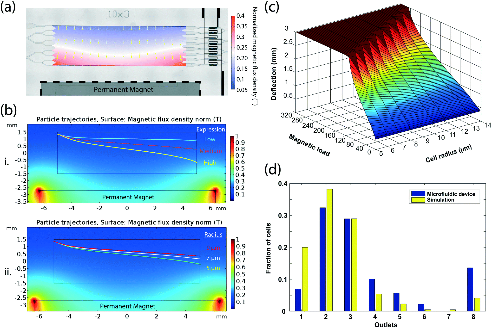 | ||
| Fig. 3 Calibration of microfluidic bins for quantitative expression measurements. (a) Simulated magnetic field due to external magnet inside the microfluidic device. Magnetic field amplitude plot is overlaid onto the microscopy image of the device. The direction and the length of arrows show the direction and the magnitude of the magnetic field gradient. (b) Simulated magnetic particle flow trajectories via finite element analysis. Panel (i) shows the trajectories of a low (10 beads), a medium (50 beads), and a high (100 beads) expressor cell of the same size (r = 8 μm). Panel (ii) shows the deflection of cells with the same expression but with 9 μm, 7 μm, and 5 μm radii. Larger cells face a larger drag force in the transverse axis, thus deflect less than smaller cells. (c) A plot showing the simulated deflection of an immunomagnetically labeled cell on the microfluidic device as a function of the number of magnetic beads attached and its size. The flat region corresponding to >3 mm deflection in the plot represents the saturation of the sensor as cells that would have deflected more are still captured in the furthest (eight). The plot is used as a look-up table for calculating the cell magnetic load. (d) Comparison of the simulated and experimental distribution of a SK-BR-3 cell population sorted on the microfluidic device. For computer simulations, the number of magnetic beads and the cell size were obtained through microscopic analysis of the cell population. Based on these measurements the cell deflection and the receiving microfluidic bin were determined using the look-up table in (c). | ||
To test the validity of our model, we compared theoretical predictions with experimental results from the processing of an independently-characterized cell population on our device. After processing 632 immunomagnetically labeled SK-BR-3 cells on our device at 30 mbar, we imaged those cells using a microscope (Fig. S8†) and measured cell size and the number of surface-bound beads with custom-built image processing software (Methods). The distribution of the optically-characterized cell population in eight microfluidic bins predicted by the computer model was comparable (correlation coefficient of 0.9175) to the experimental observations from electrical recordings, considering the tendency of image-based analysis to underestimate the magnetic bead count on cells (Fig. 3d).
High dynamic range expression profiling via flow rate modulation
While the detection of differentially sorted cells in discrete microfluidic bins enables robust discrimination between subpopulations, it limits the dynamic range of surface expression measurements. To enhance the dynamic range, we purposely modulated the flow rate during processing and cumulatively analyzed the sample response. With this approach, different flow rates varied the cell residence time in the microfluidic chamber, and therefore microfluidic bins were dynamically tuned to discriminate cells at different ranges of magnetic load (Fig. 4a), effectively increasing the dynamic range of surface expression that can be analyzed.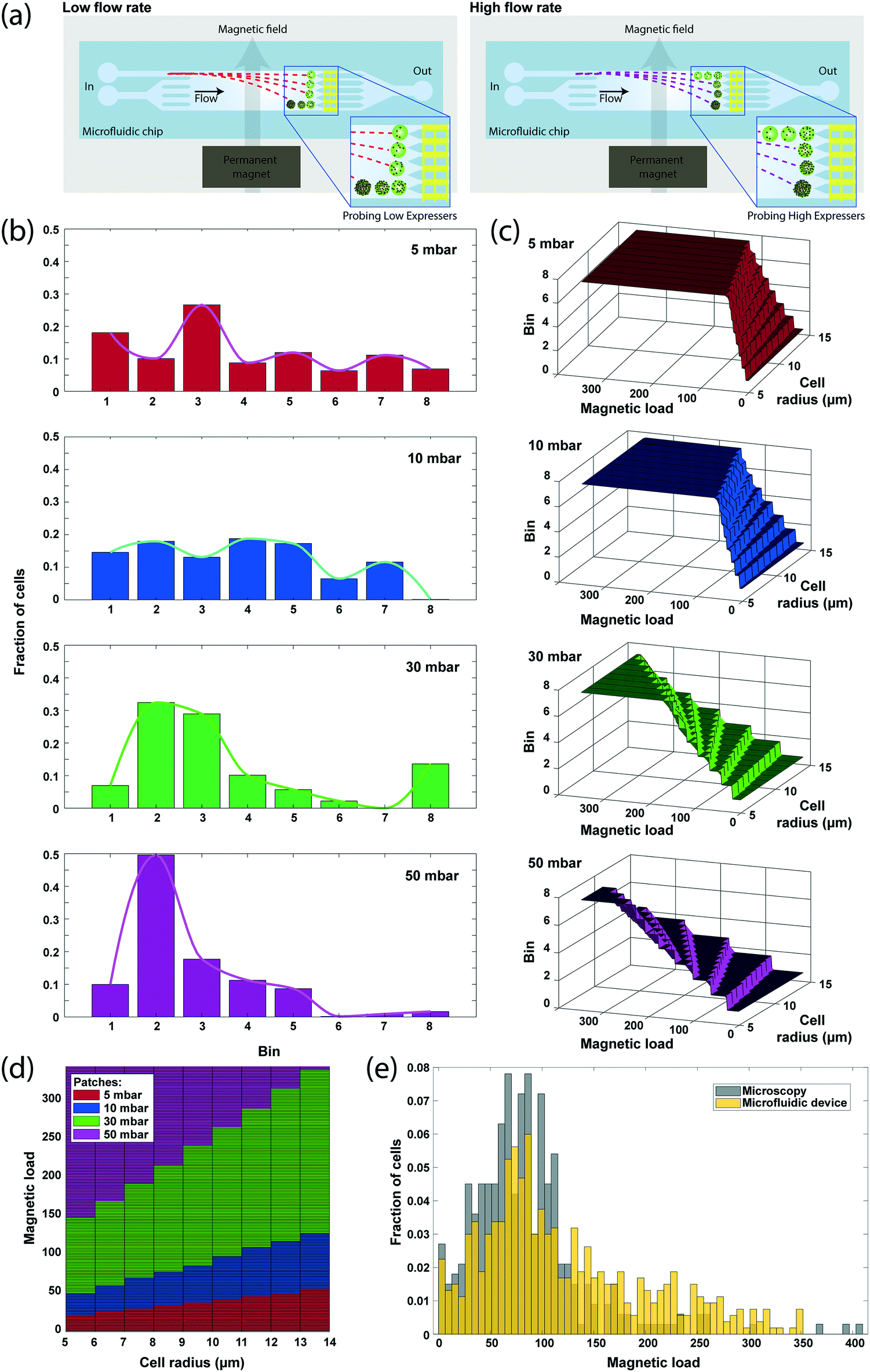 | ||
| Fig. 4 High dynamic range surface expression profiling via sample flow rate modulation. (a) Cell residence time in the microfluidic chamber is tuned by varying the sample flow rate in order to probe different ranges of magnetic load. (b) Distribution of SK-BR-3 breast cancer cells sorted to different microfluidic bins obtained under different flow rates. As the flow rate increases, cells spend less time in the magnetic field and are directed into a bin closer than the one that they would have been sorted into otherwise. (c) Simulated microfluidic bin calibration curves for different flow rates. At low flow rates, low expressor cells can be discriminated by sorting them into different bins, whereas higher flow rates discriminate over a wider range of expression levels. The flat part in each plot represents the saturation of the sensor at that flow rate. (d) The high-dynamic range look-up table constructed from the aggregate simulation results for different flow rates. Optimum flow rate for cell expression analysis is color-coded for each locus. Boundaries between different loci are determined by the saturation limit of the sensor at lower flow rate. (e) Comparison of magnetic load measured by microscopy and the microfluidic device. By modulating the flow rate during sample processing, a higher dynamic range can be achieved from the device that would otherwise provide a 3-bit (8 bins) dynamic range. | ||
We processed 2292 immunomagnetically labeled SK-BR-3 breast cancer cells suspended at a concentration of ∼106 cells per ml while varying the sample drive pressure between 5, 10, 30 and 50 mbar by a software-controlled pressure regulator (Methods). The whole analysis, including the time for signal processing, took ∼4 minutes, yielding an effective throughput of >500 cells per min. Sensor data demonstrated a gradual shifting of cell populations from being sorted into distant microfluidic bins to ones closer to the inlet as the flow rate increased, and eventually reaching to an unsaturated state (at 50 mbar), where most cells were collected in the five microfluidic bins closest to the inlet (Fig. 4b). At low flow rates (5 and 10 mbar), the sensor data significantly underrepresented the number of cells sorted into the most distant bin because the majority of the cells directed to that bin were magnetically trapped on the sidewalls of the microfluidic chamber under low shear forces. While of practical concern, magnetic trapping of high-expressor cells at low flow rates did not affect the data analysis as low flow rates were exclusively used to discriminate low-expressor cells.
To calculate the magnetic bead distribution over the cell population, we processed the aggregate sensor data through a look-up table, which was constructed by simulating cell magnetophoresis at different flow rates using the computational model of our device introduced above. The look-up table not only predicted the number of magnetic beads on a cell from (1) the microfluidic bin the cell was sorted into, (2) its measured size and (3) the drive pressure, but also revealed the parameter locus optimal for the estimation of magnetic bead counts for different expression levels (Fig. 4c). By considering exclusively the data from the flow rate that provides the highest resolution for a given magnetic load range, we constructed an expression histogram with the assumption that a representative subset (n > 500) of the sample was processed under each flow rate (Methods). The resultant magnetic load histogram was able to show single bead differences with an effective dynamic range of 50.88 dB, which is higher than that any of the flow rates could provide alone (Fig. 4d) and produced a distribution profile that closely matched (correlation coefficient of 0.8970) with the histogram of the number of magnetic beads obtained through microscope image processing (Fig. 4e).
Benchmarking against florescence-based surface expression profiling
To compare our measurements with fluorescence-based surface expression analysis, we measured the EpCAM expression in an SK-BR-3 cell population with a commercial flow cytometer (LSRFortessa, BD Biosciences). For a direct comparison, optical data from the flow cytometer is calibrated by fitting the fluorescence intensity and the forward scatter width (FSC-W) with the magnetic load and the cell size data from microscopy (Fig. 5a and b), respectively (Methods). Mapping the molecular-level fluorophore amount to number of microscale magnetic beads resulted in a nonlinear fit due to steric effects especially observed at high magnetic load27,28 (Fig. 5a), while the FSC-W data from the cytometer produced a linear fit with the microscopically measured cell size data as expected3 (Fig. 5b).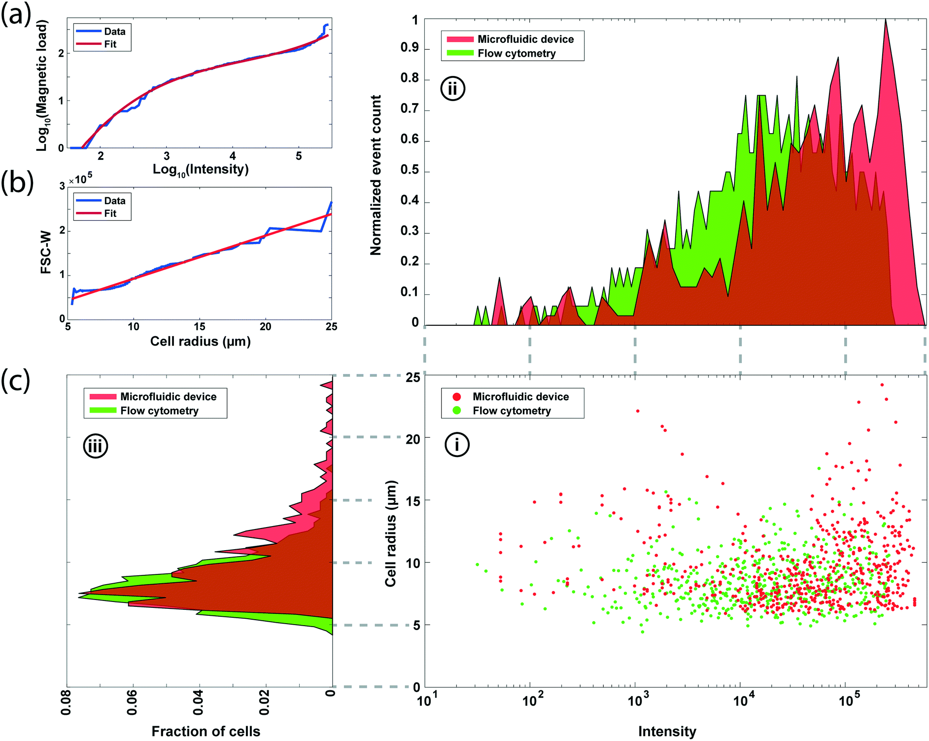 | ||
| Fig. 5 Benchmarking the microfluidic chip against florescence-based surface expression profiling. (a) Relation between number of magnetic beads measured via microscopy and the fluorescence expression data from the flow cytometer from analysis of SK-BR-3 cells. The least-squares regression fit is used for the conversion of fluorescence data to magnetic load for direct comparison. (b) The linear regression fit between the microscope-measured cell size and the forward scatter width (FSC-W) data from the flow cytometer for the same cell population in (a). (c) Comparison of the experimental results from the microfluidic device and flow cytometry. (i) The scatter plots of cell size vs. surface expression from 542 SK-BR-3 cells. (ii) Histogram of the surface expression distribution normalized to the event counts. (iii) Histogram of the size distribution. | ||
We processed matched samples of SK-BR-3 cells with our device and the commercial flow cytometer and compared the results for the EpCAM expression (Fig. 5c). From the analysis of 2292 cells on the microfluidic device, we obtained an HDR magnetic load distribution with a mean and standard deviation of 124.1 beads and 79.3 beads, respectively. In contrast, calibrated fluorescence measurements estimated a lower magnetic load with an average of 84.3 beads and a standard deviation of 49.7 beads. The mismatch between the two measurements is mainly due to the underestimation of the total number of magnetic beads (mean bead count is 90.2) on cells with brightfield microscopy, which was used to calibrate the fluorescence data. Otherwise, the two distributions match closely with coefficients of variation of 0.64 and 0.59 for the microfluidic device and commercial flow cytometer, respectively. As for the cell size measurement, our results show a 9.85 μm mean radius and 3.28 μm for standard deviation and match with the flow cytometry data of 8.45 μm mean radius and 2.11 μm for standard deviation.
Discussion
We introduce a microflow cytometry technique that combines magnetophoretic cell sorting with distributed Coulter detection to measure the surface expression of an antigen in a cell population. Unlike a conventional cytometer, where antigen expression is measured optically, our technique transduces the surface expression of a cell into a location on the microfluidic chip and uses coded surface electrodes to detect this location to complete the measurement. This projectile-based cytometry technique (which uses a microfluidic chip as a cell dispersing element) operates similar to a mass spectrometer because it takes the burden of sample discrimination off the sensor, making it possible to choose an optimal sensing modality for system integration and data acquisition instead of a specialized sensing modality.29 Moreover, encoding locations on a chip with electrode patterns achieves multiplexing of detection signals, allowing full data to be acquired from a single electrical waveform. These developments pave the way for an integrated yet disposable electrical flow cytometer which works as simple as a Coulter counter while achieving the measurement of surface antigens or other biomarkers that otherwise could not directly be probed electrically.Our technique is based not only on the specific attachment of magnetic beads to target cell membrane antigens but also on the fact that the number of magnetic beads on a cell surface correlates with the expression of that antigen.27,28 Antibody conjugated magnetic beads are readily available for a wide range of antigens for magnetic activated cell sorting (MACS). MACS is a popular approach in high-throughput binary or N-ary separation of cell subpopulations from heterogeneous samples based on the expression of a single30–36 or multiple markers.37 While lacking the extensive multiplexed detection capabilities of fluorescence measurements, our approach to magnetically manipulate cells for measuring their surface expression offers the opportunity to embed the sample preparation step in the flow cytometer and potentially enable expression profiling directly from complex matrices such as blood. By coupling MACS with a distributed sensor array, our technique inherits the advantages of MACS while acquiring the quantitative data fluorescence-based flow cytometers can provide.
Considering vastly different antigen expression levels between cells, the dynamic range of a flow cytometer is a crucial operational parameter. In our measurements, the dynamic range is directly affected/ultimately limited by the size of the magnetic beads employed to label the cells as a single magnetic bead determines both (1) the smallest discernable magnetic moment between the two cells and (2) the number that can fit on the cell surface, effectively setting a limit on the maximum magnetic moment a high expressor cell can attain. While we chose micron-sized magnetic beads as a trade-off between the dynamic range and the cell magnetophoretic mobility, the dynamic range can easily be enhanced with smaller beads in an optimized microfluidic design with greater magnetic field gradient.
To fully utilize the dynamic range offered by immunomagnetic labeling in antigen expression measurements, our technique augments a purposely simple device with microfluidic cell manipulation and computational analysis capabilities. By sweeping the sample flow rate during measurements, we vary the cell exposure time to the magnetic force field, allowing us to probe different ranges of expression levels within the cell population. This approach is analogous to how a high dynamic range photo is compiled by digital cameras as multiple images shot under different exposures to the “light” field are computationally merged into a single frame. Similarly, we combine all cell sorting data obtained under different “force” exposures controlled by the flow rate to create an expression histogram and achieve a dynamic range substantially higher than the 3-bit dynamic range offered by sorting magnetically labeled cells into eight discrete bins alone. It should also be noted that flow rate in our device do not need to be precisely controlled as the actual rate can be independently measured with on-chip electrical sensors for surface expression calculations.
Dynamic range of our technique can also be enhanced by increasing the number of microfluidic bins along with the number of code-multiplexed electrical sensors monitoring them. While the electrical sensor network can easily be expanded by assigning distinct codes to new sensors, a larger sensor network would unavoidably lead to more cell coincidence associated signal interference that might introduce errors in data processing.26 From a practical point of view, this would eventually require a dilution of the sample to lower the cell concentration.
Cell membrane antigens are commonly used as diagnostic38–40 and prognostic41,42 biomarkers in medical applications and as therapeutic targets in drug delivery.43,44 Our technique allows electrical profiling of antigen expression in a sample using an integrated yet frugal platform that integrates sample manipulation into the cytometry process, opening a path for direct expression profiling from unprocessed samples. Ability to perform cytometry beyond centralized laboratories can truly impact biomedical testing at the point of care especially for diagnosis of infectious diseases in resource-limited settings.
Methods
Microfluidic chip design
The microfluidic chip was designed with two inlets, one sample inlet and one buffer inlet that bifurcates into eight 30 μm-wide channels for creating a sheath flow. The sample inlet and buffer channels lead to a 1 cm by 3 mm chamber supported by 13 uniformly-distributed pillars for magnetophoretic deflection of labeled cells. At the end of the chamber, the outward flow is divided into eight 30 μm-wide and uniformly-spaced discrete channels for spatial mapping of sorted subpopulations. These channels join after the sensing area, and the analyzed sample is discharged off the device from two outlets.Electrical sensor design
The digital codes used for multiplexing the electrical sensors were generated as described by Liu et al.26 in the form of 31-bit Gold sequences. The 5th order polynomials x5 + x3 + 1 and x5 + x3 + x2 + x + 1 were used to represent two linear-feedback shift-registers with the initial states of “10000”. A set of 33 Gold sequences was obtained by these polynomials, and 8 of them were chosen to be employed in the electrical sensors (Table S1†). These codes were implemented with only 3 electrodes: two (a positive and a negative) sensing electrodes and a reference electrode placed between all sensing electrodes for excitation. Positive and negative electrode fingers were distributed around the reference electrode in order to establish the desired code sequence. Each electrode finger is 5 μm-wide, 90 μm-long and is separated from another by a 5 μm gap.
Device fabrication
The fabricated device was composed of three parts: a microfluidic layer, a permanent magnet, and a glass substrate with sensor electrode pattern. The microfluidic layer was fabricated out of polydimethylsiloxane (PDMS) layer using soft-lithography. In this process, a 4 inch silicon wafer was coated with 35 μm-thick SU-8 photoresist (SU-8 2035, MicroChem) to create the mold. The microfluidic features were patterned on the photoresist using conventional photolithography. The mold wafer was then treated with trichloro(octyl)silane for 8 hours for effortless detachment of cured PDMS from the mold. PDMS prepolymer and crosslinker (Sylgard 184, Dow Corning) were mixed at a ratio of 10:1 and poured on the mold, degassed in a vacuum chamber, and then cured for four hours at 65 °C. Finally, cured PDMS was peeled off from the mold and diced into individual devices. The electrical sensor network was fabricated using a lift-off process. A 1 inch by 3 inch soda-lime glass slide was coated with 1.5 μm-thick negative photoresist (NR9-1500PY, Futurrex). The sensor electrode pattern was transferred onto the photoresist layer with a maskless aligner (Heidelberg MLA150) and subsequent developing of the exposed photoresist. A 500 nm-thick Cr/Au film stack was deposited onto the substrate using an e-beam evaporator (Denton Explorer). The micromachined glass substrate and the PDMS microfluidic layer were surface-activated in oxygen plasma, aligned under a microscope, and permanently bonded on a hot plate at 65 °C to create the microfluidic device. Next, a neodymium permanent magnet (B848, K&J Magnetics) was placed under the glass substrate and precisely aligned to the lithographically-defined alignment features within the PDMS layer under a microscope. Once aligned, the magnet was fixed in position using epoxy. The combined cost of materials and fabrication for the device (excluding the reusable magnet) was estimated to be <$4.5 per chip.
Cell cultures and reagents
MCF-7, SK-BR-3 and MDA-MB-231 breast cancer cells were purchased from the American Type Culture Collection (ATCC) and propagated according to the manufacturer's instructions. The cells were cultured in Dulbecco's modified Eagle's medium (DMEM) (Gibco) with 10% fetal bovine serum (Seradigm) and 1% penicillin/streptomycin (AMRESCO) in 5% CO2 atmosphere at 37 °C in an incubator. Once they reach 80% confluence, cells were detached from the culture flask using 0.25% trypsin–EDTA (Gibco) for 3 minutes. Subsequently, cells were pelleted, the supernatant was removed, and the cells were resuspended in 1× phosphate buffered saline (PBS) (Corning) solution for immunomagnetic labeling and other protocols.Fluorescent staining of cells
MCF-7 and MDA-MB-231 cells were stained with orange CMRA cell tracker (Invitrogen) and green CMDFA cell tracker (Invitrogen), respectively. 20 μg of the cell tracker was dissolved in dimethyl sulfoxide (DMSO) (Sigma-Aldrich) to the final concentration of 10 mM. The solution was then diluted to 5 μM by addition of serum-free DMEM media. The culture media was replaced with 4 mL of the prepared staining solution and cells were incubated in 5% CO2 atmosphere at 37 °C for 30 min. Following confirmation of successful labeling with a microscope, cells were washed with 1× PBS.Immunomagnetic labeling
For magnetic labeling of cells, 1 μm-diameter streptavidin-coated magnetic beads with (Dynabeads MyOne Streptavidin C1, Invitrogen) were used. First, 12 μL of stock bead solution (at a concentration of ∼7–10 × 109 beads per mL in phosphate buffered saline (PBS) at pH 7.4 with 0.01% Tween-20, and 0.09% sodium azide) was used to pellet and resuspend magnetic beads in 1× PBS. Then, magnetic beads were conjugated with 10 μL of monoclonal biotin-conjugated anti-EpCAM antibody (BioLegend, catalog #: 324216) at 4 °C for 15 min. Functionalized beads were pelleted using an external magnet and washed with 0.1% bovine serum albumin (BSA) and 1% Tween-20 solution to minimize non-specific binding. The sample was then mixed with antibody-conjugated beads at a ratio of 300 beads per cell and incubated on a rocker for 45 minutes at room temperature. The cost of the immunomagnetic labeling was estimated to be <$0.30 per 10000 cells.
Flow cytometry analysis
Quantitative fluorescent measurements of EpCAM expression on MCF-7, SK-BR-3 and MDA-MB-231 cells were performed with an LSRFortessa flow cytometer (BD Biosciences) for independent cell characterization for data validation and benchmarking of our technology. All three cell lines were labeled with phycoerythrin-conjugated EpCAM antibody from the same clone used in magnetic labeling (BioLegend, catalog #: 324205) by following the manufacturer's protocol. At least 3000 events were recorded for each analysis. The flow cytometry data were analyzed in FlowJo software (FlowJo, LLC) and exported to MATLAB (MathWorks) for further data analysis and visual representation.Sample processing
Prior to experiments, microfluidic devices were incubated with 0.1% BSA and 1% Tween-20 solution for 1 hour at 4 °C to minimize non-specific binding of cells to the device. This step was instrumental in preventing free magnetic beads in the sample from accumulating in the device and hindering the sample flow and magnetic manipulation of cells. During processing, the sample was loaded into a sealed 10 ml laboratory tube and was pneumatically driven through the device using a software-controlled pressure regulator (MFCS-EZ, Fluigent). For electrical measurements, the device was driven by a 500 kHz sine wave, and the resulting signal amplitude was measured with a lock-in amplifier (HF2LI, Zurich Instruments). Briefly, electrical current signals from positive and negative sensing electrodes were first converted into voltage signals using transimpedance amplifiers and were subtracted from each other using a differential amplifier. The amplitude of the differential signal was sampled from the output of the lock-in amplifier into a computer for further analysis. Acquisition and processing of the electrical signals were achieved by custom-built software developed with LabVIEW (National Instruments). At the end of each experiment, the device was disposed following the removal of the magnet.Electrical signal processing
The data from the microfluidic device were sampled at 500 kHz using a data acquisition board (PCIe-6361, National Instruments) and processed using custom-built software.21,45 The software was initially provided with the digital codes for all microfluidic bins and identified parts of the waveform that corresponded to individual sensor signals through correlation. By averaging a sufficient number (n > 10) of signals, a template library specific to the device and sample is created to accommodate device-to-device or sample-to-sample variations. Coincident cells (i.e., cells arriving concurrently to the same or different microfluidic bins) were resolved through successive interference cancellation (Fig. S4†). At the end of the decoding process, the software output the microfluidic bin identity and the size information corresponding to each cell sorted on the microfluidic device.Visual investigation of device operation
High-speed microscope images of sorted cells were recorded to validate the operation of magnetophoresis stage and the sensor network. Cells were imaged as they were processed on the chip using a high-speed camera (Vision Research Phantom v7.3) attached to an inverted microscope (Nikon Eclipse Ti). The data were used to optimize the sample flow speed and to validate the operation of the sensor network by comparing the electrical signals with the matching images of cells sorted into different microfluidic bins.Microscopic measurement of cell magnetic load
Brightfield images of 500 immunomagnetically labeled cells were acquired with a microscope and investigated using a custom image processing program in MATLAB for each sample. Individual cells in the microscopy images from the monochrome camera were first windowed into 200 pixels by 200 pixels images and those images were imported into MATLAB. Histogram equalization was applied to eliminate the brightness and contrast deviation between the images. Next, a threshold was set to robustly discriminate the magnetic beads and suppress the background containing other features of the cells such as its membrane. In those images, the number of dark pixels was counted to calculate the area covered by the magnetic beads on a cell surface. Next, the same process was also applied to the images of free single beads to calculate the mean number of pixels per bead. Then, the number of magnetic beads on a cell was determined by dividing the total number of dark pixels in an image of a cell by the mean number of pixels per bead. While this technique provided accurate results for low expressors, it underestimated the magnetic load for high expressors due to the 2-dimensional projection of 3-dimensional objects on the image plane and the overlapping of the magnetic beads attached to opposite faces of a cell.Fluorescence characterization of sorted cell populations
An analytical version of the microfluidic device that permits collection of sorted cell populations from eight dedicated outlets was designed and fabricated (Fig. S3†). Samples from eight outlets were collected in different test tubes and for each sample a 15 μL solution was deposited onto a glass slide and a coverslip was carefully placed. Each glass slide was scanned using a fluorescence microscope in FITC and TRITC fluorescence channels to identify different cell types. The number of cells in each fluorescent channel was obtained by the “Automated Measurement” function of the Nikon NIS Elements AR software.Finite element analysis
Magnetic and hydrodynamic operation of the microfluidic device was simulated by developing a finite element analysis model in COMSOL Multiphysics (COMSOL, Inc.). The model was constructed using “Magnetic Fields, No Currents (mfnc)”, “Laminar Flow (spf)” physics modules for magnetic and hydrodynamic aspects, respectively. To simulate the trajectories of cells with varying magnetic loads and flow rates, “Particle Tracing for Fluid Flow (fpt)” physics was employed. In these simulations, magnetic properties of the permanent magnet were implemented according to the manufacturer-provided specifications (K&J Magnetics). Similarly, the properties of the magnetic beads were obtained from the manufacturer and the study conducted by Tarn et al.46 In simulations, immunomagnetically-labeled cells were modeled as homogeneous particles with effective magnetic permeability, which is calculated based on the fraction of total volume of beads on the cell to the cell volume.Construction of the look-up table
Device operation was simulated by sweeping the cell size, magnetic load and sample flow using finite element analysis model explained above. Results from individual simulations were gathered into a single multidimensional matrix as a look-up table storing the magnetic load information using the cell size, flow rate and microfluidic bin identity as coordinates. For every cell event, the system refers to this matrix and performs the mapping to estimate a magnetic bead count.Conversion of the fluorescence expression data to magnetic load
Surface expression of cells in matched samples were analyzed using the developed microfluidic device and a commercial flow cytometer (LSRFortessa, BD Biosciences). Two datasets containing 500 events were sorted in ascending order as vectors and their base-10 logarithm were plotted. The resulting plot was analyzed in MATLAB using Curve Fitting Toolbox 3.5.7 to obtain a least squares regression fit. At the end of the analysis, a 3rd order polynomial fit (f(x) = p1 × x3 + p2 × x2 + p3 × x + p4) with calculated coefficients (p1 = 0.07558, p2 = −0.9428, p3 = 4.223, p4 = −4.86) was imported into MATLAB for the conversion of fluorescence expression data. A similar approach was taken for the microscopic cell size measurements and the forward scatter data from the commercial flow cytometer. The forward scatter width (FSC-W) was calibrated to the microscopic measurements via a linear fit in the form of f(x) = m1 × x + m2, where m1 = 9.988 ×10⁻⁵ and m2 = 0.9923.Conclusions
We introduced a flow cytometry technique that estimated the surface expression and size of an immunomagnetically labeled cell by electrically recording and computationally analyzing its magnetophoretic trajectory. Our approach allowed the whole flow cytometer to be realized as a disposable microfluidic platform that can directly be interfaced electronically. Furthermore, our analysis of EpCAM expression of human breast cancer cells validated our technique's accuracy by producing comparable results with a commercial fluorescence-based flow cytometer. We believe our magnetophoretic cytometry technique addresses several issues that currently limit the point-of-care adoption of conventional fluorescence-based flow cytometry by offering a chip-based, electronic alternative that is especially well suited for mobile and resource-limited scenarios.Author contributions
O. C. and A. F. S designed the research and wrote the manuscript. N. W. and R. L. designed the electronic sensor architecture. O. C., M. B. and R. L. fabricated microfluidic devices for experiments. O. C. and T. O. A. prepared the reagents and cell populations for experiments. O. C. conducted the experiments. O. C. and M. B. developed the finite element analysis model and performed computer simulations. N. W. developed the software for signal decoding and data analysis. O. C., N. W. and A. F. S. analyzed the data. All authors read and approved the final manuscript.Conflicts of interest
The authors declare no competing financial interests.Acknowledgements
This work was supported by National Science Foundation (NSF) Award No. ECCS 1610995 and ECCS 1752170, and Arnold and Mabel Beckman Foundation (Beckman Young Investigator Award to A. F. S.).References
- L. A. Kamentsky, M. R. Melamed and H. Derman, Science, 1965, 150, 630–631 CrossRef CAS PubMed.
- L. A. Kamentsky and M. R. Melamed, Science, 1967, 156, 1364–1365 CrossRef CAS PubMed.
- H. M. Shapiro, Practical Flow Cytometry, John Wiley & Sons, Hoboken, NJ, 4th edn, 2005 Search PubMed.
- K. D. Wittrup, Curr. Opin. Biotechnol., 2001, 12, 395–399 CrossRef CAS PubMed.
- V. M. Litwin and P. Marder, Flow Cytometry in Drug Discovery and Development, John Wiley & Sons, Hoboken, NJ, 2011 Search PubMed.
- P. O. Krutzik, J. M. Irish, G. P. Nolan and O. D. Perez, Clin. Immunol., 2004, 110, 206–221 CrossRef CAS PubMed.
- F. E. Craig and K. A. Foon, Blood, 2008, 111, 3941–3967 CrossRef CAS PubMed.
- D. Barnett, B. Walker, A. Landay and T. N. Denny, Nat. Rev. Microbiol., 2008, 6, S7–S15 CrossRef CAS PubMed.
- A. Alvarez-Barrientos, J. Arroyo, R. Canton, C. Nombela and M. Sanchez-Perez, Clin. Microbiol. Rev., 2000, 13, 167–195 CrossRef CAS PubMed.
- T. Horsburgh, S. Martin and A. J. Robson, Transplant Immunol., 2000, 8, 3–15 CrossRef CAS PubMed.
- F. S. Ligler and J. S. Kim, The Microflow Cytometer, Pan Stanford, Singapore, 2010 Search PubMed.
- D. S. Boyle, K. R. Hawkins, M. S. Steele, M. Singhal and X. Cheng, Trends Biotechnol., 2012, 30, 45–54 CrossRef CAS PubMed.
- M. Toner and D. Irimia, Annu. Rev. Biomed. Eng., 2005, 7, 77–103 CrossRef CAS PubMed.
- H. Zhu, S. Mavandadi, A. F. Coskun, O. Yaglidere and A. Ozcan, Anal. Chem., 2011, 83, 6641–6647 CrossRef CAS PubMed.
- P. Kiesel, M. Bassler, M. Beck and N. Johnson, Appl. Phys. Lett., 2009, 94, 041107 CrossRef.
- B. K. McKenna, A. A. Selim, F. Richard Bringhurst and D. J. Ehrlich, Lab Chip, 2009, 9, 305–310 RSC.
- B. K. McKenna, J. G. Evans, M. C. Cheung and D. J. Ehrlich, Nat. Methods, 2011, 8, 401–403 CrossRef CAS PubMed.
- S. Miltenyi, W. Muller, W. Weichel and A. Radbruch, Cytometry, 1990, 11, 231–238 CrossRef CAS PubMed.
- W. H. Coulter, Proc. Natl. Electron. Conf., 1956, 12, 1034 Search PubMed.
- R. W. Deblois and C. P. Bean, Rev. Sci. Instrum., 1970, 41, 909–916 CrossRef.
- R. Liu, N. Wang, F. Kamili and A. F. Sarioglu, Lab Chip, 2016, 16, 1350–1357 RSC.
- J. Martini, M. I. Recht, M. Huck, M. W. Bern, N. M. Johnson and P. Kiesel, Lab Chip, 2012, 12, 5057–5062 RSC.
- M. Muluneh, B. Kim, G. Buchsbaum and D. Issadore, Lab Chip, 2014, 14, 4638–4646 RSC.
- R. Gold, IEEE Trans. Inf. Theory, 1967, 13, 619–621 Search PubMed.
- R. Liu, W. Waheed, N. Wang, O. Civelekoglu, M. Boya, C. H. Chu and A. F. Sarioglu, Lab Chip, 2017, 17, 2650–2666 RSC.
- R. Liu, N. Wang, N. Asmare and A. F. Sarioglu, Biosens. Bioelectron., 2018, 120, 30–39 CrossRef CAS PubMed.
- K. E. McCloskey, J. J. Chalmers and M. Zborowski, Cytometry, 2000, 40, 307–315 CrossRef CAS PubMed.
- K. E. McCloskey, L. R. Moore, M. Hoyos, A. Rodriguez, J. J. Chalmers and M. Zborowski, Biotechnol. Prog., 2003, 19, 899–907 CrossRef CAS PubMed.
- D. Issadore, J. Chung, H. Shao, M. Liong, A. A. Ghazani, C. M. Castro, R. Weissleder and H. Lee, Sci. Transl. Med., 2012, 4, 141ra92 Search PubMed.
- E. Ozkumur, A. M. Shah, J. C. Ciciliano, B. L. Emmink, D. T. Miyamoto, E. Brachtel, M. Yu, P. Chen, B. Morgan, J. Trautwein, A. Kimura, S. Sengupta, S. L. Stott, N. M. Karabacak, T. A. Barber, J. R. Walsh, K. Smith, P. S. Spuhler, J. P. Sullivan, R. J. Lee, D. T. Ting, X. Luo, A. T. Shaw, A. Bardia, L. V. Sequist, D. N. Louis, S. Maheswaran, R. Kapur, D. A. Haber and M. Toner, Sci. Transl. Med., 2013, 5, 179ra47 Search PubMed.
- N. M. Karabacak, P. S. Spuhler, F. Fachin, E. J. Lim, V. Pai, E. Ozkumur, J. M. Martel, N. Kojic, K. Smith, P. Chen, J. Yang, H. Hwang, B. Morgan, J. Trautwein, T. A. Barber, S. L. Stott, S. Maheswaran, R. Kapur, D. A. Haber and M. Toner, Nat. Protoc., 2014, 9, 694–710 CrossRef CAS PubMed.
- J. J. Chalmers, M. Zborowski, L. P. Sun and L. Moore, Biotechnol. Prog., 1998, 14, 141–148 CrossRef CAS PubMed.
- N. Pamme and C. Wilhelm, Lab Chip, 2006, 6, 974–980 RSC.
- D. Robert, N. Pamme, H. Conjeaud, F. Gazeau, A. Iles and C. Wilhelm, Lab Chip, 2011, 11, 1902–1910 RSC.
- R. Jack, K. Hussain, D. Rodrigues, M. Zeinali, E. Azizi, M. Wicha, D. M. Simeone and S. Nagrath, Lab Chip, 2017, 17, 1349–1358 RSC.
- M. Poudineh, P. M. Aldridge, S. Ahmed, B. J. Green, L. Kermanshah, V. Nguyen, C. Tu, R. M. Mohamadi, R. K. Nam, A. Hansen, S. S. Sridhar, A. Finelli, N. E. Fleshner, A. M. Joshua, E. H. Sargent and S. O. Kelley, Nat. Nanotechnol., 2017, 12, 274–281 CrossRef CAS PubMed.
- J. D. Adams, U. Kim and H. T. Soh, Proc. Natl. Acad. Sci. U. S. A., 2008, 105, 18165–18170 CrossRef CAS PubMed.
- J. P. Sloane and M. G. Ormerod, Cancer, 1981, 47, 1786–1795 CrossRef CAS PubMed.
- G. S. Pinkus and P. J. Kurtin, Hum. Pathol., 1985, 16, 929–940 CrossRef CAS PubMed.
- L. Bevanger, J. A. Maeland and A. I. Naess, J. Clin. Microbiol., 1988, 26, 433–437 CAS.
- M. J. S. Wilkinson, A. Howell, M. Harris, J. Taylor-Papadimitriou, R. Swindell and R. A. Sellwood, Int. J. Cancer, 1984, 33, 299–304 CrossRef CAS PubMed.
- J. S. Ross, C. E. Sheehan, H. A. G. Fisher, R. P. Kaufman Jr, P. Kaur, K. Gray, I. Webb, G. S. Gray, R. Mosher and B. V. S. Kallakury, Clin. Cancer Res., 2003, 9, 6357–6362 CAS.
- T. M. Allen, Nat. Rev. Cancer, 2002, 2, 750–763 CrossRef CAS PubMed.
- A. M. Scott, J. D. Wolchok and L. J. Old, Nat. Rev. Cancer, 2012, 12, 278–287 CrossRef CAS PubMed.
- N. Wang, R. Liu and A. F. Sarioglu, J. Visualized Exp., 2017, 121, e55311 Search PubMed.
- M. D. Tarn, S. A. Peyman, D. Robert, A. Iles, C. Wilhelm and N. Pamme, J. Magn. Magn. Mater., 2009, 321, 4115–4122 CrossRef CAS.
Footnote |
| † Electronic supplementary information (ESI) available. See DOI: 10.1039/c9lc00297a |
| This journal is © The Royal Society of Chemistry 2019 |