
 Open Access Article
 This Open Access Article is licensed under a
 Creative Commons Attribution 3.0 Unported Licence
Quantitative analysis of gadolinium doped cerium oxide thin films via online-LASIL-ICP-OES
C.
Herzig
 a,
J.
Frank
b,
A. K.
Opitz
a,
J.
Fleig
a and
A.
Limbeck
*a
a,
J.
Frank
b,
A. K.
Opitz
a,
J.
Fleig
a and
A.
Limbeck
*a
aTU Wien, Institute of Chemical Technologies and Analytics, Getreidemarkt 9/164 I2AC, 1060 Vienna, Austria. E-mail: andreas.limbeck@tuwien.ac.at
bTU Wien, Joint Workshop, Technical Chemistry, Vienna, Austria
First published on 16th October 2019
Abstract
Laser ablation of solids in liquid (LASIL) coupled with ICP-OES detection was used as a new sampling technique for the analysis of ceramic thin films. The quantitative analysis of such thin films requires high sensitivity, due to a very low absolute analyte amount. For this purpose, the ablation cell, which is a key element for online coupling of the particle generation and detection system, was improved and the washout times could be reduced by a factor of 6 compared to previous publications. To demonstrate the capabilities of this online-LASIL technique, the elemental compositions of gadolinium doped cerium oxide (GDC) thin films were determined and energy dispersive X-ray microanalysis (SEM-EDX) was used as a reference technique. The film thickness of the investigated samples ranged from 220 nm to 14 nm. While SEM-EDX comes to its limits for films below 110 nm, online-LASIL-ICP-OES shows constant high accuracy and precision for all investigated films.
Introduction
Inorganic thin films based on metallic or ceramic materials already find widespread technological application as functional layers in optical, electronic or electrochemical devices1–3 or as passive layers to obtain special surface properties or improved tribological behaviour.4 Quantitative elemental analysis of inorganic thin films in the nm range is a challenging task. Basically there are two main routes that can be followed: (i) transformation of the solid material into a liquid and subsequent analysis or (ii) the use of solid sampling techniques.5 In the following, the possible analysis techniques – without any claim to completeness – shall be mentioned: for elemental analysis of liquids, atomic absorption spectroscopy (AAS), inductively coupled plasma-optical emission spectroscopy (ICP-OES), and inductively coupled plasma-mass spectrometry (ICP-MS) are widely used techniques with excellent precision and accuracy. In the field of solid sampling there is a great variety of techniques starting with X-ray based methods, such as X-ray photo electron spectroscopy (XPS) and energy dispersive X-ray microanalysis (SEM-EDX), leading to secondary ion mass spectrometry (SIMS), glow discharge-mass spectrometry (GD-MS), and laser ablation inductively coupled plasma-mass spectrometry (LA-ICP-MS).6 Solid sampling techniques usually provide the great advantage of enabling laterally resolved information and depth profiles, whereas quantification of the obtained data can be challenging. Due to matrix effects, matrix matched standards are necessary. For novel materials, these standards are not commercially available and in-house prepared standards are laborious in production and characterisation. In contrary, quantification of liquid samples can be easily achieved with commercially available certified reference materials. These liquid standards can be mixed in any ratio to fit the composition of the sample perfectly. For liquid sampling techniques on the other hand, transformation of the solid sample into a clear liquid can be challenging. Hazardous acids (e.g. hydrofluoric acid), additional equipment (e.g. microwave digestion system) and additional chemicals for fusion (lithium or sodium borate) can be necessary for sample preparation.7,8 These sample pre-treatment steps are time consuming and prone to introduce contaminations. Moreover, sample digestion is usually performed manually resulting in decreased reproducibility.As explained above, both approaches – (i) transformation of solid materials into liquid and (ii) solid sampling techniques – exhibit some drawbacks. To circumvent these drawbacks, a new solid sampling technique was proposed by Muravitskaya et al. in 2009.9 The basic concept of this technique, named laser ablation of solids in liquid (LASIL), is to produce nanoparticles of a solid sample by laser ablation while the sample is submerged in a liquid. The idea of placing solid samples in liquids and focussing a laser beam onto the sample surfaces can be traced back to Neddersen et al. in 1993,10 who aimed at the production of gold nanoparticles for investigation of surface enhanced Raman spectroscopy.11 Since then, LASIL has been mainly used for the synthesis of nanomaterials and nanostructures.12,13 But instead of using these nanoparticles solely for their enhancement effect in Raman spectroscopy, the particles themselves could be analysed and give information about the material they were made of.
The nanoparticle suspension obtained by LASIL can be introduced into the detection system (e.g. ICP-OES or ICP-MS) via a conventional liquid sample introduction system. The materials investigated with this technique so far were either metals,9 glasses (such as NIST 610/611)14,15 or SiC.16 All these approaches have in common that sample ablation and measurement were performed in two separate steps. Thus a manual handling step between the generation of the nanoparticle suspension and subsequent analysis is necessary. This pipetting step, for example, lowers reproducibility, hampers ambitions towards automatization of this technique and is a possible source of contamination and errors.
To overcome these drawbacks, we recently proposed an online-LASIL technique,17 where the particle suspension is directly introduced into the detection system without any further manual handling step. An in-house built ablation cell holds the sample and a constant stream of the carrier solution serves for transportation of the generated particles to the detection device. It could be shown that the online detection of iron doped strontium titanate nanoparticles is possible. However, for the quantitative analysis of thin films – especially in the low nm range – an increased sensitivity is necessary due to the small absolute analyte amount present.
To achieve this goal, an improved flow injection system and an advanced ablation cell design, ensuring fast washout and particle transport without any dispersion, was developed in the present work. To demonstrate the capabilities of this novel system, gadolinium doped cerium oxide (GDC) thin films ranging from 220 to 14 nm thickness are investigated and their composition is determined as precisely as possible.
Experimental
Instrumentation
A commercially available J200 Tandem LIBS instrument (Applied Spectra, Inc., Fremont, CA) equipped with a frequency quadrupled Nd:YAG laser (266 nm, 4 ns pulse duration) was used for laser ablation. For signal detection, a Thermo iCAP 6500 ICP-OES instrument (ThermoFisher Scientific, Bremen, Germany) equipped with an echelle optics and a charge injection device (CID) solid state detector was used. For further details on instrumentation and operating parameters see Table 1. A peristaltic pump (Perimax 12, SPETEC, Erding, Germany) was used to transport the carrier solution through the online-LASIL setup. For improved sample introduction efficiency, an aerosol desolventization system (APEX E, Elemental Scientific, Inc., Omaha, USA) equipped with a PFA nebuliser was used. Scanning electron microscopy (SEM, Quanta 200, FEI, USA) equipped with an energy dispersive X-ray spectrometer (EDX – Octane Pro Silicon Drift Detector, Ametek) was used to validate GDC results from online-LASIL experiments.| Laser ablation system | |
|---|---|
| Wavelength | 266 nm |
| Pulse duration | 4 ns |
| Repetition rate | 10 Hz |
| Laser fluence | 15 J cm−2 |
| Spot size | 100 μm |
| Sampling strategy | Line scan (300 μm s−1 scan speed); spot measurement (200 μm spot size, 19 J cm−2 laser fluence) |
| ICP-OES detection system | |
|---|---|
| Cool gas flow | 12 L min−1 |
| Auxiliary gas flow | 1.0 L min−1 |
| Nebuliser gas flow | 0.98 L min−1 |
| RF power | 1500 W |
| Viewing height | 14 mm |
| Integration time | 6 s |
| Emission lines [nm] | Ce 456.236, Ce 380.152, Ce 416.561, Gd 335.047, Gd 342.247, Gd 310.050, Y 371.030, Zr 339.198, Eu 412.970 |
Sample preparation
Gadolinium doped cerium oxide (GDC) thin films were prepared by pulsed laser deposition (PLD). A KrF excimer laser (248 nm wavelength, Lambda COMPexPro 201F) operated at a repetition rate of 5 Hz and 50 ns pulse duration was used to ablate the GDC target with approximately 1.5 J cm−2 laser fluence. Commercially available GDC powder (CeO2 doped with 20 at% Gd), purchased from Treibacher Industrie AG (Althofen, Austria), was pressed and sintered to be used as a target in the PLD process. As substrates, yttrium stabilised zirconium dioxide single crystals (YSZ, 9.5 mol% Y2O3) with 5 × 5 mm2 size and 0.5 mm thickness purchased from Crystec GmbH, Germany were used. During the PLD process, the substrates were heated to 600 °C to ensure crystalline film growth. Deposition times ranged from 16 min (4800 laser pulses in total) to 1 min (300 pulses in total). In each deposition process four 5 × 5 mm2 samples were produced simultaneously. The thickness of the prepared GDC films was determined on a sharp edge of the thin film with a profilometer (DektakXT, Bruker, Massachusetts, USA).Design of the LASIL cell
The basic concept of the ablation cell proposed in ref. 17 was adapted to increase usability and long term stability (see Fig. 1). Polyether-ether-ketone (PEEK), a chemical resistant and mechanically stable polymer, is now used as the body material instead of aluminium, enabling the use of diluted acids as the carrier solution. The main body contains two drillings for the inlet and outlet of the carrier solution (connected with polytetrafluoroethylene (PTFE) tubes) and a cavity to hold the sample. The cavity can house samples of 5 × 5 × 0.5 mm3. To obtain a channel with defined geometries, polydimethylsiloxane (PDMS) foil with 200 μm thickness is used (depicted in Fig. 1(b)). At the same time, this foil serves as a sealing between the PEEK body and the cover glass. UV grade fused silica (Crystran Ltd., Pool, UK) is used as a cover glass due to its high mechanical stability and transparency at 266 nm. The cover glass is mechanically fixed with a screwing mechanism. With these constructional improvements, samples can be exchanged within one minute.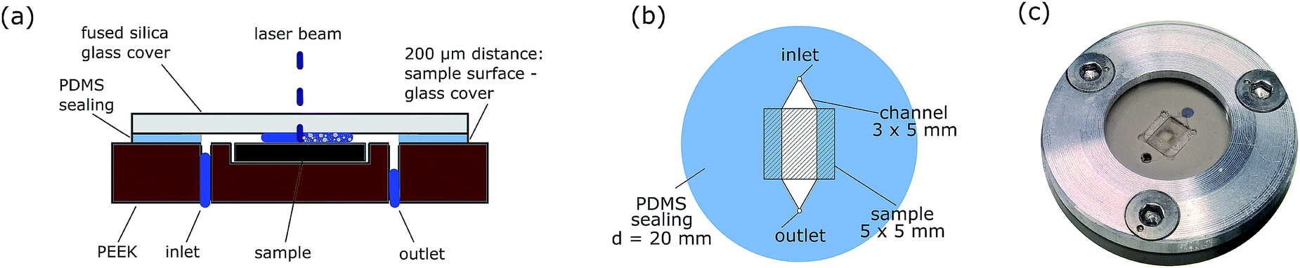 | ||
| Fig. 1 Cross section of the LASIL cell depicted with segmented flow of the carrier solution (a), PDMS foil used in the ablation cell for sealing and as the distance keeper providing different channel geometries (b) and optical image (c) of the assembled LASIL cell. | ||
These parts (cover glass, PDMS foil and sample surface) form a channel with 200 μm height. The channel can be as broad as the sample or give just access to a part of the sample instead by decreasing the width of the channel. Reducing the channel width and thus the accessible sample area increases the flow rate of the carrier solution over the sample surface, which is beneficial for better particle washout. For example with canal dimensions of 5 × 3 × 0.2 mm3 and 0.5 mL min−1 flow rate of the carrier solution, the liquid velocity is about 14 mm s−1 inside the channel.
LASIL measurements
For particle transport, diluted nitric acid (1% v/v) is used with Eu as an internal standard to correct instrumental drifts and to observe malfunction of the system. This carrier solution is prepared from concentrated nitric acid (65 mass%, EMSURE®), deionised water freshly prepared using a Barnstead™ Easypure™ II (18.2 M cm−1) and a Eu ICP-MS standard (Specpure®, Alfa Aesar, ThermoFisher, Kandel, Germany) with a resulting Eu concentration of 1 μg g−1. Segmented flow of the carrier solution, regularly interrupted by air bubbles, was created with a T-piece (Tee Asy Tefzel, 0.20 mm ID, IDEX Health & Science, LLC, Upchurch Scientific, Oak Harbor, WA) and two PVC tubes mounted on the peristaltic pump. One of the PVC tubes transports the carrier solution and the other one, ambient air. The carrier solution flow rate was set to 0.5 mL min−1. The ratio between the liquid and air bubble was roughly 3/1.The loaded LASIL cell was placed on the sample stage of the J200 instrument and line measurements were applied with the laser parameters given in Table 1. The as-produced nanoparticles were continuously transported by the carrier solution to the ICP-OES system. Derived emission signals were recorded and background corrected with instrument software (Qtegra, ThermoFisher Scientific, Bremen, Germany). The length of the measurement allowed 7 replicates per sample.
For external calibration, Ce (Specpure®, Alfa Aesar, ThermoFisher, Germany) and Gd ICP-MS standards (Certipur®, Merck, Germany) were mixed and diluted to achieve the sample composition and concentration. These standard solutions were flushed through the complete system including the ablation cell before (standard 1, lower concentration) and after (standard 2, higher concentration) sample ablation instead of the carrier solution. During the ablation of the sample, the system was rinsed with the carrier solution solely. For each analyte, three different emission lines were monitored to allow for the observation of any influence of spectral interferences originating from substrate elements. The most intense lines showing no spectral interference for Ce (380.2 nm) and Gd (342.2 nm) were used for stoichiometry calculations.
Results and discussion
Demonstrating fast cell washout
In Fig. 2 the detected shape of a single ablation peak is presented. Ablation time for this experiment was as short as possible. Therefore 10 laser pulses @ 10 Hz resulting in 1 s ablation time were chosen. The transient signal of the particles produced in this ablation event was recorded with 1 s time resolution of the detection system. Due to the short dwell time used in this experiment, elements from the substrate (Y and Zr) with strong emission lines and high concentration were monitored instead of elements of the GDC thin film. The APEX E desolventization system was not used in this type of experiment due to its higher gas volume (400 mL) compared to a cyclonic spray chamber (40 mL), which would lead to increased washout times. For comparison of the washout behaviour of different development stages of the ablation cell, peak widths at 1% of the peak maximum (FW0.01) are determined. Bonta et al.17 reported peak widths for a previous cell design and equipment of 35.2 ± 0.3 s FW0.01. When using the new cell design and improved flow injection equipment, the washout time can be reduced to 14.7 ± 2.3 s FW0.01 (n = 3). A further reduction of particle dispersion can be achieved with the introduction of a segmented carrier flow. This step reduces the peak width finally down to 5.8 ± 1.0 s FW0.01 (n = 38). In Fig. 2 the contribution of the two stages of improvement is displayed. The air segments between the liquid plugs effectively prevents the dispersion of particles. The nanoparticles produced in one liquid plug are trapped and cannot remix with a subsequent liquid portion leading to less signal broadening. It has to be mentioned that the segmentation of the carrier solution has to be established before the liquid enters the ablation cell. If the segmentation is applied shortly after the ablation cell, the beneficial effect is lost. Obviously, the particle washout at the ablation cell has a bigger contribution to particle dispersion than the dispersion due to the transportation in the tube. For further improvement of the washout behaviour, the focus should be on the design of the ablation cell. All in all – the new set up and all improvements described above – the washout time could be reduced by a factor of 6 compared to the first results of an online-LASIL system published.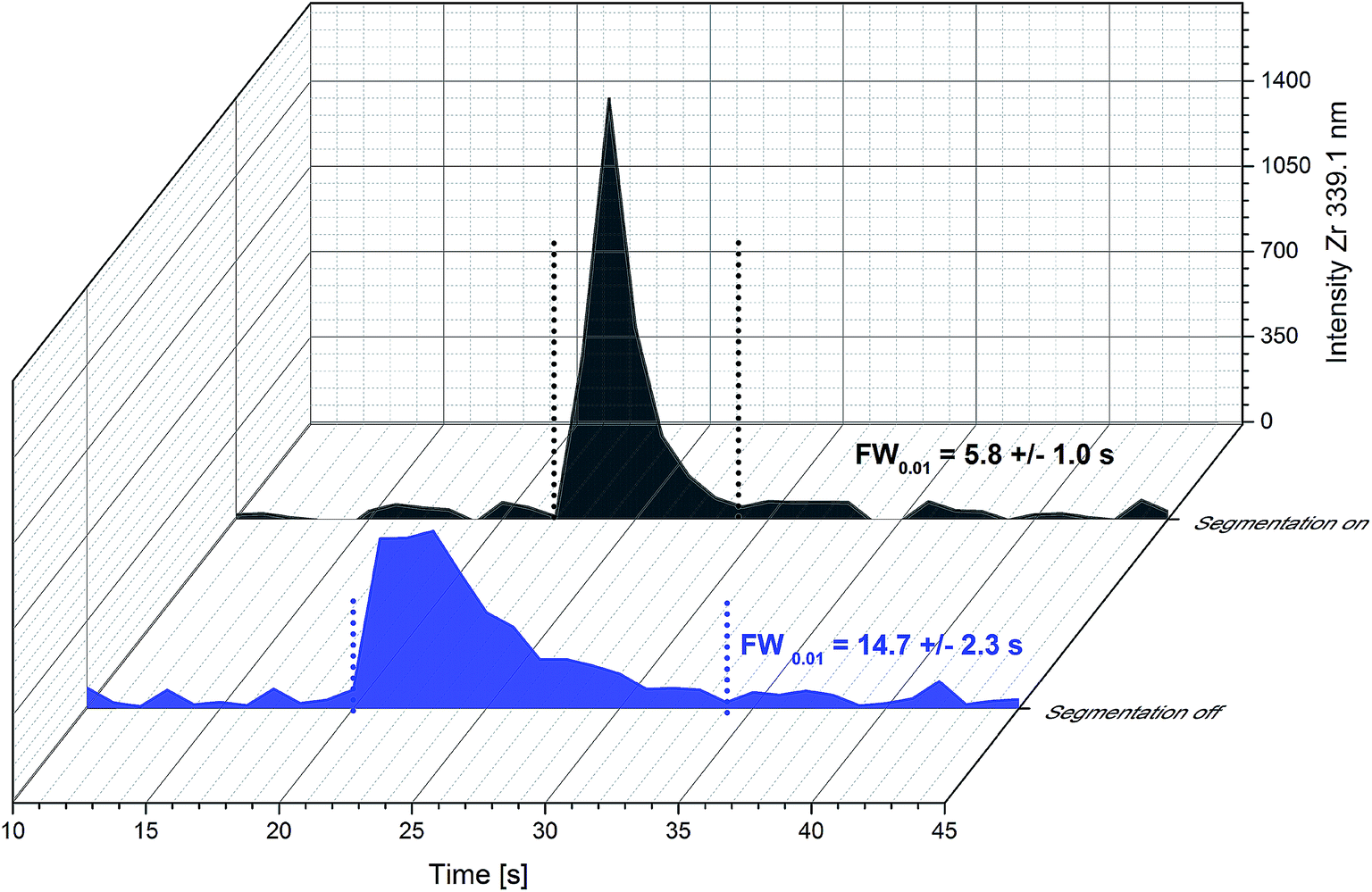 | ||
| Fig. 2 Influence of the segmentation of the carrier solution on peak profiles of single ablation events (10 laser pulses @ 10 Hz) obtained with the new ablation cell design. | ||
The demonstrated fast washout usually provides two benefits: (i) increased sensitivity because the same absolute amount of the analyte is more concentrated in a shorter period of time and (ii) spatially resolved analysis is possible. Long washout times cause unfeasibly long imaging times and lead to remixing of the analytes, which prevent correct correlation of the measured signals with lateral coordinates. For conventional LA-ICP-MS (particle transportation accomplished with He) there is still great effort to develop fast response ablation cells (see Van Malderen et al.18). Therefore the drastic reduction of the washout time of the online-LASIL setup can be regarded as a large step in the right direction.
Signal stability
Due to a slower sampling rate of ICP-OES compared to ICP-MS detection, long and stable signals are necessary for reproducible measurements. Therefore, line measurements with 10 Hz repetition rate of the laser pulses and other parameters given in Table 1 were performed to demonstrate long signal stability. With this repetition rate of the laser system, a steady state of the analyte concentration in the carrier solution could be achieved. In these experiments the APEX E desolventization system was used for signal enhancement. The signal dispersion due to the higher inner volume of such a device is in this case tolerable and even preferable, because of the smoothening of the signal to some degree. In Fig. 3, a typical signal plateau for the determination of the GDC thin film stoichiometry is depicted. The raw signal intensities show about 5% RSD in the steady state region between 60 and 110 s. For conventional liquid ICP-OES measurements 1–2% RSD can be expected. Slightly higher variances in the signal intensities obtained by online-LASIL can be seen. This can be explained by the segmented flow of the carrier solution. The presence or absence of the carrier solution has some effect on the ablation behaviour of the laser beam. Therefore the amount of material ablated per shot differs, but the composition is the same. This can be proved by looking at the intensity ratios of two emission lines measured for Ce and Gd in Fig. 3. The RSD of the intensity ratio in the steady state region drops to 0.4% and thereby allows very precise measurements when quantification is also accomplished via ratios.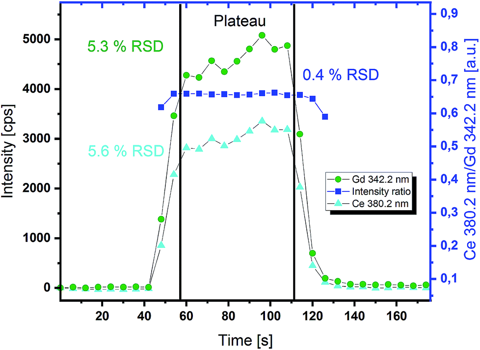 | ||
| Fig. 3 Transient signal of an online-LASIL-ICP-OES measurement of a GDC thin film (ablation performed while using a segmented carrier flow); continuous ablation for 60 s produces a steady state signal plateau used for stoichiometry determination. | ||
Signal quantification
Due to the easy availability and high flexibility of liquid standards (wide concentration range and adaptability to different samples), signal quantification with such a reference material is desirable. The results obtained with this calibration method are only valid if the standard (solution) and sample (nanoparticle suspension) exhibit a similar atomization-excitation efficiency in ICP. Ebdon et al.19 and Chen et al.20 have performed fundamental studies addressing this concern and reported that slurries with particles smaller than 2.5 μm (ref. 19) and 5 μm (ref. 20) respectively show the same behaviour as a liquid. Thus, no significant difference between the calibration standard and the sample is expected, since the average size of the particles produced in a LASIL experiment is reported to be smaller than 1 μm.16To demonstrate that such a nanoparticle suspension generated in the LASIL process exhibits the same properties as a liquid, raw intensities of the internal standard (Eu) of liquid calibration solutions and the nanoparticle suspensions were compared. At first, the relative standard deviation of the Eu signal of an extended set of measurements (n = 56) is 2.6% indicating a low variance between standards and samples. To verify this result, the non-parametric Wilcoxon signed-rank test for matched pairs is used. The Eu intensities of the bracketing standards and the samples are tested for significant differences. With a level of significance of 95%, there is no reason to claim that the intensities of these pairs are different (Wtest = 258, Wcritical = 91, 95% level of significance). This result confirms the assumption that a nanoparticle suspension produced in the LASIL measurement can be quantified with liquid standard solutions.
Application example: GDC thin films
To demonstrate the capabilities of the optimized system, stoichiometry of GDC thin films was determined. This material is an oxide ceramic with high oxide ion conductivity at enhanced temperatures and therefore used for example as the electrolyte material in solid oxide fuel cells (SOFC).21 PLD-grown GDC thin films with 5 different film thicknesses ranging from 220 to 14 nm were analysed with online-LASIL-ICP-OES and SEM-EDX as a comparative technique.22For signal quantification two standards with a similar composition to the sample were prepared to use the bracketing method to increase accuracy. In bracketing mode, one standard is slightly below the sample concentration and the second one is slightly above the sample concentration (see Table 2). Depending on the film thickness, the absolute concentration of the standards had to be adjusted by dilution to fit the measured intensities of the ablated analytes. The concentration of the applied calibration standards ranged from 0.33 to 3.26 μg g−1 for Ce and 0.08 to 1.00 μg g−1 for Gd. As explained above, the use of intensity ratios further enhances the precision of the measurement. The ratio of the emission line of Ce 380.2 nm and Gd 342.2 nm was used for stoichiometry determination showing the lowest variations of all possible combinations. However, the other combinations gave similar results too, indicating the absence of spectral interferences in the emission lines chosen for evaluation.
| Element | Standard 1 | Sample | Standard 2 | ||
|---|---|---|---|---|---|
| Ce | 85 at% | 3.26–0.408 μg g−1 | 80 at% | 75 at% | 2.67–0.333 μg g−1 |
| Gd | 15 at% | 0.64–0.080 μg g−1 | 20 at% | 25 at% | 1.00–0.128 μg g−1 |
To assess the capability of the improved online-LASIL technique a comparative quantification of the GDC thin films was performed by SEM-EDX. The results of both measurements are summarized in Fig. 4 and Table 3. For 220 nm film thickness, there is no significant difference between the results obtained by SEM-EDX and online-LASIL and also the variances of the results are comparable. The nominal composition of the bulk material provided by the supplier is 80 at% Ce and 20 at% Gd, but both methods find a significant enrichment of Gd in the thin film of 22.2 at% Gd. This might be a result of the PLD preparation process, which does not necessarily retain the exact target composition.17
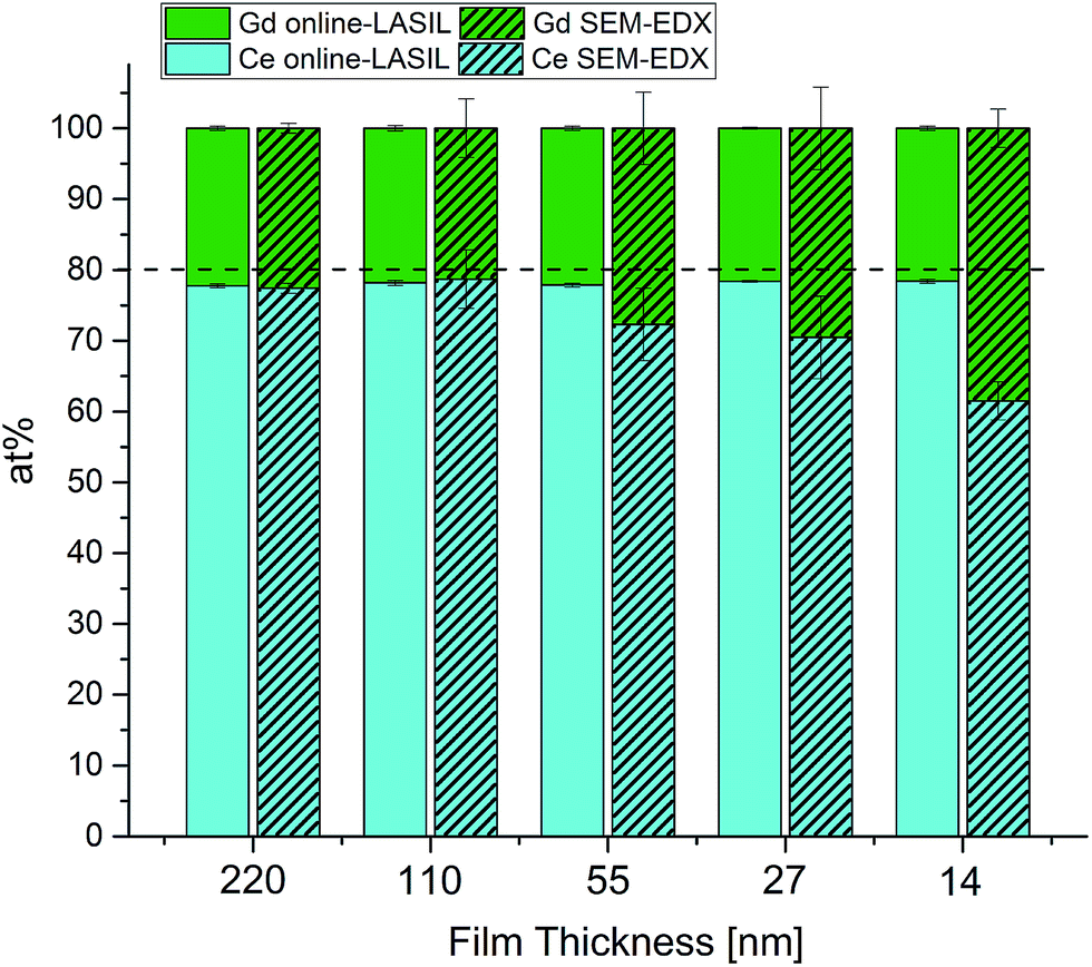 | ||
| Fig. 4 Comparison of stoichiometry results obtained by online-LASIL-ICP-OES and SEM-EDX measurements. | ||
| Film thickness [nm] | Online-LASIL-ICP-OES | SEM-EDX | ||
|---|---|---|---|---|
| Ce [at%] ± 1σ | Gd [at%] ± 1σ | Ce [at%] ± 1σ | Gd [at%] ± 1σ | |
| 220 | 77.8 ± 0.3 | 22.2 ± 0.3 | 77.4 ± 0.7 | 22.6 ± 0.7 |
| 110 | 78.2 ± 0.4 | 21.8 ± 0.4 | 78.7 ± 4.2 | 21.3 ± 4.2 |
| 55 | 77.9 ± 0.3 | 22.1 ± 0.3 | 72.3 ± 5.1 | 26.3 ± 5.5 |
| 28 | 78.4 ± 0.1 | 21.6 ± 0.1 | 70.5 ± 5.8 | 29.5 ± 5.8 |
| 14 | 78.4 ± 0.3 | 21.6 ± 0.3 | 61.5 ± 2.7 | 38.5 ± 2.7 |
As soon as the film thickness is reduced, SEM-EDX loses precision at first and accuracy subsequently. At 110 nm, average values of SEM-EDX are close to those found with online-LASIL ICP-OES but show about 10 times higher standard variation. For the thin films below 110 nm, stoichiometry cannot successfully be determined with SEM-EDX, whereas the online LASIL-ICP-OES system shows constant precision and accuracy even for thin films as low as 14 nm. Using a theoretical density ρth = 7.21 g cm−3 reported in ref. 23 and the total area ablated for one measurement (1.89 mm2), about 18 ng of GDC are used for one measurement demonstrating the high sensitivity of the improved LASIL procedure. For SEM-EDX, this analyte amount is too low to obtain reasonable results.
Estimation of film thickness
Although intensity ratios are used for stoichiometry determination, raw signal intensities show a good linear correlation with film thickness. Regression curves for the most intense emission lines of Ce (456.2 nm) and Gd (335.0 nm) are plotted in Fig. 5. The F-Value of ANOVA is above 1000 and indicates a highly significant model. The results obtained for samples with 110 nm film thickness tend to give higher intensities than expected. This deviation from the linear model might be explained by a slightly higher film thickness of the measured samples compared to the one used for determination of the film thickness. Nevertheless, it is possible to estimate the film thickness of an unknown sample astonishingly accurately with this regression curve, if measurement parameters are kept the same. For a better regression model, more equidistant calibration samples would be necessary.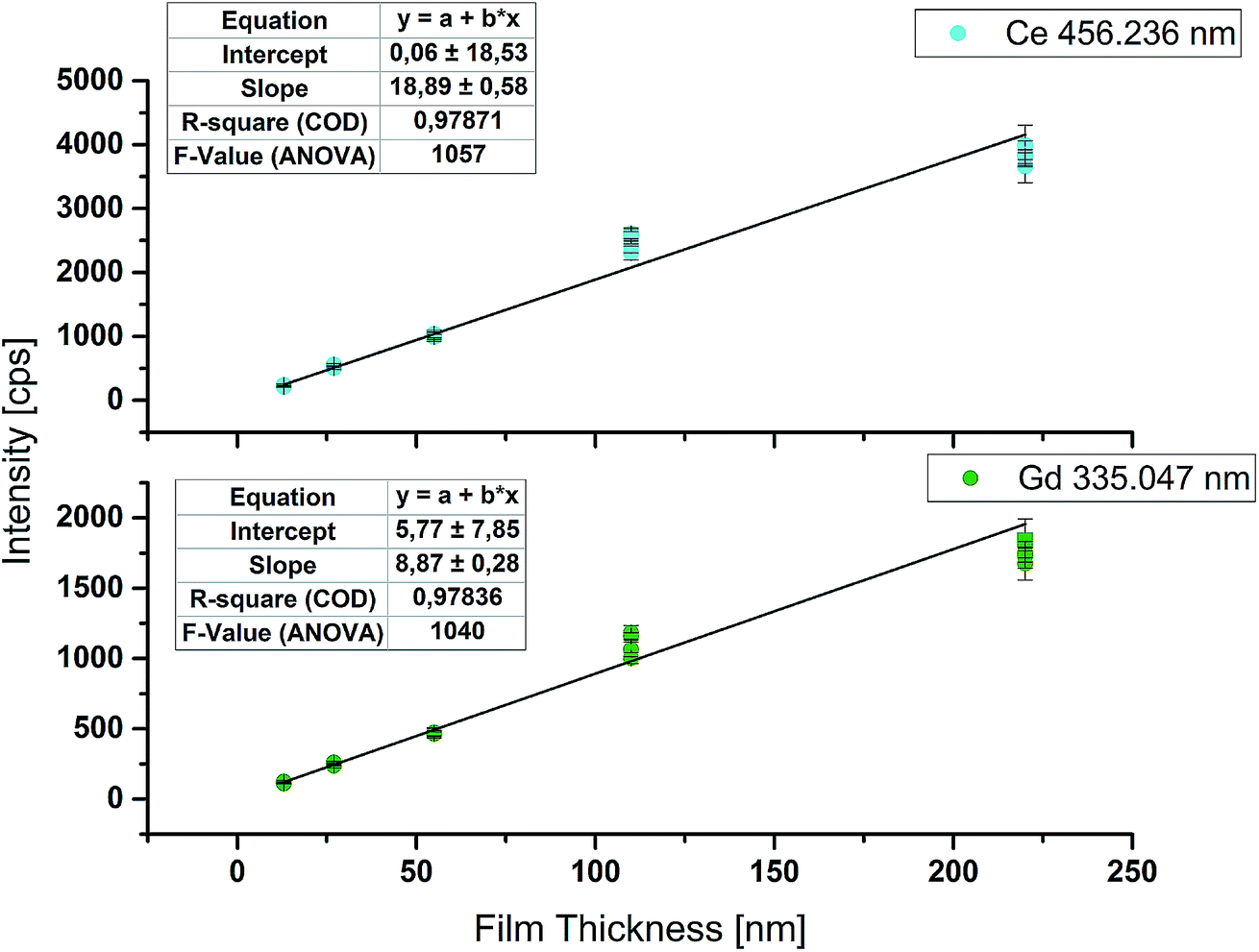 | ||
| Fig. 5 Correlation between raw intensities obtained by online-LASIL-ICP-OES and GDC film thickness. | ||
Furthermore, analogous to the limit of detection (LOD) of an analyte derived by measuring external calibration, it is possible to calculate the lowest detectable film thickness. Therefore the substrate material without the GDC thin film was ablated 10 times and used as the blank value. Calculation of the limit of detection was done according to DIN 32 645:2008-11. For Ce a LOD of 0.075 μg g−1 and for Gd a LOD of 0.015 μg g−1 were achieved. For both elements these values correspond to about 3 nm as the lowest detectable film thickness for the parameters used. According to Hernández et al.,24 GDC shows a F-centered cubic crystal structure with a lattice parameter a = 0.542 nm. Using this lattice parameter, about 6 monolayers of GDC can be successfully detected with the improved online-LASIL-ICP-OES setup presented in this work. Changing some measurement parameters, for example the scan speed, and thereby doubling the analyte amount in the carrier solution, could thus quite easily allow quantification of a few nm thick film.
Conclusion
In this work, online-LASIL-ICP-OES was used for the stoichiometry determination of GDC thin films. For this purpose, several goals had to be achieved to allow accurate and precise analysis of a small sample amount. Improvements of the design of the ablation cell and flow injection equipment and the segmentation of the carrier solution led to a drastic reduction of the washout time of ablated particles by a factor of 6. This reduction of the signal width at a simultaneously reduced flow rate of the carrier solution leads to better sensitivity of ICP-OES measurements. The accurate and precise stoichiometry determination of GDC thin films (220 to 14 nm) verified with SEM-EDX measurements shows the potential of this technique. Detection limits corresponding to 3 nm of film thickness could be achieved with this set of sampling parameters. If necessary, these parameters can be easily optimized with the focus on accurate determination of thin films in the few nm range. Online-LASIL can thus be seen as one of the answers to how to handle hard-to-dissolve materials, when precise quantification of small analyte amounts is necessary. Moreover, the reduced carrier flow rate enables the use of ICP-MS as a detection method in the future, providing enhanced sensitivity for most elements. Encouraged by the improvements of the washout time demonstrated here, depth profiling and imaging will be the next goals to be achieved.Conflicts of interest
There are no conflicts to declare.Acknowledgements
The authors gratefully thank the FWF Austrian Science Fund for supporting this project (P31165-N37).References
- Q. Lin, A. Armin, R. C. R. Nagiri, P. L. Burn and P. Meredith, Nat. Photonics, 2014, 9, 106 CrossRef.
- E. Fortunato, P. Barquinha and R. Martins, Adv. Mater., 2012, 24, 2945–2986 CrossRef CAS PubMed.
- C. Sun, R. Hui and J. Roller, J. Solid State Electrochem., 2010, 14, 1125–1144 CrossRef CAS.
- A. Kumar Sahoo and B. Sahoo, Measurement, 2013, 46, 2868–2884 CrossRef.
- A. Limbeck, M. Bonta and W. Nischkauer, J. Anal. At. Spectrom., 2017, 32, 212–232 RSC.
- G. Friedbacher and H. Bubert, Surface and Thin Film Analysis: A Compendium of Principles, Instrumentation, and Applications, Wiley, 2011 Search PubMed.
- M. Balcerzak, Anal. Sci., 2002, 18, 737–750 CrossRef CAS PubMed.
- J. Sneddon, C. Hardaway, K. K. Bobbadi and A. K. Reddy, Appl. Spectrosc. Rev., 2006, 41, 1–14 CrossRef CAS.
- E. V. Muravitskaya, V. A. Rosantsev, M. V. Belkov, E. A. Ershov-Pavlov and E. V. Klyachkovskaya, Spectrochim. Acta, Part B, 2009, 64, 119–125 CrossRef.
- J. Neddersen, G. Chumanov and T. M. Cotton, Appl. Spectrosc., 1993, 47, 1959–1964 CrossRef CAS.
- M. S. Sibbald, G. Chumanov and T. M. Cotton, J. Phys. Chem., 1996, 100, 4672–4678 CrossRef CAS.
- G. W. Yang, Prog. Mater. Sci., 2007, 52, 648–698 CrossRef CAS.
- Z. Yan and D. B. Chrisey, J. Photochem. Photobiol., C, 2012, 13, 204–223 CrossRef CAS.
- D. N. Douglas, J. L. Crisp, H. J. Reid and B. L. Sharp, J. Anal. At. Spectrom., 2011, 26, 1294–1301 RSC.
- S. Okabayashi, T. D. Yokoyama, Y. Kon, S. Yamamoto, T. Yokoyama and T. Hirata, J. Anal. At. Spectrom., 2011, 26, 1393–1400 RSC.
- R. Machida, R. Nishioka, M. Fujiwara and N. Furuta, Anal. Sci., 2017, 33, 537–544 CrossRef CAS PubMed.
- M. Bonta, J. Frank, S. Taibl, J. Fleig and A. Limbeck, Anal. Chim. Acta, 2018, 1000, 93–99 CrossRef CAS PubMed.
- S. J. M. Van Malderen, A. J. Managh, B. L. Sharp and F. Vanhaecke, J. Anal. At. Spectrom., 2016, 31, 423–439 RSC.
- L. Ebdon, M. E. Foulkes and S. Hill, J. Anal. At. Spectrom., 1990, 5, 67–73 RSC.
- C. Chen and T. W. McCreary, Appl. Spectrosc., 1994, 48, 410–412 CrossRef CAS.
- N. Mahato, A. Banerjee, A. Gupta, S. Omar and K. Balani, Prog. Mater. Sci., 2015, 72, 141–337 CrossRef CAS.
- J. L. M. Rupp, T. Drobek, A. Rossi and L. J. Gauckler, Chem. Mater., 2007, 19, 1134–1142 CrossRef CAS.
- R. O. Fuentes and R. T. Baker, Int. J. Hydrogen Energy, 2008, 33, 3480–3484 CrossRef CAS.
- W. Y. Hernández, O. H. Laguna, M. A. Centeno and J. A. Odriozola, J. Solid State Chem., 2011, 184, 3014–3020 CrossRef.
| This journal is © The Royal Society of Chemistry 2019 |