
 Open Access Article
 This Open Access Article is licensed under a
 Creative Commons Attribution 3.0 Unported Licence
Tailor-made biofuel 2-butyltetrahydrofuran from the continuous flow hydrogenation and deoxygenation of furfuralacetone†
Marc
Strohmann
a,
Alexis
Bordet
a,
Andreas J.
Vorholt
 *a and
Walter
Leitner
*ab
*a and
Walter
Leitner
*ab
aMax-Planck-Institut für Chemische Energiekonversion, Stiftstraße 34-36, 45470 Mülheim an der Ruhr, Germany. E-mail: andreas-j.vorholt@cec.mpg.de
bInstitut für Technische und Makromolekulare Chemie (ITMC), RWTH Aachen University, Worringer Weg 1, 52074 Aachen, Germany
First published on 31st October 2019
Abstract
In this work, we present the first continuous flow process to produce the tailored biofuel 2-butyltetrahydrofuran from renewable resources. In a two-step approach lignocellulose-derived furfuralacetone is first hydrogenated and then deoxygenated over commercial catalysts to form the desired product. Both reactions were studied independently in batch conditions. The transition to a continuous flow system was done and various parameters were tested in the miniplant. Both reactions were performed in a two-reactor-concept approach to yield the desired 2-butyltetrahydrofuran in a high yield directly from furfuralacetone.
Introduction
Lignocellulose is the most abundant source of biomass available on our planet. Therefore, it has great potential as a green and sustainable alternative to petroleum-based chemicals and fuels.1–5 Besides gasification and pyrolysis, the third common strategy to process lignocellulose is based on the hydrolysis of cellulose and hemicellulose to produce monomeric C5 or C6 sugars. These sugars are subsequently converted into platform chemicals such as furfural, 5-hydroxymethylfurfural or succinic acid,6–8 which offer a wide range of possible target molecules. This approach allows the production of tailor-made fuels and chemicals (Fig. 1).9–13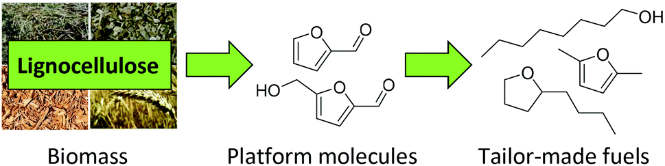 | ||
| Fig. 1 Conversion of lignocellulose into tailor-made fuels. | ||
The conversion of sugar-derived platform chemicals into diesel fuels requires an enlargement of the carbon chain and a reduction of the oxygen content. Strategies for C–C coupling include aldol-condensation, Diels–Alder reactions or electrophilic aromatic substitutions.14–16 Dumesic and coworkers were the first to suggest the condensation of furfural and HMF with acetone to form C8–C15 aldol products which can be subsequently hydrodeoxygenated to yield hydrocarbon jet and diesel range fuels.17 The resulting C8–C15 hydrocarbons are comparable to conventional diesel fuels produced from crude oil, and can therefore be used as drop-in fuels without adjustment of the engines. Thus, this idea got a lot of attention and was further investigated in other works.17–22
Nevertheless, the oxygen rich feedstock for biofuels opens the possibility to design new types of fuels with improved properties by keeping some of the functionalities in the molecules. In particular, several examples showed that the combustion of oxygenates (alcohols, ethers, etc.) generates less soot than with hydrocarbons.23–25 In this context, Leitner et al. recently identified three molecules (2-butyltertrahydrofuran (BTHF), 1-octanol (1-OL) and dioctylether (DOE) derived from furfuralacetone (FFA) as promising fuel candidates.26 While 1-octanol was already successfully tested as blending, the suitability of the other two components has still to be confirmed in real combustion engines.
The synthesis of BTHF, 1-OL and DOE was achieved via a two-step reaction concept. First FFA was hydrogenated over a commercial Ru/C catalyst and then the resulting saturated alcohol was deoxygenated using a bifunctional catalytic system consisting of Ru-nanoparticles stabilised in an acidic ionic liquid. While several catalysts have been reported for the one-pot hydrodeoxygenation of various aromatic ketones,27,28 the separation of the hydrogenation and the deoxygenation steps was necessary in this case in order to avoid the polymerization/degradation of FFA under acidic conditions.26 Later, an improved catalytic system was developed, consisting of Ru-nanoparticles immobilised on an acidic SILP (supported ionic liquid phase) material.29 Depending on the reaction conditions, the selectivity of the hydrodeoxygenation reaction could be shifted to either one of the three products. However, the reaction conditions still involved the use of an ionic liquid as solvent, hindering large-scale and continuous flow applications. As a result, the hydrodeoxygenation of furfuralacetone was so far limited to high pressure (120 bar) batch conditions.
In this work we present the first continuous flow production of BTHF from FFA using commercial catalysts for both hydrogenation and hydrodeoxygenation steps (Scheme 1). First, furfuralacetone was hydrogenated over a Ru/C catalyst, followed by the hydrodeoxygenation of the resulting alcohol (THFA) catalysed by a combination of Ru/C and an acidic ion exchange resin. Both reactions were first independently optimised in batch experiments before being taken to a continuous flow miniplant. Finally, both reactions were sequentially performed in a custom-built continuous flow miniplant to validate the two-reactor concept on the long-term. The two-step approach prevented the undesired formation of humins and allowed producing BTHF continuously in high yield and selectivity.
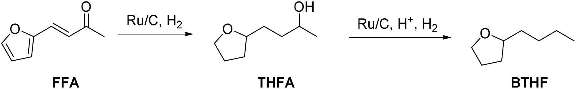 | ||
| Scheme 1 Two-step route from furfuralacetone (FFA) via 4-(tetrahydrofuran-2-yl)butan-2-ol (THFA) to the potential biofuel 2-butyltetrahydrofuran (BTHF). | ||
Experimental details
Safety warning
High-pressure experiments with compressed H2(g) must be carried out only with appropriate equipment and under rigorous safety precautions.General
Ru, 5% on carbon was purchased from abcr und used without further pre-treatment. All ion-exchange resins were bought from Sigma Aldrich. The polystyrene-based ion-exchange resins were washed with deionised water and methanol and dried at 100 °C over night prior to use. Hydrogen (5.0) was supplied by Westfalen. All batch experiments were carried out in 10 mL stainless steel high-pressure autoclaves with glass inserts.Gas chromatography
Gas Chromatography (GC) was used to determine the product yields in batch and continuous flow experiments using tetradecane (99%, abcr) as an internal standard. GC samples were prepared by diluting around 250 mg of filtered product solution with pure solvent. The samples were measured on a Shimadzu Chromatograph Nexis GC-2030 equipped with a FID detector and a CP-WAX-52CB column using tetradecane as internal standard. The response factors of FFA, THFK, THFA, BTHF, 1-OL and DOE were determined by calibration of the pure components. Response factors of compounds, which were not available as pure substance, were estimated using Sternberg's effective carbon method.30 The values for the mass balance were between 95% and 102% for the hydrogenation of FFA and between 91% and 97% for the deoxygenation of THFA.NMR spectroscopy
1H-NMR and 13C-NMR spectra of the isolated products were recorded on a Bruker AV400 (1H 400.2 MHz, 13C 100.6 MHz) spectrometer at room temperature. As solvent CDCl3 (residue signal at 7.2 ppm in 1H and 77.1 ppm in 13C) was used and its residue signal served as reference for the calibration of the spectra.Synthesis of the starting material furfuralacetone
Furfural was distilled under reduced pressure and stored under argon atmosphere in the freezer prior to use. furfural (58 g, 0.6 mol) and acetone (78 g, 1.3 mol) were dissolved in H2O (470 mL) and cooled to 10 °C. While stirring, a 33 wt% NaOH solution (13 mL) was added. After stirring at rt. for 4 h, the mixture was acidified with 20 wt% H2SO4 (25 ml). The product phase separated from the aqueous phase on standing and was removed. The aqueous phase was extracted with EtOAc (1 × 150 mL) and the organic phases were combined. After removal of solvent under reduced pressure, the crude product was purified by vacuum sublimation. Furfuralacetone was obtained as a white solid and stored under argon at 5 °C.Batch hydrogenation of furfuralacetone
In a typical experiment, FFA (102.1 mg, 0.75 mmol), 5 wt% Ru/C (7.6 mg, 3.75 μmol Ru), the internal standard tetradecane (20 mg) and cyclohexane (1.5 mL) were combined in a glass insert and placed in a 10 mL high-pressure autoclave. The autoclave was purged with H2 and then pressurised to 40 bar. The reaction mixture was stirred at 100 °C for 2 h. Once the reaction was finished, the reactor was cooled to room temperature and carefully vented. The product mixture was diluted, filtered through a syringe filter and analysed via GC-FID.Batch deoxygenation of 4-(tetrahydrofuran-2-yl)butan-2-ol
Pure THFA was obtained from hydrogenation product solutions by vacuum distillation. In a typical experiment, THFA (108 mg, 0.75 mmol), 5 wt% Ru/C (7.6 mg, 3.75 μmol Ru), Amberlyst 36 (9.3 mg, 0.05 mmol H+), 20 mg tetradecane and 1.5 mL cyclohexane were combined in a glass insert and placed in a 10 mL high-pressure autoclave. The autoclave was purged with H2 and then pressurised to 80 bar. The reaction mixture was stirred at 150 °C for 6 h. Once the reaction was finished, the reactor was cooled to room temperature and carefully vented. The product mixture was diluted with acetone, filtered through a syringe filter and analysed via GC-FID.Monitoring the course of the reaction
To monitor the deoxygenation of THFA, the reaction was carried out in a 50 mL autoclave with a sampling device. For this, the reaction was scaled up to 15 mL. The volume of each sample was approximately 0.2 mL.Continuous flow reactions
Continuous flow experiments were performed with a custom-built miniplant from Separex (Fig. 2). Depending on the configuration, the miniplant could be equipped with either one or two stainless steel tube reactors (35 cm long, 8.8 mm internal diameter) in series. The reactors were filled with alternating layers of the inert material SiC (46 grit, ≈3 g per layer) and catalyst. For the hydrogenation step, 1 g of Ru/C was used (125 mg per layer). In case of the deoxygenation, different amounts of Ru/C and Amberlyst 36 were physically mixed to form the catalyst layer. Both ends of the tube reactors were plugged with glass wool and stainless steel frits before and after the reactors to keep the catalyst bed in place. The dead volume of the filled tube reactors was approximately 11 mL. Heating jackets around the reactors provided the necessary heat for the reactions. Hydrogen flow was controlled by a mass flow controller (Bronkhorst F-230 M). The flow rate of the substrate solution was controlled by an HPLC pump (SSI Model 12-6 dual piston pump). Once the hydrogen and substrate flows were combined, the resulting stream passed through a tube filled with glass beads for a pre-mixing of the two phases, as well as a pre-heater before reaching the reactor. A back-pressure regulator controlled the pressure inside the miniplant (fluctuation <±1 bar). Samples of the product stream were taken periodically.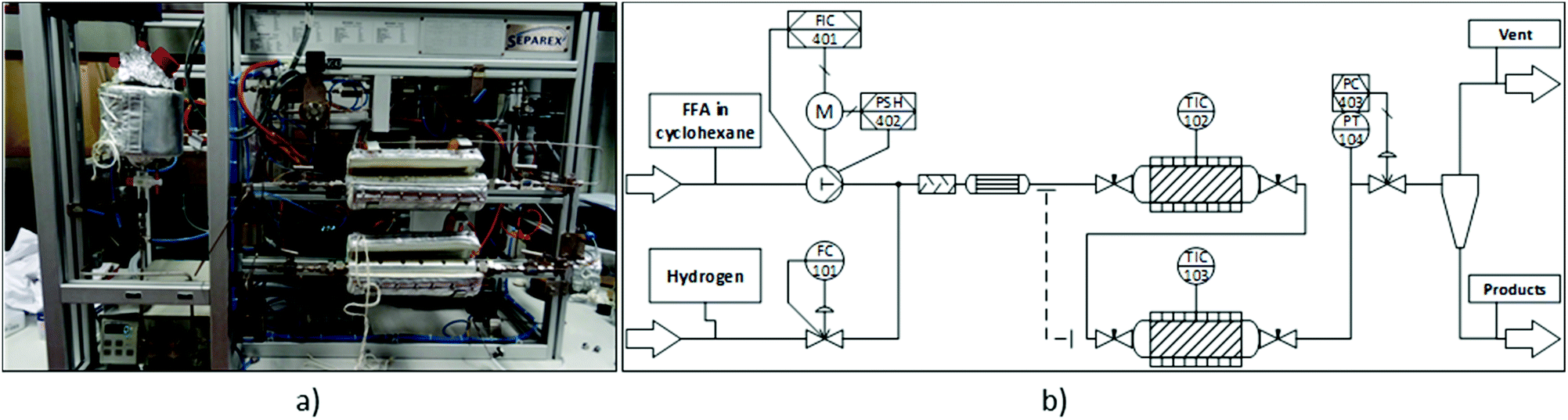 | ||
| Fig. 2 Continuous flow miniplant used in this study. (a) Picture of the miniplant. (b) Simplified process diagram. | ||
Results and discussion
Step 1: Furfuralacetone hydrogenation in batch
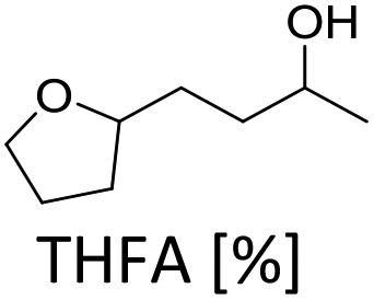
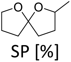
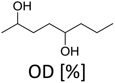
Furfuralacetone is a quite complex molecule bearing three different types of unsaturated functionalities, namely a C–C double bond, a keto group and a furan ring. As a result, the hydrogenation of FFA leads to the formation of different products, depending on the reaction conditions. Scheme 2 gives an overview of all species that were observed during this work and the proposed pathways leading to those species. The reaction network is in accordance with the literature.31,32 The rapid hydrogenation of the double bond in FFA gives the intermediate 4-(furan-2-yl)butan-2-one (FK). FK can be further converted to either 4-(furan-2-yl)butan-2-ol (FA) by hydrogenation of the keto group or to 4-(tetrahydrofuran-2-yl)butan-2-one (THFK), if the aromatic ring is hydrogenated first. In another hydrogenation step FA and THFK can both be transformed to the saturated molecule 4-(tetrahydrofuran-2-yl)butan-2-ol (THFA). Two additional products that have been observed are 2-methyl-1,6-dioxaspiro[4.4]nonane (SP) and octane-2,5-diol (OD). The formation of SP from FA has been reported before.33 It is formed via the partially hydrogenated intermediate 4-(4,5-dihydrofuran-2-yl)butan-2-ol (DHFA) which was not observed because of its high reactivity. The formation of OD requires an opening of the five-membered ring and takes place most likely while the aromatic ring is still intact, since the saturated ring is known to be more stable towards hydrogenolysis.34,35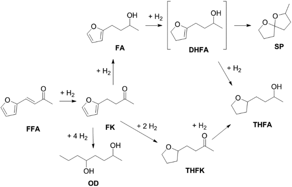 | ||
| Scheme 2 Reaction network for the hydrogenation of furfuralacetone (FFA). OD = octane-2,5-diol FK = 4-(furan-2-yl)butan-2-one, FA = 4-(furan-2-yl)butan-2-ol, THFK = 4-(tetrahydrofuran-2-yl)butan-2-one, DHFA = 4-(4,5-dihydrofuran-2-yl)butan-2-ol, THFA = 4-(tetrahydrofuran-2-yl)butan-2-ol, SP = 2-methyl-1,6-dioxaspiro[4.4]nonane. | ||
Initial experiments were performed in batch mode using stainless steel autoclave reactors (Table 1). Commercially available Ru/C served as hydrogenation catalyst since it already gave successful results in previous works26 and showed better selectivity or activity compared to other metal catalysts (see ESI Table S1†). Only Ru/Al2O3 gave similar results, however flow experiments revealed a strong deactivation over time. For the hydrogenation step, the use of additional acids was excluded since FFA is prone to form humins in their presence. We selected cyclohexane as solvent for the reaction because it is inert under hydrogenation as well as deoxygenation conditions. However, the solubility of FFA in cyclohexane at room temperature is relatively low, so only a concentration of 0.5 mol l−1 was possible. The hydrogenation of FFA showed a minor dependence of the product distribution on the reaction temperature (entries 1.1–1.4). Nevertheless, at 50 °C the highest yield towards the formation of THFA (92%) was achieved (entry 1.1). Variation of the hydrogen pressure revealed that high pressures prevent the formation of the side product SP. While at 20 bar hydrogen pressure 14% of SP were formed, the amount was reduced to 4% at 80 bar (entries 1.5–1.6). An additional increase to 120 bar did not improve the THFA yield further as still 3% SP were formed (entry 1.7). Using THF instead of cyclohexane as solvent also led to a decrease in side products formation. However, due to the lower hydrogen solubility in THF, the reaction proceeded at a slower rate, and 8% of the intermediate THFK remained after the reaction (entry 1.8). Under solvent-free conditions, the THFA yield was similar to what was observed in cyclohexane (entry 1.9). These batch results demonstrate that Ru/C can rapidly fully hydrogenate FFA in cyclohexane. Under optimised conditions (50 °C, 80 bar) full conversion and a yield towards THFA of 95% was reached (entry 1.10).
| Entry | T [°C] | p [bar] |
|
|
|
|---|---|---|---|---|---|
| a Conditions: FFA (0.75 mmol), Ru/C (3.75 μmol Ru), H2, cyclohexane (1.5 mL), 2 h. Product yields were determined by GC-FID using tetradecane as internal standard. b THF (1.5 mL). c No solvent. | |||||
| 1.1 | 50 | 40 | 92 | 5 | 3 |
| 1.2 | 100 | 40 | 88 | 8 | 3 |
| 1.3 | 120 | 40 | 88 | 8 | 2 |
| 1.4 | 150 | 40 | 87 | 9 | 1 |
| 1.5 | 100 | 20 | 81 | 14 | 5 |
| 1.6 | 100 | 80 | 93 | 4 | 3 |
| 1.7 | 100 | 120 | 94 | 3 | 2 |
| 1.8b | 100 | 40 | 87 | 3 | 2 |
| 1.9c | 100 | 40 | 86 | 10 | 4 |
| 1.10 | 50 | 80 | 95 | 2 | 2 |
In order to verify the heterogeneous nature of the catalyst, we determined the ruthenium content in the product solution by ICP-MS and tested the catalytic activity of the filtrate after removal of the catalyst. A very low Ru concentration (7 ppb) and no activity after catalyst removal confirm that neither nanoparticles nor molecular species leach into the liquid phase.
Step 2: 4-(Tetrahydrofuran-2-yl)butan-2-ol hydrodeoxygenation in batch
The hydrodeoxygenation of THFA involves a complex reaction network of hydrogenation and hydrogenolysis reactions, which is outlined in Scheme 3. Through the desired pathway, THFA reacts in acidic conditions to give 2-butyltetrahydrofuran (BTHF) via elimination of the hydroxyl group. Side reactions include the reversible formation of THFA isomers and dimerisation. One THFA isomer can also react irreversible to 2-methyl-5-propyltetrahydrofuran (MPTHF). Opening of the five-membered ring in BTHF can lead to either the cyclic isomerization product 2-propyltetrahydro-2H-pyran (PTHP) or the linear 1-octanol (1-OL). Additional side products include dioctylether (DOE), octane and the C7-molecules such as heptane and 2-methyl-5-ethyltetrahydrofuran. The main side products, PTHP and 1-OL, are potential biofuel molecules, too. Nevertheless, our aim was to maximise the yield of BTHF during the hydrodeoxygenation.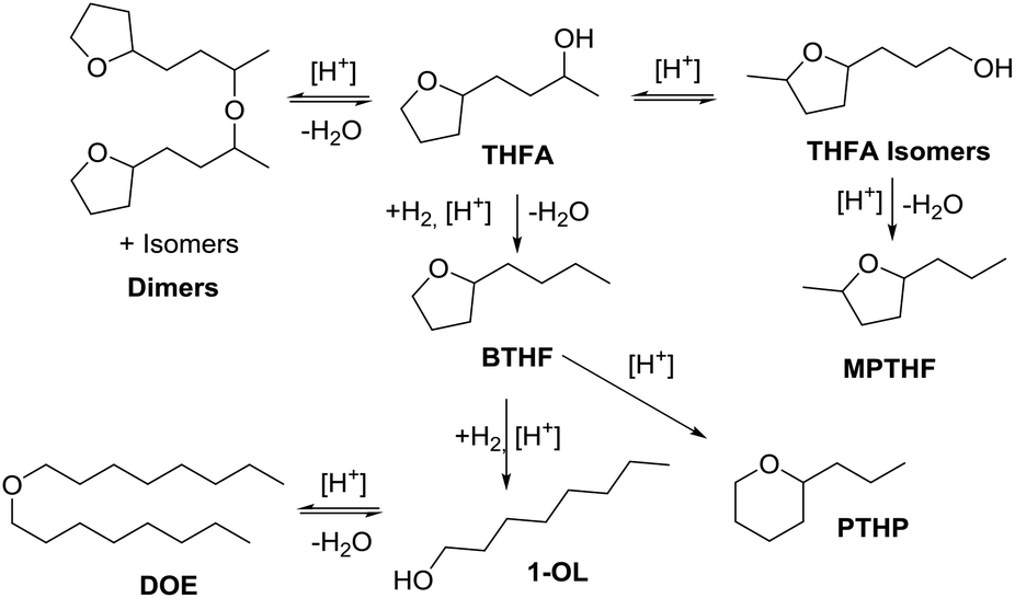 | ||
| Scheme 3 Reaction network for the deoxygenation of 4-(tetrahydrofuran-2-yl)butan-2-ol (THFA). BTHF = 2-butyltetrahydrofuran, PTHP = 2-propyltetrahydro-2H-pyran, MPTHF = 2-methyl-5-propyltetrahydrofuran, 1-OL = 1-octanol, DOE = dioctylether. | ||
Preliminary optimisation experiments of the reaction parameters based on a design of experiment approach suggested a temperature of 150 °C, a hydrogen pressure of 80 bar, a reaction time of 6 h and a substrate to H+ ratio of 15![[thin space (1/6-em)]](https://www.rsc.org/images/entities/char_2009.gif) :1 (see ESI Tables S2 and S3†). With these optimised conditions in hand, we investigated the time profile of the reaction, which is displayed in Fig. 3. During the first three hours, BTHF and dimers are formed likewise. Afterwards, as more BTHF is produced and THFA is withdrawn from the equilibrium, the amount of dimers decreases again. At four hours, BTHF reaches its maximum with 94%, before the consecutive reactions to PTHP and 1-OL become pronounced.
:1 (see ESI Tables S2 and S3†). With these optimised conditions in hand, we investigated the time profile of the reaction, which is displayed in Fig. 3. During the first three hours, BTHF and dimers are formed likewise. Afterwards, as more BTHF is produced and THFA is withdrawn from the equilibrium, the amount of dimers decreases again. At four hours, BTHF reaches its maximum with 94%, before the consecutive reactions to PTHP and 1-OL become pronounced.
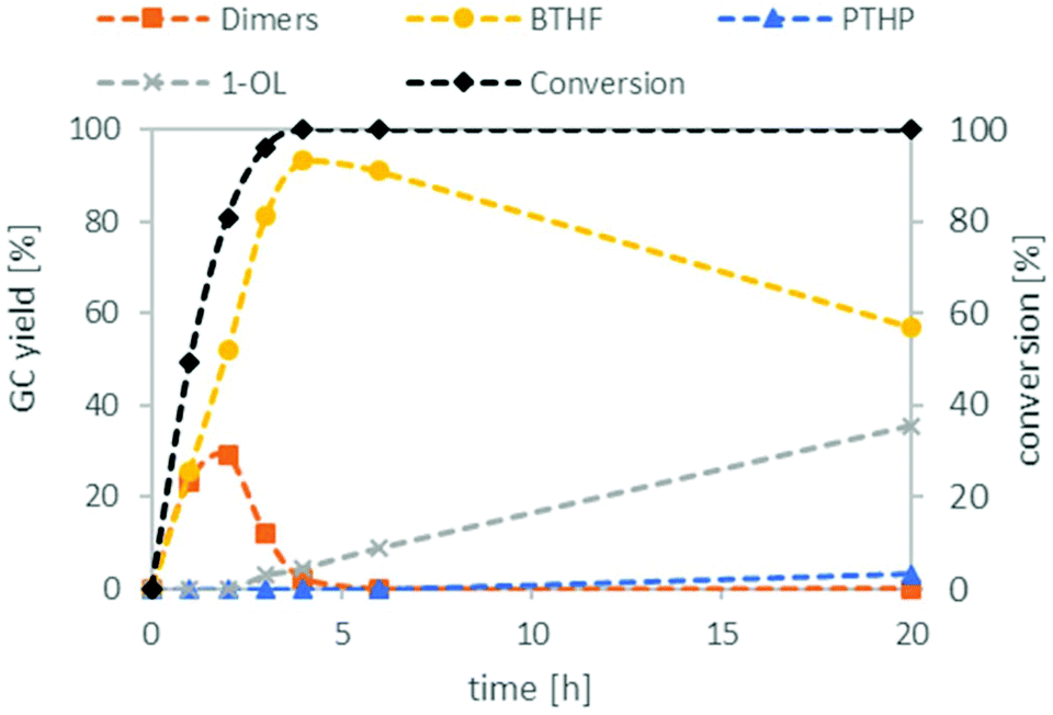 | ||
| Fig. 3 Reaction profile for the deoxygenation of THFA. THFA (7.5 mmol), Ru/C (0.038 mmol Ru), Amberlyst 36 (0.5 mmol H+), H2 (80 bar), 150 °C, cyclohexane (15 mL). | ||
Next, we compared different ion-exchange resins as solid acid components for the deoxygenation step. The reaction temperature of 150 °C is a limiting factor, because many resins such as Amberlyst 15 are only stable up to 120 °C. Thus, we selected four different ion exchange resins with high thermal stability. Dowex 50WX8, Dowex Marathon MSC and Amberlyst 36 tolerate temperatures up to 150 °C and Nafion NR50 up to 200 °C. As shown in Fig. 4, the resins Dowex Marathon and Amberlyst 36 gave the highest BTHF yields with 83% and 91%, respectively. Dowex 50 seems to be less active because after 6 h still 23% of the starting material remains in form of dimers. The lower activity of Dowex 50 is probably a consequence of its gel-type matrix. Gel-type exchange resins need to swell in the solvent for an optimal access of the acid sides, which is why they are less suitable for apolar solvents such as cyclohexane.36 Dowex Marathon and Amberlyst 36 are macroporous ion-exchange resins with good access of the acid sides even in non-swelling solvents and thus give better results. The ion exchange resin Nafion NR50 showed the highest deoxygenation activity and led to high fractions of the consecutive products PTHP (19%) and 1-OL (11%). The reason for this is the higher acid strength of Nafion NR50 compared to the polystyrene-based exchange resins.36 Although Nafion NR50 is also based on a gel-type matrix, the higher acid strength dominates in this case. The increased formation of side-products and the resulting lower BTHF yield (70%) exclude Nafion as a suitable solid acid.
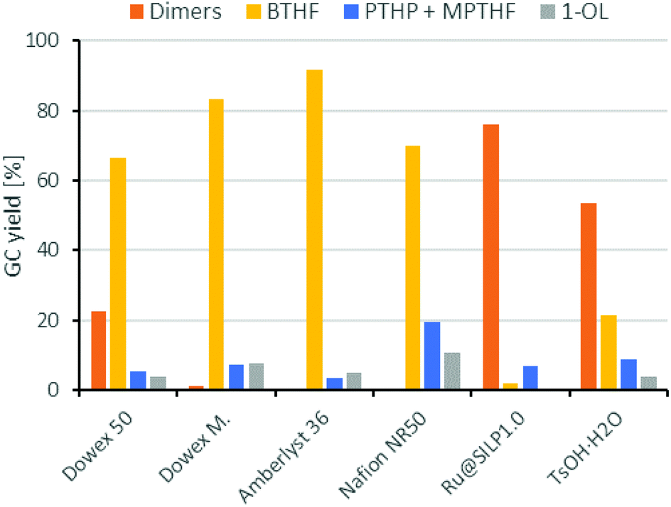 | ||
| Fig. 4 Comparison of different acid components for the deoxygenation of THFA. Conditions: THFA (0.75 mmol), Ru/C (3.75 μmol Rul), H+ (0.05 mmol), H2 (80 bar), 150 °C, cyclohexane (1.5 mL), 6 h. | ||
Ruthenium nanoparticles immobilised on an sulfonic acid-functionalised SILP material (Ru@SILP1.0), which showed excellent deoxygenation results in a previous work by Luska et al.,29 were tested as well. Surprisingly, under our modified reaction conditions – that differed mainly from the previous ones through the use of cyclohexane as solvent instead of the ionic liquid [EMIM][NTf2] – hardly any BTHF or 1-OL formation was observed. Instead, only the dimerisation of FFA took place. These results indicate that the ionic liquid not only served as a solvent in this case, but actively interferes in the reaction mechanism. It is known that ionic liquids can influence catalytic reactions by stabilising intermediates such as carbenium ions or enhance the strength of acids, which could explain the strong differences of the product distribution for different solvents.37 Finally, we tried p-toluenesulfonic acid monohydrate as a homogeneous acid catalyst. TsOH produced less BTHF than the ion-exchange resins as mainly dimers were formed during the deoxygenation reaction, although the Dowex and Amberlyst resins contain the same sulfonic acid group as TsOH. Gates et al. also observed this trend in the dehydration of t-butyl alcohol. To explain this, the authors presented a concerted mechanism including multiple –SO3H groups. This mechanism is more likely to take place in an exchange resin with high local concentration of acid groups.38
Overall Amberlyst 36 showed the best performance with the highest yield of the target molecule BTHF (ca. 92%) and only small amounts of undesired isomeric side products. Therefore, Amberlyst 36 was selected as acid catalyst for the rest of the study.
Next, we studied the influence of the solvent on the product distribution (Fig. 5). While the hydrogenation of FFA proceeded smoothly in both cyclohexane and THF to give THFA in high yields (ca. 90%), THF was not inert under the acidic conditions used for the hydrodeoxygenation reaction. Significant amounts of 1-butanol, the hydrogenolysis product of THF, were indeed observed during the reaction. Ring opening of the solvent took also place in case of 1,4-dioxane or 2-methyltetrahydrofuran. Under solvent-free conditions, BTHF was formed as the main product (76% yield). The lower yield, compared to the reactions in cyclohexane, comes along with a higher amount of 1-OL (19%). As 1-OL is a consecutive product of BTHF, probably better BTHF yields could be achieved with a shorter reaction time in this case. Surprisingly, a completely different product distribution was obtained when the deoxygenation of THFA was performed in the ionic liquid 1-ethyl-3-methylimidazolium bis(trifluoro-methylsulfonyl)imide ([EMIM][NTf2]), which was used in earlier works.26,29 Instead of BTHF, almost exclusively 1-OL and its etherification product dioctylether (DOE) were formed. As mentioned above, the ionic liquid influences the catalysis considerably. Despite octanol being a valuable chemical, the use of an expensive ionic liquid seems not justified, nor suitable for large scale applications.39 While neat conditions would be of course beneficial compared to cyclohexane in terms of economy and green chemistry, the solvent-free implementation into our miniplant was not practical, because FFA is a solid at room temperature. Thus, cyclohexane was used for our continuous flow experiments.
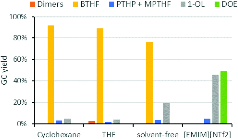 | ||
| Fig. 5 Influence of the solvent on the deoxygenation of THFA. Conditions: THFA (0.75 mmol), Ru/C (3.75 μmol Ru), Amberlyst-36 (9.3 mg, 0.05 mmol H+), H2 (80 bar), 150 °C, 6 h, solvent (1.5 mL). [Emim][NTf2] = 1-ethyl-3-methylimidazolium bis(trifluoromethylsulfonyl)imide. | ||
Step 1 & 2: Hydrogenation and deoxygenation of furfuralacetone in batch
Finally, we carried out both reaction steps in a row in a one-pot approach, using the conditions determined in the previous optimisation (Fig. 6). For this, FFA, Ru/C and Amberlyst 36 were all combined in the beginning and pressurised with hydrogen. The mixture was then stirred for 2 h at 50 °C. At this temperature no polymerisation of FFA took place despite the presence of the acidic Amberlyst 36. Afterwards the temperature was elevated to 150 °C and the mixture was stirred for another 6 h. The tandem reaction approach gave an overall BTHF yield of 91%. This was even higher than the combined yield of the two individual steps (95%·92% = 87%), because some of the SP side product, formed in the first step can react to THFA and further to BTHF under deoxygenation conditions.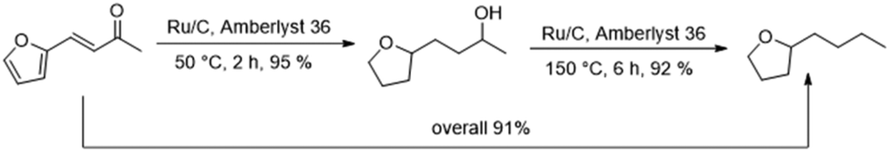 | ||
| Fig. 6 One-pot two steps hydrodeoxygenation of FFA to BTHF. | ||
Continuous flow experiments
After investigation of both reaction steps in batch conditions, the reaction system was transferred to a continuous flow miniplant. The miniplant was equipped with two tubular reactors in series so that two consecutive reactions can take place one after the other without workup or change of the pressure in between.Continuous operation step 1: hydrogenation
Following an approach similar to what was previously described for the batch experiments, we studied both reaction steps individually starting with the hydrogenation of FFA. Based on results obtained in batch, cyclohexane was used as solvent and the pressure was set to 80 bar. The temperature was investigated between 50 °C to 120 °C. Table 2 compares the yield of THFA depending on the temperatures after 3 h on stream. Good THFA yields of 94%–97% were obtained at all investigated temperatures, whereby 50 °C gave the highest yield, in accordance to the batch experiments. However, at reaction temperatures of 80 °C or higher these yields were only stable for the first couple of hours. After around 5–6 h on stream, the THFA yield decreased drastically as more of the intermediate THFK remained in the product solution (see ESI Fig. S1 to S3†). It was concluded that the catalyst suffered from deactivation. Fortunately, at 50 °C the yield of THFA stayed stable at 96–97% throughout the entire experiment of 10 h (Fig. 7). To understand the nature of the deactivation we characterized the Ru/C catalyst by transmission electron microscopy (TEM) and X-ray diffraction (XRD) analysis before and after deactivation took place. TEM pictures showed no clustering of the Ru-particles and the structure of the support did not change significantly either during the reaction. Furthermore, Ru-leaching into the solution was also negligible, as ICP-OES analysis only showed ppb-amounts of Ru in the product solution. As a result, the most likely reason for the catalyst deactivation is poisoning or blockage of the Ru-centres by deposition of an insoluble side product. This presumption is furthermore supported by BET (Brunauer–Emmett–Teller) and TG (thermal gravimetric) analysis. The BET data show a significant reduction of surface area and pore volume of the catalyst after the reaction (see ESI, Fig. S7†). In addition, TGA revealed a weight loss of the catalyst when heating it over 250 °C (see ESI, Fig. S6†).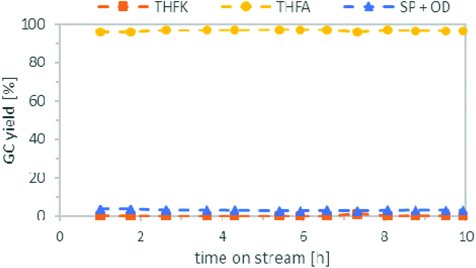 | ||
| Fig. 7 Continuous Flow Hydrogenation of a FFA (0.25 mol L−1) solution in cyclohexane. Conditions: Catalyst bed: 1 g Ru/C, 50 °C, substrate flowrate: 1 mL min−1, hydrogen flowrate: 37 mLN min−1, pressure: 80 bar, WHSV = 2 h−1. | ||
| Entry | T [°C] | THFA yield after 3 h [%] | Catalyst deactivation |
|---|---|---|---|
| a Conditions: FFA solution in cyclohexane (0.25 mol L−1), catalyst bed: 1 g Ru/C, substrate flowrate: 1 mL min−1, hydrogen flowrate: 37 mLN min−1, pressure: 80 bar, WHSV = 2 h−1. b Experiment lasted 10 h. | |||
| 2.1 | 50 | 97 | Nob |
| 2.2 | 80 | 95 | Yes |
| 2.3 | 100 | 95 | Yes |
| 2.4 | 120 | 94 | Yes |
Continuous operation step 2: deoxygenation
We continued with the investigation of the hydrodeoxygenation step in a continuously operated system (Table 3). As evidenced during our study under batch conditions, the residence time must be chosen correctly to achieve a high yield of the desired BTHF. Therefore, we varied the substrate flow and the amount of Amberlyst 36, which both influence the residence time. We started with a flow rate of 0.25 mL min−1 and 2 g of Amberlyst 36 for the first try. In addition to the side products observed during the batch experiments, significant amounts of octane, heptane and 2-methyl-5-ethyltetrahydrofuran were formed under these conditions. Additionally, 11% of dimers were left after the reaction, indicating that the residence time was too short (entry 3.1). To extend the contact time of substrate and catalyst, we increased the amount of the ion-exchange resin to 6 g for the next run. As a result, no dimers remained after the reaction. However, even more C7 species were observed compared to the previous run (entry 3.2). Surprisingly, still all dimers were converted, when the substrate flow rate was increased to 0.38 or even 1.0 mL min−1 (entries 3.3–3.4). At the same time, the formation of undesired octane and C7 species was significantly reduced to 5%, thus leading to a BTHF yield of 85%. The amount of MTHF and 1-OL was not significantly influenced by the change of the substrate flow rate.| Entry | Substrate flowrate [mL min−1] | Amberlyst 36 [g] | Dimers [%] | BTHF [%] | C7 + octane [%] | MPTHF + 1-OL [%] |
|---|---|---|---|---|---|---|
| a Conditions: Catalyst bed: 2 g Ru/C + Amberlyst 36, 150 °C, hydrogen flowrate: 13 mLN min−1, pressure: 80 bar. C7 = n-heptane and 2-methyl-5-ethyltetrahydrofuran. Results were obtained after the conversion of 20 mmol of substrate. | ||||||
| 3.1 | 0.25 | 2 | 11 | 68 | 13 | 7 |
| 3.2 | 0.25 | 6 | 0 | 74 | 17 | 9 |
| 3.3 | 0.38 | 6 | 0 | 79 | 9 | 11 |
| 3.4 | 1.0 | 6 | 0 | 85 | 5 | 9 |
Continuous operation step 1 & 2
Finally, we combined both steps in the miniplant, using the optimised conditions found earlier. For the deoxygenation, we reduced the amount of Ru/C from 2 g to 1 g, because there were indications (see ESI, Table S4†) that this might further reduce the formation of the C7 species. The results can be seen in Fig. 8. During the first 4.5 h, a good BTHF yield of 86–87% was achieved, no dimers were formed in the product mixture and the amount of C7 species and octane was only 2–3%. In the remaining time, the amount of BTHF decreased steadily, as the amount of dimers increased. After 10.5 h on stream, the yield of BTHF was reduced to 75% and the dimers were increased to 16%. We assume that the loss of activity is due to the formation of water which is produced as a by-product during the deoxygenation. Since water is not miscible with cyclohexane, it is suspected that it stays adsorbed on the Amberlyst 36. This would consistent with findings of other groups that water reduces the strength of Brønsted acids in deoxygenation reactions.40,41 One approach to counteract the decrease in activity could be to reduce the flow rate constantly over time. However, this assumes that the catalyst deactivation reaches a saturation level, as the course of the yield in Fig. 8 suggests and does not progress constantly. Another idea would be to add a drying agent to the catalyst bed to remove the water temporary from the catalyst and change the used reactor from time to time. In any case, this issue needs further investigation and longer time on stream data in the future.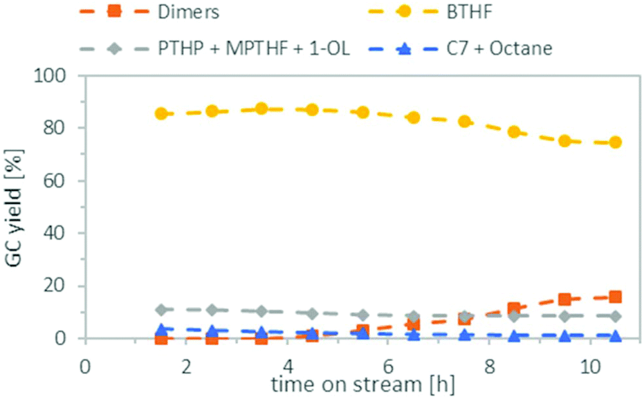 | ||
| Fig. 8 Continuous flow hydrogenation and deoxygenation of a FFA solution (0.25 mol L−1) in cyclohexane. Conditions: Catalyst bed 1st reactor: 1 g Ru/C, 50 °C, WHSV = 2 h−1, catalyst bed 2nd reactor: 1 g Ru/C + 6 g Amberlyst 36, 150 °C, WHSV = 0.29 h−1, substrate flowrate: 1 mL min−1, hydrogen flowrate: 50 mLN min−1, pressure: 80 bar. C7 = n-heptane and 2-methyl-5-ethyltetrahydrofuran. | ||
Conclusions
A two-step approach for the conversion of lignocellulose-based furfuralacetone to 2-butyltetrahydrofuran is presented. Complete hydrogenation of furfuralacetone is rapidly achieved at 50 °C over a commercial Ru/C catalyst with excellent yields of up to 97%. The hydrogenation product THFA is then deoxygenated to 2-butyltetrahydrofuran in the second step by metal and acid catalysis. A combination of the commercial catalysts Ru/C and the ion exchange resin Amberlyst 36 were found to be best suited for this transformation. In comparison to other ion exchange resins, Amberlyst 36 lead to the highest BTHF yield of 92% in batch experiments. Furthermore, the combination of inexpensive heterogeneous catalysts and cyclohexane as solvent, allowed the implementation of this reaction cascade into a custom-built miniplant. To best of our knowledge this is first continuous flow synthesis of BTHF based on renewable resources. Both reaction steps are successfully performed in sequence in the miniplant with an initial BTHF yield of 86–87%. After 5 h on stream, the yield starts to decrease slowly down to 75% after 10 h due to deactivation of the ion-exchange resin.Further investigations should deal with this deactivation by water and include longer continuous flow experiments. Additionally, a continuous implementation of the reaction sequence based on solvent-free conditions could be considered.
Conflicts of interest
There are no conflicts to declare.Acknowledgements
The authors would like to thank Dr Saskia Heumann for XRD and TEM measurements, as well as Sarah Bormann for her help with the experiments. Furthermore, we gratefully acknowledge the support by the Max-Planck-Society. Open Access funding provided by the Max Planck Society.Notes and references
- A. Corma, S. Iborra and A. Velty, Chem. Rev., 2007, 107, 2411–2502 CrossRef CAS PubMed.
- D. M. Alonso, J. Q. Bond and J. A. Dumesic, Green Chem., 2010, 12, 1493–1513 RSC.
- G. W. Huber, S. Iborra and A. Corma, Chem. Rev., 2006, 106, 4044–4098 CrossRef CAS PubMed.
- P. Gallezot, Chem. Soc. Rev., 2012, 41, 1538–1558 RSC.
- Z. Zhang, J. Song and B. Han, Chem. Rev., 2017, 117, 6834–6880 CrossRef CAS PubMed.
- A. M. Ruppert, K. Weinberg and R. Palkovits, Angew. Chem., Int. Ed., 2012, 51, 2564–2601 CrossRef CAS PubMed.
- J. S. Luterbacher, D. Martin Alonso and J. A. Dumesic, Green Chem., 2014, 16, 4816–4838 RSC.
- L. T. Mika, E. Cséfalvay and Á. Németh, Chem. Rev., 2018, 118, 505–613 CrossRef CAS PubMed.
- X. Kong, Y. Zhu, Z. Fang, J. A. Kozinski, I. S. Butler, L. Xu, H. Song and X. Wei, Green Chem., 2018, 20, 3657–3682 RSC.
- S. Chen, R. Wojcieszak, F. Dumeignil, E. Marceau and S. Royer, Chem. Rev., 2018, 118, 11023–11117 CrossRef CAS PubMed.
- X. Li, P. Jia and T. Wang, ACS Catal., 2016, 6, 7621–7640 CrossRef CAS.
- W. Leitner, J. Klankermayer, S. Pischinger, H. Pitsch and K. Kohse-Höinghaus, Angew. Chem., Int. Ed., 2017, 56, 5412–5452 CrossRef CAS PubMed.
- M. Dahmen and W. Marquardt, Energy Fuels, 2016, 30, 1109–1134 CrossRef CAS.
- H. Zang, K. Wang, M. Zhang, R. Xie, L. Wang and E. Y. X. Chen, Catal. Sci. Technol., 2018, 8, 1777–1798 RSC.
- H. Li, A. Riisager, S. Saravanamurugan, A. Pandey, R. S. Sangwan, S. Yang and R. Luque, ACS Catal., 2017, 8, 148–187 CrossRef.
- A. Behr, A. J. Vorholt, K. A. Ostrowski and T. Seidensticker, Green Chem., 2014, 16, 982–1006 RSC.
- G. W. Huber, J. N. Chheda, C. J. Barrett and J. A. Dumesic, Science, 2005, 308, 1446–1450 CrossRef CAS PubMed.
- Q.-N. Xia, Q. Cuan, X.-H. Liu, X.-Q. Gong, G.-Z. Lu and Y.-Q. Wang, Angew. Chem., Int. Ed., 2014, 53, 9755–9760 CrossRef CAS PubMed.
- G. Li, N. Li, J. Yang, A. Wang, X. Wang, Y. Cong and T. Zhang, Bioresour. Technol., 2013, 134, 66–72 CrossRef CAS PubMed.
- W. Xu, Q. Xia, Y. Zhang, Y. Guo, Y. Wang and G. Lu, ChemSusChem, 2011, 4, 1758–1761 CrossRef CAS PubMed.
- J. Yang, N. Li, G. Li, W. Wang, A. Wang, X. Wang, Y. Cong and T. Zhang, ChemSusChem, 2013, 6, 1149–1152 CrossRef CAS PubMed.
- Q. Deng, J. Xu, P. Han, L. Pan, L. Wang, X. Zhang and J.-J. Zou, Fuel Process. Technol., 2016, 148, 361–366 CrossRef CAS.
- H. Liu, X. Bi, M. Huo, C.-f. F. Lee and M. Yao, Energy Fuels, 2012, 26, 1900–1911 CrossRef CAS.
- S. E. Iannuzzi, C. Barro, K. Boulouchos and J. Burger, Fuel, 2016, 167, 49–59 CrossRef CAS.
- J. Preuß, K. Munch and I. Denbratt, Fuel, 2018, 216, 890–897 CrossRef.
- J. Julis and W. Leitner, Angew. Chem., Int. Ed., 2012, 51, 8615–8619 CrossRef CAS PubMed.
- L. Offner-Marko, A. Bordet, G. Moos, S. Tricard, S. Rengshausen, B. Chaudret, K. L. Luska and W. Leitner, Angew. Chem., Int. Ed., 2018, 57, 12721–12726 CrossRef CAS PubMed.
- C. Schäfer, C. J. Ellstrom, H. Cho and B. Török, Green Chem., 2017, 19, 1230–1234 RSC.
- K. L. Luska, J. Julis, E. Stavitski, D. N. Zakharov, A. Adams and W. Leitner, Chem. Sci., 2014, 5, 4895–4905 RSC.
- J. T. Scanlon and D. E. Willis, J. Chromatogr. Sci., 1985, 23, 333–340 CAS.
- J. Julis, M. Hölscher and W. Leitner, Green Chem., 2010, 12, 1634–1639 RSC.
- R. Ramos, Z. Tišler, O. Kikhtyanin and D. Kubička, Catal. Sci. Technol., 2016, 6, 1829–1841 RSC.
- K. Alexander, L. S. Hafner and L. E. Schniepp, J. Am. Chem. Soc., 1951, 73, 2725–2726 CrossRef CAS.
- C. R. Waidmann, A. W. Pierpont, E. R. Batista, J. C. Gordon, R. L. Martin, L. A. (Pete) Silks, R. M. West and R. Wu, Catal. Sci. Technol., 2013, 3, 106–115 RSC.
- S. Koso, I. Furikado, A. Shimao, T. Miyazawa, K. Kunimori and K. Tomishige, Chem. Commun., 2009, 2035–2037, 10.1039/B822942B.
- M. A. Harmer and Q. Sun, Appl. Catal., A, 2001, 221, 45–62 CrossRef CAS.
- J. W. Lee, J. Y. Shin, Y. S. Chun, H. B. Jang, C. E. Song and S.-g. Lee, Acc. Chem. Res., 2010, 43, 985–994 CrossRef CAS PubMed.
- B. C. Gates, J. S. Wisnouskas and H. W. Heath, J. Catal., 1972, 24, 320–327 CrossRef CAS.
- P. G. Jessop, Green Chem., 2011, 13, 1391–1398 RSC.
- K. L. Luska, P. Migowski, S. El Sayed and W. Leitner, Angew. Chem., Int. Ed., 2015, 54, 15750–15755 CrossRef CAS PubMed.
- M. A. Mellmer, C. Sener, J. M. R. Gallo, J. S. Luterbacher, D. M. Alonso and J. A. Dumesic, Angew. Chem., Int. Ed., 2014, 53, 11872–11875 CrossRef CAS PubMed.
Footnote |
| † Electronic supplementary information (ESI) available. See DOI: 10.1039/c9gc02555c |
| This journal is © The Royal Society of Chemistry 2019 |