 Open Access Article
Paired electrocatalytic hydrogenation and oxidation of 5-(hydroxymethyl)furfural for efficient production of biomass-derived monomers†
Xiaotong H.
Chadderdon
 a,
David J.
Chadderdon
 a,
Toni
Pfennig
 ab,
Brent H.
Shanks
 ab and
Wenzhen
Li
 *ac
*ac
aDepartment of Chemical and Biological Engineering, Iowa State University, Ames 50011, USA. E-mail: wzli@iastate.edu
bNSF Engineering Research Center for Biorenewable Chemicals (CBiRC), Iowa State University, Ames 50011, USA
cUS Department of Energy Ames Laboratory, Ames 50011, USA
First published on 23rd October 2019
Abstract
Electrochemical conversion of biomass-derived compounds is a promising route for sustainable chemical production. Herein, we report unprecedentedly high efficiency for conversion of 5-(hydroxymethyl)furfural (HMF) to biobased monomers by pairing HMF reduction and oxidation half-reactions in one electrochemical cell. Electrocatalytic hydrogenation of HMF to 2,5-bis(hydroxymethyl)furan (BHMF) was achieved under mild conditions using carbon-supported Ag nanoparticles (Ag/C) as the cathode catalyst. The competition between Ag-catalyzed HMF hydrogenation to BHMF and undesired HMF hydrodimerization and hydrogen evolution reactions was sensitive to cathode potential. Also, the carbon support material in Ag/C was active for HMF reduction at strongly cathodic potentials, leading to additional hydrodimerization and low BHMF selectivity. Accordingly, precise control of the cathode potential was implemented to achieve high BHMF selectivity and efficiency. In contrast, the selectivity of HMF oxidation facilitated by a homogeneous electrocatalyst, 4-acetamido-TEMPO (ACT, TEMPO = 2,2,6,6-tetramethylpiperidine-1-oxyl), together with an inexpensive carbon felt electrode, was insensitive to anode potential. Thus, it was feasible to conduct HMF hydrogenation to BHMF and oxidation to 2,5-furandicarboxylic acid (FDCA) in a single divided cell operated under cathode potential control. Electrocatalytic HMF conversion in the paired cell achieved high yields of BHMF and FDCA (85% and 98%, respectively) and a combined electron efficiency of 187%, corresponding to a nearly two-fold enhancement compared to the unpaired cells.
1. Introduction
Organic electrosynthesis has emerged as a promising methodology for environmentally-friendly chemical production.1 In electroorganic reactions, electrons serve as an inherently clean reagent to replace stoichiometric oxidants or reductants, and thereby eliminate toxic waste and byproducts.2 The driving force of electrode reactions can be directly manipulated by controlling the potential, which may enable very high selectivity for desired molecular transformations.3–5 Moreover, the electrochemical cells may potentially be powered by electricity from renewable sources,6,7 reducing the overall carbon footprint. Despite these advantages, the industrial electrosynthesis of organic molecules has been very limited in terms of number of processes and production volumes.8 Factors limiting its widespread application are poor catalyst activity and reaction rates, as well as high energy demands.9Electrocatalytic hydrogenation (ECH) of biomass-derived molecules has received significant attention in recent years.10–16 ECH is analogous to thermal catalytic hydrogenation, with the key difference that surface-adsorbed hydrogen atoms are generated electrochemically from water or proton reduction, rather than from H2 dissociation.17 In this way, the large kinetic barriers for H2 dissociation are avoided, therefore allowing ECH to proceed at mild temperatures and pressures and without the need for conventional hydrogenation catalysts (e.g., Pt, Pd, Ni). However, it can be challenging to obtain high selectivity and efficiency for the desired transformation because multiple reaction pathways and competing reactions may exist.14 The electrocatalytic hydrogen evolution reaction (HER) is operable on metal electrodes at cathodic potentials, and consumes adsorbed hydrogen atoms in competition with ECH. Additionally, carbonyl-containing substrates may undergo direct electroreduction and hydrodimerization reactions.18
Electrochemical half-reactions occur in pairs, yet many commercialized electrochemical processes only utilize one of the two electrodes for generation of desired products.19 For example, electrochemical reductions are typically paired with water oxidation as a benign counter reaction. However, water oxidation has sluggish kinetics and the oxygen gas produced is not valuable.20 Therefore, substantial gains in terms of economic feasibility and energy efficiency can be made by pairing two half-reactions that generate desired products in a single electrochemical cell.21–23 In this way, the theoretical maximum electron efficiency is 200%, two times greater than in conventional unpaired cells. Moreover, the paired electrolysis approach may lower capital and operation costs by reducing the number of reactors or processing steps required. Nevertheless, there are challenges arising from mismatched optimal current densities for the two half-reactions, chemical incompatibilities, and crossover issues.24
Utilizing renewable feedstocks is a pillar of green chemistry.25 One promising renewable molecule is 5-(hydroxymethyl)furfural (HMF), which is accessible from biomass through the dehydration of fructose or glucose, and is an important platform chemical that can be diversified into a variety of value-added chemicals and fuels.26–28 Electrocatalytic conversion has been recognized as a promising method for either HMF hydrogenation or oxidation to biobased monomers (Scheme 1).29 Specifically, the selective hydrogenation of HMF generates 2,5-bis(hydroxymethyl)furan (BHMF), which is an important precursor for production of polyesters and polyurethane foams.30 Selective oxidation of HMF generates 2,5-furandicarboxylic acid (FDCA). FDCA is a feedstock for production of polyethylene 2,5-furandicarboxylate (PEF), a biobased alternative to petroleum-derived polyethylene terephthalate.31
It was shown in two separate reports that electrocatalytic hydrogenation of HMF to BHMF and redox-mediated oxidation of HMF to FDCA can both be conducted in mildly basic electrolytes (i.e. pH 9.2) with good selectivity.13,32 Such conditions are well-suited for electrochemical conversion of biomass-derived chemicals including HMF, as those chemicals are typically unstable in very acidic or basic environments. Moreover, there is an opportunity to integrate the two HMF half-reactions in a paired electrochemical cell without additional issues related to electrolyte or HMF crossover. The overall cell reaction consumes only HMF, water, and electricity, and generate no waste products. Despite these benefits, there are only a few reports of paired electrocatalytic conversion of HMF in literature.33,34
Herein, we demonstrate the paired electrocatalytic conversion of HMF to BHMF and FDCA. A self-synthesized Ag/C catalyst facilitated HMF hydrogenation to BHMF with enhanced faradaic efficiency compared to a polycrystalline Ag electrode. We elucidated the contribution of the carbon black (CB) support material in Ag/C to the observed product selectivity; undesired HMF hydrodimerization occurred on CB at cathode potentials more negative than −1.2 V vs. Ag/AgCl. For Ag/C, operating at potentials more positive than −1.4 V vs. Ag/AgCl alleviated the impact of HMF reduction on CB; the optimal BHMF selectivity and faradaic efficiency was obtained at −1.3 V vs. Ag/AgCl. For the anode reaction, a homogeneous electrocatalyst, 4-acetamido-TEMPO (ACT, TEMPO = 2,2,6,6-tetramethylpiperidine-1-oxyl), enabled indirect electrochemical HMF oxidation to FDCA with nearly 100% faradaic efficiency. The ACT-mediated HMF oxidation was conducted using an inexpensive carbon felt anode and mild electrolyte conditions (pH 9.2 buffer, same as catholyte). Electrocatalytic HMF conversion in a paired electrochemical cell achieved a combined electron efficiency to BHMF and FDCA of 187%, which corresponds to a nearly two-fold enhancement compared to the unpaired cells. The individual yields for BHMF and FDCA (85% and 98%, respectively) were similar to those in unpaired cells, indicating that the two half-reactions were compatible and proceeded without major complications or adverse effects. This approach satisfies many principles of green chemistry and demonstrates the feasibility of paired electrosynthesis for biomass conversion.
2. Results and discussion
2.1 Ag/C synthesis and characterizations
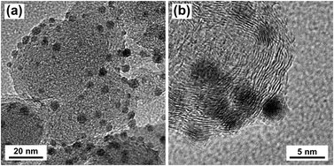
Silver nanoparticles (Ag NPs) were synthesized by reducing silver nitrate in oleylamine and oleic acid according to literature.35 Ag/C was prepared by depositing Ag NPs onto Vulcan XC-72R carbon black (CB). Transmission electron microscopy (TEM) images of the Ag/C catalyst are shown in Fig. 1. The particle size histogram (ESI, Fig. S5†) showed that deposited Ag NPs ranged from approximately 2.0 to 6.0 nm with a mean particle diameter of 3.9 nm. X-ray diffraction (XRD) showed that the Ag NPs were crystalline with a face-centered cubic (fcc) structure, and average crystallite size of approximately 2.3 nm (ESI, Fig. S6†). XPS analysis of the Ag/C catalyst showed characteristic binding energy peaks for Ag3d5/2 (368.2 eV) and Ag3d3/2 (374.2 eV), indicating Ag NPs were in the metallic Ag0 state (ESI, Fig. S7†). Raman spectra of the Ag/C catalyst was consistent with the spectra of Vulcan XC-72R carbon black (ESI, Fig. S8†). The Ag loading on the CB support was estimated by thermal gravimetric analysis (TGA) to be 9.1% (ESI, Fig. S9†).2.2 Electrochemical reduction of HMF
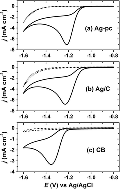
The Ag/C catalyst was initially evaluated for HMF reduction in a borate buffer (pH 9.2) electrolyte by cyclic voltammetry. All potentials herein are reported with respect to a Ag/AgCl reference electrode. Working electrodes were prepared by drop-casting an ink dispersion of Ag/C onto a glassy carbon disk electrode. Additionally, CB-modified glassy carbon and polycrystalline silver (Ag-pc) disk electrodes were tested for comparison. The electrochemically-active surface area (ECSA) for Ag was determined by oxidative stripping voltammetry of under-potential deposited lead (PbUPD).36 The amount of Ag/C drop-cast onto the glassy carbon electrode was chosen to give similar Ag ECSA as the Ag-pc disk electrode (details in section 4.5).Cyclic voltammetry revealed that Ag/C, Ag-pc, and CB electrodes were active for HMF reduction (Fig. 2). The onset potentials for HMF reduction were −1.03 V, −1.05 V, and −1.21 V for Ag/C, Ag-pc, and CB, respectively, as defined herein as the potential at which background-corrected current density reached −0.1 mA cm−2. This suggests that the CB support material present in Ag/C may participate in HMF reduction at potentials more negative than −1.21 V. The peak currents densities for Ag/C and Ag-pc (−6.8 and −7.0 mA cm−2, respectively) were approximately two-fold higher than for CB (−3.3 mA cm−2). Koutecký–Levich analysis of the reduction waves indicated that the electron transfer number (n) with respect to HMF was approximately two for Ag-pc and Ag/C and one for CB (ESI, Fig. S10†). This indicates that different HMF reduction mechanisms may be operable for Ag-based electrodes than for CB electrodes. Fig. 2 also shows voltammograms measured in electrolytes without HMF, for which the reduction waves can be assigned to the hydrogen evolution reaction (HER). The HER current was negligible at potentials close to the onset of HMF reduction, but increased substantially at potentials more negative than about −1.4 V. This corresponds to the potential range at which a second reduction wave initiated for electrolytes containing HMF, suggesting that HMF reduction and HER may proceed concurrently at very negative potentials. The second reduction wave was less notable for CB, reflecting the lower HER activity for CB compared to Ag-based electrodes.
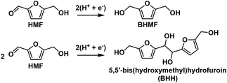
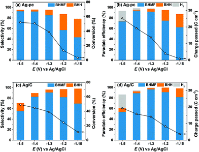
HMF reduction was studied using potential-controlled electrolysis over the range of −1.15 V to −1.5 V. Electrodes were prepared by drop-casting an ink dispersion of Ag/C onto a carbon paper substrate. The amount of Ag/C loaded onto the carbon paper was chosen to give similar Ag ECSA as the Ag-pc electrode, as determined by PbUPD stripping voltammetry (details in section 4.8). HMF reduction products for Ag/C and Ag-pc were evaluated in terms of selectivity and faradaic efficiency. The main HMF reduction products were BHMF from hydrogenation and BHH (5,5′-bis(hydroxymethyl)hydrofuroin) from hydrodimerization (Scheme 2). The product distribution was highly dependent on the cathode potential (Fig. 3). BHMF selectivity increased and BHH decreased with more negative potentials over the range of −1.15 V to −1.3 V. BHMF selectivity was notably higher for Ag/C than Ag-pc over this potential range; however, it decreased at more negative potentials for Ag/C, corresponding to increased formation of BHH and unidentified products. In contrast, BHMF selectivity continued to rise with more negative potentials for Ag-pc. Although, HER was active at those potentials and the faradaic efficiency for BHMF was lower (e.g. 73.7% at −1.5 V for Ag-pc). As a result, the optimal BHMF generation in terms of faradaic efficiency was obtained using Ag/C at −1.3 V, for which BHMF efficiency reached 96.2%. Stability tests were conducted by reusing one Ag/C electrode for four consecutive trials. HMF conversion rate and BHMF efficiency decreased slightly after the first trial but remained stable for the remaining trials (ESI, Fig. S11†). The initial drop in performance may be due to Ag particle agglomeration; larger Ag NPs were observed by TEM following the stability test (ESI, Fig. S12†). The ICP-AES analysis of the electrolyte solution showed that Ag leaching was negligible (i.e. less than detection limit of 0.6 ppb Ag in electrolyte) after two hours of HMF reduction.
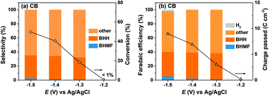
HMF reduction was conducted using CB-modified carbon paper electrodes to decouple the contributions of Ag NPs and the CB support material to the observed product selectivities for Ag/C. HMF reduction products were detected at −1.2 V for CB electrodes, however HMF conversion was insufficient (i.e. <1%) for quantitative product analysis. Fig. 4 shows that HMF conversion rates were enhanced at more negative potentials and reached 50% at −1.5 V, which is comparable to the values for Ag/C and Ag-pc (i.e., 49% and 52%, respectively at −1.5 V). In sharp contrast to Ag-based electrodes, BHH was the major detected product for CB electrodes, and very little BHMF was generated (i.e. <3% selectivity). Also, HER was a minor contribution to the total charge passed (i.e. ∼2% faradaic efficiency at −1.5 V), reflecting the poor HER activity of CB.
The combined selectivities for BHH and BHMF were low (i.e. 32–35%), indicating that other products were generated from HMF reduction with CB electrodes. We detected several unknown products in the HPLC chromatographs and 1H NMR spectra, which were not identified or quantified in this work. As previously discussed, the Koutecký–Levich analysis indicated that HMF reduction on CB electrodes proceeds mainly by a one-electron transfer process. Therefore, we hypothesize that the unidentified species are dimer or oligomer byproducts of HMF hydrodimerization reactions, which consume one electron per HMF, rather than products of hydrogenation or hydrogenolysis reactions as suggested in an earlier report.37 These results show that CB electrodes were active for HMF reduction and generated substantial amounts of BHH and unidentified products starting around −1.3 V. On this basis, we attribute the lower BHMF and total selectivities for Ag/C compared to Ag-pc at −1.4 V and −1.5 V (Fig. 3) to the activity of the CB support material present in Ag/C.
Regarding the mechanism of HMF hydrogenation to BHMF in basic or neutral media, there is uncertainty whether the hydrogen source is water or surface adsorbed hydrogen (H*),11,13,29,37 as depicted in eqn (1) and (2), respectively.
| HMF + 2H2O + 2e− → BHMF + 2OH− | (1) |
| HMF + 2H* → BHMF | (2) |
The latter pathway is known as electrocatalytic hydrogenation (ECH).17 The electrochemical formation of H* (i.e. Volmer step) occurs by water reduction in basic or neutral media (eqn (3)),38 in which * designates a surface site.
| H2O + * + e− → H* + OH− | (3) |
ECH reactions involve strong interactions between the electrode surface and reactants, and are therefore highly dependent on the nature of the electrode material.39 Kwon et al. hypothesized that HMF hydrogenation to BHMF in neutral media occurs directly by water molecules (eqn (1)) on the basis of the nearly identical onset potentials observed for a wide range of metallic electrodes.37 On the other hand, Roylance et al. studied HMF reduction on Ag-based electrodes in basic media (i.e. pH 9.2) and reported that H* was likely involved in BHMF formation within the potential region where HER, and therefore H* formation, were possible.13 Our viewpoint is that ECH was the major BHMF generation pathway for Ag-based electrodes under the conditions reported herein. This is self-consistent with the low BHMF selectivity we report for CB electrodes (Fig. 4), as carbon is known to have very weak H* adsorption,40 and is therefore not expected to facilitate ECH reactions. However, it should be noted that BHMF was a major product for Ag/C and Ag-pc electrodes even within the potential region where HER current was negligible (i.e. −1.15 V ≥ E ≥ −1.3 V). A recent density functional theory (DFT) study of Ag cathodes indicated that the lowest energy pathway for HER via water reduction is the Volmer–Heyrovsky sequence, and the Heyrovsky step is rate-limiting.41 Therefore, it is very plausible that HMF hydrogenation by H* (i.e. ECH) can proceed within a potential region where the Volmer step is facile but HER is kinetically-limited by the Heyrovsky step.
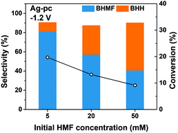
We found that the selectivity of HMF reduction to BHMF or BHH was dependent on the cathode potential for Ag-based electrodes; BHMF selectivity increased at more negative potentials down to −1.3 V for Ag/C and −1.5 V for Ag-pc (Fig. 3). The electrochemical Volmer step (eqn (3)) is accelerated at more negative potentials, so one explanation for the selectivity trend is that BHMF formation was promoted by higher H* availability. Additional experiments were performed with different initial HMF concentrations to gain more insight regarding BHMF and BHH selectivity. Ag-pc electrodes were used instead of Ag/C to avoid contributions of the CB support material to the observed product selectivity. Fig. 5 shows that BHMF selectivity at −1.2 V decreased from 81% to 41% when the HMF concentration was increased from 5.0 mM to 50 mM. It is likely that higher concentrations led to increased surface coverage of HMF, and that BHMF formation via ECH was less favorable due to insufficient availability of H* relative to adsorbed HMF. Accordingly, another reasonable explanation for the higher BHMF selectivity observed at more negative potentials (Fig. 3) would be that higher degrees of HMF conversion were achieved at those potentials, and therefore lower bulk HMF concentrations were present. However, we conducted an extended electrolysis at −1.2 V and found that BHMF selectivity (56%) was still notably lower than at −1.3 V (i.e. 85%), even though similar HMF conversion was reached (ESI, Table S1†).
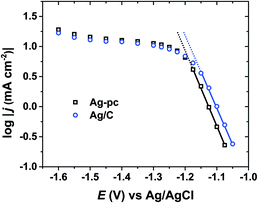
As a heterogeneous process, electrochemical HMF reduction may be subject to external mass-transport limitations. In this way, the HMF concentration at the electrode surface may be significantly lower than in the bulk electrolyte, which could impact the selectivity of HMF reduction. Quasi-steady-state current densities were measured over a wide potential range using conditions (i.e., reactor geometry, electrode size, stirring rate) identical to electrolysis experiments. Fig. 6 shows the logarithm of current density versus potential (log(j) vs. E) for Ag/C and Ag-pc. For both electrodes, Tafel-like behaviour (i.e. linear log(j) vs. E relationship) was observed within the potential range of approximately −1.05 to −1.15 V, indicating that HMF reduction rate was limited by charge-transfer kinetics.42 Within this potential region, HMF reduction currents were 2–3 times higher on Ag/C than Ag-pc, even though the Ag ECSA values were very similar (i.e. 2.52 cm2 and 2.51 cm2 for Ag/C and Ag-pc, respectively). This suggests that Ag/C may have intrinsically higher catalytic activity for HMF reduction than bulk, polycrystalline Ag; however, definitive elucidation of nanoscale or particle size effects is beyond the scope of this work. At potentials more negative than about −1.15 V, the plots of log(j) vs. E (Fig. 6) for both electrodes deviated from Tafel-like behavior, indicative of mass-transport control. Almost completely mass-transport-limited behavior (i.e. a current “plateau”) was observed from about −1.30 V to −1.50 V, which corresponds to the optimal potential range for BHMF formation (Fig. 3). We previously showed that BHMF was favored at low HMF concentrations (Fig. 5), so we hypothesize that the higher BHMF selectivity observed at more negative potentials was at least partially derived from lower local HMF concentrations at the electrode surface resulting from mass-transport limitations. In the same way, the enhanced BHMF selectivity for Ag/C compared to Ag-pc at mild potentials (i.e. −1.15 V and −1.2 V, Fig. 3) may be due to the higher current densities for Ag/C compared to Ag-pc, which would result in more significant mass-transport limitations and lower local HMF concentrations.
2.3 ACT-mediated HMF oxidation
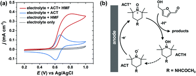
In electrochemical cells, the two electrodes are constrained to have equal, but opposite, current flow. As a result, a major challenge of conducting paired electrolysis is that the operating potentials for the two half-reactions cannot be independently controlled via the external circuit. We found that the selectivity and efficiency of Ag-catalyzed HMF hydrogenation were very sensitive to the cathode potential (Fig. 3). Therefore, in order to successfully pair HMF oxidation to FDCA and hydrogenation to BHMF in a single cell, it is necessary to find a method to facilitate selective oxidation of HMF that is insensitive to anode potential. Unfortunately, it has been shown that the selectivity of electrocatalytic HMF oxidation on carbon-supported metal catalysts is highly dependent on anode potential.43An alternative approach is to use a homogeneous electrocatalyst to facilitate indirect electrochemical HMF oxidation.32 Organic nitroxyl radical catalysts, such as TEMPO and its derivatives, are widely used for selective oxidation of alcohols.44,45 In particular, 4-acetamido-TEMPO (ACT) has been identified as a very promising homogeneous electrocatalyst for alcohol oxidation, owing to its superior activity and lower cost compared to other TEMPO derivitatives.46Fig. 7a shows the cyclic voltammogram for ACT with a glassy carbon electrode in borate buffer electrolyte (pH 9.2). ACT exhibited reversible one-electron oxidation/reduction waves; ACT was oxidized to an oxoammonium cation (ACT+) on the anodic sweep and subsequently reduced back to a nitroxyl radical on the cathodic sweep. After addition of HMF to the ACT-containing electrolyte, the anodic current was increased. This is attributed to the regeneration of ACT following the reaction between HMF and ACT+ (Fig. 7b). The regeneration of ACT may occur either by the reoxidation of the ACT hydroxylamine (ACTH) or by the comproportionation of ACT+ and ACTH.47 The cathodic wave disappeared in the presence of HMF because ACT+ was consumed during the HMF oxidation reaction, and therefore not present to be electrochemically reduced. No HMF oxidation current was observed in electrolyte without ACT, demonstrating that non-mediated HMF oxidation was not operable under these conditions.
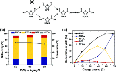
ACT-mediated HMF oxidation was conducted in an H-type cell using a carbon felt anode. In this system, HMF is oxidized through the non-electrochemical reaction with ACT+ in solution; therefore, HMF product selectivity is not directly dependent on the anode potential. Fig. 8a shows that HMF oxidation can proceed by two pathways, both leading to FDCA. Accordingly, the selectivity of ACT-mediated HMF oxidation to FDCA is mainly determined by the overall extent of reaction. This was demonstrated by performing the reaction at three different anode potentials while controlling the total amount of charge passed for each experiment to obtain the same extent of reaction (i.e. ∼50%). In this way, HMF oxidation product distribution was largely unaffected as anode potential was varied between 0.7 V and 0.9 V (Fig. 8b). High HMF conversion and selectivity to FDCA was achieved after ACT-mediated HMF oxidation at 0.7 V was run to completion (i.e. 72.2 C of charge passed), as shown in Fig. 8c. The apparent reaction sequence was HMF → 2,5-diformylfuran (DFF) → 5-formyl-2-furoic acid (FFCA) → FDCA. The final yield and faradaic efficiency for FDCA were about 97% and 98%, respectively.
2.4 Paired HMF hydrogenation and oxidation
Simultaneous conversion of HMF to BHMF and FDCA was achieved in a paired electrochemical cell. The cathode potential was controlled at −1.3 V to minimize undesired hydrodimerization and hydrogen evolution reactions at the Ag/C electrode. ACT-mediated HMF oxidation at the anode effectively served as the counter reaction, as its potential was not controlled. The cathode and anode electrolytes were separated by an anion-exchange membrane. The initial amount of HMF in the cathode electrolyte was three times greater than for the anode, accounting for the stoichiometry shown in eqn (4)–(6).| Cathode: HMF + 2H2O + 2e− → BHMF + 2OH− | (4) |
| Anode: HMF + 6OH− → FDCA + 6e− + 4H2O | (5) |
| Overall: 4HMF + 2H2O → 3BHMF + FDCA | (6) |
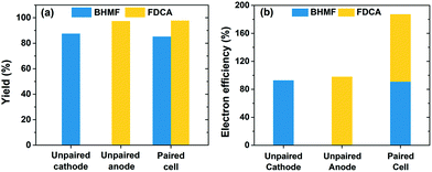
Fig. 9a shows that the individual yields for BHMF and FDCA reached 85% and 98%, respectively, after 72.2 C of charge was passed in the paired cell. The yields were very similar to those achieved in separate (i.e. unpaired) cells, which are also shown in Fig. 9a. These results show that the two HMF half-reactions were compatible and proceeded without severe complications or adverse effects when paired in a single cell. A key feature of the paired electrolysis is that each transferred electron participates in the generation of two desired products (i.e. BHMF and FDCA). Accordingly, the combined electron efficiency to BHMF and FDCA was 187% for the paired cell, a nearly two-fold enhancement compared to the unpaired cells (Fig. 9b). This is one of the first demonstrations of paired HMF electrolysis and to the best of our knowledge is the highest reported combined electron efficiency for HMF conversion (ESI, Table S2†).
3. Conclusions
This work demonstrated that HMF can be efficiently converted to two important biobased polymer precursors, BHMF and FDCA, in a paired electrochemical cell. Electrocatalytic hydrogenation of HMF to BHMF was achieved using self-prepared Ag/C as the cathode catalyst. The selectivity and efficiency for BHMF formation were dependent on cathode potential and bulk HMF concentration. We also showed that the carbon support material in Ag/C was active for HMF reduction at cathodic potentials more negative than about −1.2 V, leading to hydrodimerization to BHH and low BHMF selectivity. A key feature of this work was the application of ACT as a homogeneous electrocatalyst to facilitate indirect HMF oxidation at the anode. The selectivity of ACT-mediated HMF oxidation was not dependent on anode potential, which enabled us to successfully pair HMF hydrogenation and oxidation half-reactions in a single divided cell operated under cathode potential control. Electrocatalytic HMF conversion in the paired cell achieved high yields for BHMF and FDCA (85% and 98%, respectively) and a combined electron efficiency of 187%, corresponding to a nearly two-fold enhancement compared to the unpaired cells. This approach shows the potential benefits of using paired electrochemical cells for the sustainable production of chemicals.4. Experimental
4.1 Chemicals and materials
Sodium hydroxide (97%), 4-acetamido-TEMPO (ACT, 98%), oleylamine (70%), oleic acid (90%), 5-(hydroxymethyl)furfural (HMF, 99%), 2,5-furandicarboxylic acid (FDCA, 97%), 5-hydroxymethyl-2-furancarboxylic acid (HFCA), and 2,5-diformylfuran (DFF, 97%) were purchased from Sigma Aldrich. Acetone (99.8%), hexanes (99.9%), 2-propanol (99.9%), boric acid (100%) and buffer standard solutions (pH 7.0 and 10.0) were purchased from Fisher Scientific. Silver(I) nitrate (99.5%) and lead(II) nitrate (99%) were purchased from Acros Organics. 2,5-Bis(hydroxymethyl)furan (98%) was purchased from Ark Pharm, Inc. 5-Formyl-2-furoic acid (FFCA, 99%) was purchased from TCI. Silver foil (99.998%, 0.1 mm thickness) and carbon felt (99.0%, 3.18 mm thickness) were obtained from Alfa Aesar. Deionized water (18.2 MΩ cm) obtained from a Barnstead E-Pure™ purification system was used to prepare all electrolytes.4.2 Catalyst synthesis
Ag nanoparticles (Ag NPs) were synthesized using a procedure adapted from literature.35 Briefly, silver nitrate (1.5 mmol) was dissolved in oleylamine (30 mL) and oleic acid (1.0 mL). The solution was stirred at 350 rpm with a magnetic stir bar and kept under nitrogen atmosphere. The solution was heated to 60 °C and held for 5 minutes to ensure the silver precursor was completely dissolved. The solution temperature was then ramped to 120 °C and held for 2 hours. The solution was cooled to approximately 25 °C and 30 mL of acetone was added. Then, the solution was divided into six tubes and additional acetone (25 mL) was added to each tube. The mixtures were centrifuged for 8 minutes at 8500 rpm and then the liquid was decanted. The Ag NPs were washed two more times with acetone by centrifugation (8 minutes at 8500 rpm). Ag/C was prepared by depositing Ag NPs onto carbon black (Vulcan XC-72R, Cabot). Separately, Ag NPs were re-dispersed in hexane (8.0 mg mL−1) and carbon black was dispersed in a 1![[thin space (1/6-em)]](https://www.rsc.org/images/entities/char_2009.gif) :
:![[thin space (1/6-em)]](https://www.rsc.org/images/entities/char_2009.gif) 1 hexane/acetone solution (1.0 mg mL−1). For a typical synthesis, 2.0 mL of the Ag NPs dispersion was added drop-wise into 64.0 mL of carbon black dispersion under ultrasonication. The mixture was kept under ultrasonication for 1 hour. Finally, the Ag/C catalyst was recovered by vacuum filtration and dried overnight in a vacuum oven at 30 °C.
1 hexane/acetone solution (1.0 mg mL−1). For a typical synthesis, 2.0 mL of the Ag NPs dispersion was added drop-wise into 64.0 mL of carbon black dispersion under ultrasonication. The mixture was kept under ultrasonication for 1 hour. Finally, the Ag/C catalyst was recovered by vacuum filtration and dried overnight in a vacuum oven at 30 °C.
4.3 Catalyst characterizations
X-ray diffraction (XRD) patterns were collected with a Rigaku Ultima IV system operated with a Cu Kα source (λ = 1.5406 Å) at 40 kV and 44 mA and equipped with a diffracted beam monochromator (carbon). The average crystal size was estimated from the Ag (220) diffraction peak according to the Scherrer equation,48 as shown in eqn (7): | (7) |
4.4 Electrochemical measurements
Electrochemical tests were performed with a BioLogic SP-300 electrochemical workstation. The reference electrode was a single-junction Ag/AgCl (Pine Research Instrumentation) for all experiments. Solution resistance was determined by potentiostatic electrochemical impedance spectroscopy and compensated at 90% by the electrochemical workstation. All current density values are reported with respect to geometric surface area. The electrolyte was a sodium borate buffer (0.5 M) prepared from boric acid and sodium hydroxide, adjusted to pH 9.2, as measured by a pH probe (Hanna HI98103).4.5 Cyclic voltammetry and Koutecký–Levich analysis
Cyclic voltammetry (CV) for HMF reduction was performed for a polycrystalline silver (Ag-pc) disk electrode (5.0 mm diameter, Pine Research Instrumentation) and for glassy carbon disk electrodes (GCE, 5.0 mm diameter, Pine Research Instrumentation) modified with Ag/C or carbon black (CB). CVs for ACT-mediated HMF oxidation were performed on a bare GCE. Before use, the disk electrodes were polished with an alumina suspension (0.3 μm, Allied High Tech Products, Inc.) on a microcloth polishing disk (Buehler) and cleaned with deionized water in an ultrasonic bath. Ink was prepared by dispersing Ag/C or CB in a solution of isopropanol and deionized water (1![[thin space (1/6-em)]](https://www.rsc.org/images/entities/char_2009.gif) :
:![[thin space (1/6-em)]](https://www.rsc.org/images/entities/char_2009.gif) 1 v/v) at a concentration of 1.0 mg mL−1. Nafion solution (5% w/w, Ion Power) was added to the ink to achieve a Nafion loading of 10% w/w in the dry catalyst film. The ink dispersion was mixed ultrasonically and then drop-cast on the GCE. The volume of Ag/C ink drop-cast onto the GCE was 8.0 μL, which was chosen to give similar Ag electrochemically-active surface area (ECSA) as the Ag-pc disk electrode. Details of Ag ECSA determination are included in section 4.9. The volume of CB ink drop-cast onto the GCE was 6.4 μL. The counter electrode was a platinum coil, separated from the main electrolyte with a fritted glass tube. The electrochemical cell was purged with nitrogen gas before and during measurements. Cyclic voltammograms were collected with a 50 mV s−1 sweep rate.
1 v/v) at a concentration of 1.0 mg mL−1. Nafion solution (5% w/w, Ion Power) was added to the ink to achieve a Nafion loading of 10% w/w in the dry catalyst film. The ink dispersion was mixed ultrasonically and then drop-cast on the GCE. The volume of Ag/C ink drop-cast onto the GCE was 8.0 μL, which was chosen to give similar Ag electrochemically-active surface area (ECSA) as the Ag-pc disk electrode. Details of Ag ECSA determination are included in section 4.9. The volume of CB ink drop-cast onto the GCE was 6.4 μL. The counter electrode was a platinum coil, separated from the main electrolyte with a fritted glass tube. The electrochemical cell was purged with nitrogen gas before and during measurements. Cyclic voltammograms were collected with a 50 mV s−1 sweep rate.
Linear sweep voltammograms for HMF reduction were collected at various electrode rotation rates (ω, RPM) using a modulated speed rotator (Pine Research Instrumentation) for Koutecký–Levich analysis. Koutecký–Levich plots (1/j versus ω−0.5) were constructed using the background-corrected current density values at −1.5 V. The electron transfer number for HMF reduction, n, was extracted from the slope of the Koutecký–Levich plot, defined by eqn (8):
| Slope = (0.201nFD2/3υ−1/6C)−1 | (8) |
![[thin space (1/6-em)]](https://www.rsc.org/images/entities/char_2009.gif) 485.3 C mol−1), D is the diffusion coefficient of HMF in water (9.169 × 10⁻⁶ cm2 s−1),50υ is the kinematic viscosity of water (0.01 cm2 s−1), and C is the HMF concentration (20.0 mM).
485.3 C mol−1), D is the diffusion coefficient of HMF in water (9.169 × 10⁻⁶ cm2 s−1),50υ is the kinematic viscosity of water (0.01 cm2 s−1), and C is the HMF concentration (20.0 mM).
4.6 Electrolysis of HMF
Electrocatalytic hydrogenation was performed in an H-type cell. Anode and cathode chambers were separated with an anion-exchange membrane (Tokuyama Corp., A201). The cathode electrolyte was purged with argon gas (99.999%, Airgas, Inc.) throughout the reaction to remove dissolved O2 and evolved H2. Electrolysis was conducted using 20.0 mL of electrolyte containing HMF (typically 20.0 mM) in the cathode. The cathode electrolyte was stirred with a PTFE-coated magnetic bar (size: 7/8′′ × 3/16′′) at 500 rpm. A graphite rod counter electrode was used as the anode.ACT-mediated HMF oxidation was performed in an H-type cell with a similar configuration. The anode electrode was carbon felt with dimensions of 1.5 cm by 1.0 cm exposed to the electrolyte. Ag-pc served as the counter electrode to facilitate the hydrogen evolution reaction. Carbon felt electrodes were washed with acetonitrile to remove organic residues and then rinsed with deionized water before each use. Unless noted otherwise, the anode electrolyte volume was 12.5 mL and contained 10.0 mM HMF and 1.0 mM ACT. The anode electrolyte was purged with argon gas (99.999%, Airgas, Inc.) throughout the reaction, and was stirred with a small PTFE-coated stir bar at 500 rpm.
The paired HMF electrolysis was performed in an H-type cell that combined the cathode configuration previously described for HMF hydrogenation and the anode configuration described for HMF oxidation. The paired cell was operated by controlling the cathode potential to be −1.3 V.
4.7 Quasi-steady-state current measurements
Quasi-steady-state current densities were measured by staircase voltammetry in an H-type cell (pH 9.2, 20.0 mM HMF). Each potential step was held for 15 seconds and the mean current measured over the last 10 seconds of each step was reported.4.8 Electrode preparation for electrolysis
Ag foil served as the Ag-pc electrode for electrolysis following a cleaning sequence of isopropanol, DI water, 0.5 M hydrochloric acid and DI water. The Ag foil was masked off to expose a 1 cm by 1 cm region, giving a geometric area of 2 cm2 after accounting for the front and back sides. The Ag/C and CB electrodes for electrolysis were prepared by drop-casting ink dispersions onto carbon paper. The carbon paper electrodes were masked off to a geometric area of 2 cm2 in the same manner as the Ag foil. Ink was prepared by dispersing Ag/C or CB in a solution of isopropanol and deionized water (9![[thin space (1/6-em)]](https://www.rsc.org/images/entities/char_2009.gif) :
:![[thin space (1/6-em)]](https://www.rsc.org/images/entities/char_2009.gif) 1 v/v) at a concentration of 1.0 mg mL−1. Nafion (5% w/w, Ion Power) was added to the ink with a target loading with a catalyst to Nafion ratio of 9
1 v/v) at a concentration of 1.0 mg mL−1. Nafion (5% w/w, Ion Power) was added to the ink with a target loading with a catalyst to Nafion ratio of 9![[thin space (1/6-em)]](https://www.rsc.org/images/entities/char_2009.gif) :
:![[thin space (1/6-em)]](https://www.rsc.org/images/entities/char_2009.gif) 1 w/w. The ink dispersion was sonicated for 3 minutes immediately before being drop-cast. The volume of Ag/C ink drop-cast onto carbon paper was 129.6 μL, which was chosen to give similar Ag ECSA as the Ag-pc electrode (ESI, Fig. S13 and 14†).
1 w/w. The ink dispersion was sonicated for 3 minutes immediately before being drop-cast. The volume of Ag/C ink drop-cast onto carbon paper was 129.6 μL, which was chosen to give similar Ag ECSA as the Ag-pc electrode (ESI, Fig. S13 and 14†).
4.9 Determination of Ag ECSA
Stripping voltammetry of PbUPD was performed for Ag-pc and Ag/C electrodes to estimate the Ag ECSA. The electrolyte was 0.5 M borate buffer solution containing 125 μM lead nitrate. The electrolyte was purged with nitrogen before and during experiments. For Ag/C, Pb UPD was conducted by holding −0.55 V for 2 min. The PbUPD stripping voltammogram was collected immediately after deposition by sweeping from the deposition potential to 0.0 V at 20 mV s−1. The same procedure was used for Ag-pc, except the deposition potential was changed to −0.5 V to avoid bulk Pb deposition. The Ag ECSA was determined using eqn (9): | (9) |
4.10 Product analysis
HMF hydrogenation and oxidation products were analyzed by high-performance liquid chromatography (HPLC). Evolved H2 gas was quantified with a gas chromatography connected to the outlet of the cathode chamber. BHH was identified by 1H NMR and HSQC and quantified by HPLC. Two isomers of BHH are reported together for simplicity. Details of product analysis and calculations for selectivity, faradaic efficiency, and combined electron efficiency are provided in the ESI.†Conflicts of interest
The authors claim no conflicts of interest.Acknowledgements
This research was funded by NSF-CBET 1512126 and Bailey Research Career Development Award. W. L. acknowledges the Iowa State University Start-Up Fund, Ames Laboratory Start-Up Fund, Iowa Energy Center, and Richard Seagrave Professorship; and is grateful to Ting-Han Lee, Hengzhou Liu, Prof. J. P. Tessonnier, and Prof. Eric Cochran from Iowa State University for fruitful discussions. We are grateful to Dr Tao Ma from the Sensitive Instrument Facility at Department of Energy Ames Laboratory, Dr Yang Qiu, and Yifu Chen for assistance with TEM. We thank Prof. Emily Smith and Jingzhe Li of Iowa State University for collecting Raman spectra. We appreciate Dr Patrick Johnston, Dr Dapeng Jing, and Dr Scott Schlorholtz from Iowa State University for conducting ICP-OES, XPS and TGA measurements, respectively.References
- B. A. Frontana-Uribe, R. D. Little, J. G. Ibanez, A. Palma and R. Vasquez-Medrano, Green Chem., 2010, 12, 2099–2119 RSC.
- E. J. Horn, B. R. Rosen and P. S. Baran, ACS Cent. Sci., 2016, 2, 302–308 CrossRef CAS PubMed.
- M. J. Janik, S. A. Wasileski, C. D. Taylor and M. Neurock, in Fuel Cell Catalysis, ed. M. T. M. Koper, John Wiley & Sons, Inc., Hoboken, New Jersey, 2009, ch. 4, pp. 93–128 Search PubMed.
- L. Xin, Z. Zhang, J. Qi, D. Chadderdon and W. Li, Appl. Catal., B, 2012, 125, 85–94 CrossRef CAS.
- Z. Zhang, L. Xin, J. Qi, D. J. Chadderdon, K. Sun, K. M. Warsko and W. Li, Appl. Catal., B, 2014, 147, 871–878 CrossRef CAS.
- B. H. Nguyen, R. J. Perkins, J. A. Smith and K. D. Moeller, Beilstein J. Org. Chem., 2015, 11, 280–287 CrossRef CAS PubMed.
- B. H. Nguyen, A. Redden and K. D. Moeller, Green Chem., 2014, 16, 69–72 RSC.
- F. Harnisch and C. Urban, Angew. Chem., Int. Ed., 2018, 57, 10016–10023 CrossRef CAS.
- D. S. P. Cardoso, B. Šljukić, D. M. F. Santos and C. A. C. Sequeira, Org. Process Res. Dev., 2017, 21, 1213–1226 CrossRef CAS.
- Y. Kwon, E. de Jong, S. Raoufmoghaddam and M. T. M. Koper, ChemSusChem, 2013, 6, 1659–1667 CrossRef CAS.
- Y. Kwon, Y. Y. Birdja, S. Raoufmoghaddam and M. T. M. Koper, ChemSusChem, 2015, 8, 1745–1751 CrossRef CAS PubMed.
- F. J. Holzhäuser, J. Artz, S. Palkovits, D. Kreyenschulte, J. Büchs and R. Palkovits, Green Chem., 2017, 19, 2390–2397 RSC.
- J. J. Roylance, T. W. Kim and K.-S. Choi, ACS Catal., 2016, 6, 1840–1847 CrossRef CAS.
- X. H. Chadderdon, D. J. Chadderdon, J. E. Matthiesen, Y. Qiu, J. M. Carraher, J. P. Tessonnier and W. Li, J. Am. Chem. Soc., 2017, 139, 14120–14128 CrossRef CAS PubMed.
- M. Suastegui, J. E. Matthiesen, J. M. Carraher, N. Hernandez, N. R. Quiroz, A. Okerlund, E. W. Cochran, Z. Shao and J.-P. Tessonnier, Angew. Chem., Int. Ed., 2016, 55, 2368–2373 CrossRef CAS PubMed.
- U. Sanyal, J. Lopez-Ruiz, A. B. Padmaperuma, J. Holladay and O. Y. Gutiérrez, Org. Process Res. Dev., 2018, 22, 1590–1598 CrossRef CAS.
- J. Lessard, in Organic Electrochemistry, ed. O. Hammerich and B. Speiser, CRC Press, Boca Raton, FL, 5th edn, 2015, pp. 1658–1664 Search PubMed.
- P. Nilges and U. Schröder, Energy Environ. Sci., 2013, 6, 2925–2931 RSC.
- J. G. Ibanez, B. A. Frontana-Uribe and R. Vasquez-Medrano, J. Mex. Chem. Soc., 2016, 60, 247–260 CAS.
- M. Tahir, L. Pan, F. Idrees, X. Zhang, L. Wang, J.-J. Zou and Z. L. Wang, Nano Energy, 2017, 37, 136–157 CrossRef CAS.
- M. J. Llorente, B. H. Nguyen, C. P. Kubiak and K. D. Moeller, J. Am. Chem. Soc., 2016, 138, 15110–15113 CrossRef CAS PubMed.
- R. S. Sherbo, R. S. Delima, V. A. Chiykowski, B. P. MacLeod and C. P. Berlinguette, Nat. Catal., 2018, 1, 501–507 CrossRef CAS.
- P. Zhang, X. Sheng, X. Chen, Z. Fang, J. Jiang, M. Wang, F. Li, L. Fan, Y. Ren, B. Zhang, B. J. J. Timmer, M. S. G. Ahlquist and L. Sun, Angew. Chem., Int. Ed., 2019, 58, 9155–9159 CrossRef CAS.
- G. Chamoulaud, D. Floner, C. Moinet, C. Lamy and E. M. Belgsir, Electrochim. Acta, 2001, 46, 2757–2760 CrossRef CAS.
- R. A. Sheldon, Green Chem., 2014, 16, 950–963 RSC.
- J. N. Chheda, Y. Roman-Leshkov and J. A. Dumesic, Green Chem., 2007, 9, 342–350 RSC.
- J. M. R. Gallo, D. M. Alonso, M. A. Mellmer and J. A. Dumesic, Green Chem., 2013, 15, 85–90 RSC.
- Y. Jiang, X. Wang, Q. Cao, L. Dong, J. Guan and X. Mu, in Sustainable Production of Bulk Chemicals, ed. M. Xian, Springer, 2016 Search PubMed.
- Y. Kwon, K. J. P. Schouten, J. C. van der Waal, E. de Jong and M. T. M. Koper, ACS Catal., 2016, 6, 6704–6717 CrossRef CAS.
- C. Moreaua, M. N. Belgacemb and A. Gandini, Top. Catal., 2004, 27, 11–30 CrossRef.
- A. Gandini, A. J. D. Silvestre, C. P. Neto, A. F. Sousa and M. Gomes, J. Polym. Sci., Part A: Polym. Chem., 2009, 47, 295–298 CrossRef CAS.
- H. G. Cha and K.-S. Choi, Nat. Chem., 2015, 7, 328–333 CrossRef CAS.
- X. H. Chadderdon, PhD thesis, Iowa State University, 2018 Search PubMed.
- S. Li, X. Sun, Z. Yao, X. Zhong, Y. Cao, Y. Liang, Z. Wei, S. Deng, G. Zhuang, X. Li and J. Wang, Adv. Funct. Mater., 2019, 1904780 CrossRef CAS.
- S. Peng, J. M. McMahon, G. C. Schatz, S. K. Gray and Y. Sun, Proc. Natl. Acad. Sci. U. S. A., 2010, 107, 14530–14534 CrossRef CAS PubMed.
- E. Kirowa-Eisner, Y. Bonfil, D. Tzur and E. Gileadi, J. Electroanal. Chem., 2003, 552, 171–183 CrossRef CAS.
- Y. Kwon, E. d. Jong, S. Raoufmoghaddam and M. T. M. Koper, ChemSusChem, 2013, 6, 1659–1667 CrossRef CAS PubMed.
- B. E. Conway and B. V. Tilak, Electrochim. Acta, 2002, 47, 3571–3594 CrossRef CAS.
- A. J. Bard, J. Am. Chem. Soc., 2010, 132, 7559–7567 CrossRef CAS PubMed.
- Y. Zheng, Y. Jiao, L. H. Li, T. Xing, Y. Chen, M. Jaroniec and S. Z. Qiao, ACS Nano, 2014, 5, 5290–5296 CrossRef PubMed.
- M. R. Singh, J. D. Goodpaster, A. Z. Weber, M. Head-Gordon and A. T. Bell, Proc. Natl. Acad. Sci. U. S. A., 2017, 114, E8812–E8821 CrossRef CAS PubMed.
- A. J. Bard and L. R. Faulkner, Electrochemical Methods: Fundamentals and Applications, John Wiley & Sons, Inc., New York, 2nd edn, 2001 Search PubMed.
- D. J. Chadderdon, L. Xin, J. Qi, Y. Qiu, P. Krishna, K. L. More and W. Li, Green Chem., 2014, 16, 3778–3786 RSC.
- A. E. J. d. Nooy, A. C. Besemer and H. v. Bekkum, Synthesis, 1996, 1153–1176 CrossRef.
- D. J. Chadderdon, L.-P. Wu, Z. A. McGraw, M. Panthani and W. Li, ChemElectroChem, 2019, 6, 3387–3392 CrossRef CAS.
- M. Rafiee, K. C. Miles and S. S. Stahl, J. Am. Chem. Soc., 2015, 137, 14751–14757 CrossRef CAS.
- R. Ciriminna, M. Ghahremani, B. Karimi and M. Pagliaro, ChemistryOpen, 2017, 6, 5–10 CrossRef CAS.
- C. Suryanarayana and M. G. Norton, X-Ray Diffraction, Springer, Boston, MA, 1998 Search PubMed.
- K. Kim, Y. Chen, J.-I. Han, H. C. Yoon and W. Li, Green Chem., 2019, 21, 3839–3845 RSC.
- K. Yui, N. Yamazaki and T. Funazukuri, J. Chem. Eng. Data, 2012, 58, 183–186 CrossRef.
Footnote |
| † Electronic supplementary information (ESI) available. See DOI: 10.1039/c9gc02264c |
| This journal is © The Royal Society of Chemistry 2019 |


