 Open Access Article
Ammonia photosynthesis via an association pathway using a plasmonic photoanode and a zirconium cathode†
Tomoya
Oshikiri
 a,
Kosei
Ueno‡
a and
Hiroaki
Misawa
 *ab
*ab
aResearch Institute for Electronic Science, Hokkaido University, Sapporo 001-0021, Japan. E-mail: misawa@es.hokudai.ac.jp; Tel: +81-11-706-9358; Fax: +81-11-706-9359
bCenter for Emergent Functional Matter Science, National Chiao Tung University, Hsinchu 30010, Taiwan
First published on 26th July 2019
Abstract
Most conventional photoelectrochemical-based methods for synthesizing NH3 show low selectivity due to the generation of H2 as a by-product. In principle, two types of reaction mechanisms can occur in the reduction of N2 to NH3. One is an associative pathway in which N2 molecules on the catalyst are hydrogenated. The other is a dissociative pathway in which nitrogen and hydrogen react after the cleavage of the strong N2 triple bond. Understanding the mechanism of NH3 formation on the electrode will facilitate the development of selective and efficient NH3 synthesis techniques. In this study, we constructed a two-electrode system composed of a strontium titanate photocatalytic anode in which the plasmon effect is expressed by plasmonic gold nanoparticles and a zirconium cathode, which was connected to the external circuit to investigate the reaction by electrochemical analysis in addition to analysis of the product. The bias and pH dependences of the reaction were then systematically investigated, and the plasmon-induced synthesis of NH3 on Zr was proposed to proceed via an associative pathway.
Introduction
Ammonia (NH3) has attracted considerable attention as a hydrogen carrier and combustion fuel in addition to being a key precursor of synthetic fertilizer.1–3 NH3 is industrially produced by the Haber–Bosch process, which involves the heterogeneous reaction of N2 and H2 produced from fossil fuels under harsh conditions at high pressure (20 MPa) and temperature (400 °C).4–6 Although researchers have attempted to synthesize NH3 under milder conditions by improving the thermochemical catalyst,7,8 the cleavage of the N2 triple bond still requires high energy. Therefore, another approach that produces NH3 with low energy consumption, such as an enzymatic method, is needed if NH3 is to be used as an energy carrier.Previously, numerous efforts have been devoted towards developing electrochemical9–12 and photocatalytic13–17 methods for synthesizing NH3 under ambient conditions. However, most of these synthetic methods show low selectivity due to the formation of H2 as a by-product. Additionally, in particular, it is difficult that a semiconductor photocatalyst utilizes a broadband solar spectrum is difficult because of the band structure limitations. Plasmon-related photoreactions are expected to be a novel way to utilize the visible and near-infrared light in the solar spectrum because of the light harvesting properties.18–23 Recently, we reported that NH3 was selectively synthesized through the reduction of nitrogen using water as the electron source by using strontium titanate (SrTiO3) loaded with gold nanoparticles (Au-NPs) on one side and zirconium (Zr) on the other side.24,25 The reaction was driven via plasmon-induced charge separation on the Au-NP-loaded SrTiO3 photoanode, and Zr served as the cathode and co-catalyst. The proposed mechanism of plasmon-induced water oxidation is described below.26 The hot-electron in the plasmonic metal nanoparticles is excited through the decay of the localized surface plasmon resonance (LSPR). A hole with a high oxidation ability remained at the surface states of the semiconductor near the metallic nanoparticle, and this hole has the potential to photocatalytically oxidize water.26,27 However, the mechanism of nitrogen reduction, such as electron flow, that is active in NH3 production on the cathode is still unclear because the conventional plasmonic NH3 synthesis system, which integrates both the anode and cathode into one substrate, did not provide electrochemical information including the photocurrent flow and potential differences between the anode and cathode.
In this study, we constructed a two-electrode system connected to an external circuit to investigate the reaction by electrochemical analysis in addition to product analysis. We also investigated the effect of the bias and pH on the plasmon-induced NH3 synthesis on Zr.
Results and discussion
Construction of plasmon-induced NH3 synthesis device
Fig. 1a shows the SEM image and extinction spectrum of the Au-NPs decorated on the SrTiO3 substrate in air. The average size of the Au-NPs is 45 nm, and the LSPR band exhibited a maximum at approximately 600 nm. Also, the cross-sectional image showed that the Au-NP has the hemispherical shape. The SrTiO3 loaded with Au-NPs (Au-NPs/SrTiO3) as a plasmonic photoanode was connected to the Zr coil as a cathode through the electrochemical analyser, as shown in Fig. 1b. Although the surface of metallic Zr is oxidized by O2 under ambient conditions, the oxidized surface is chemically stable for a long period.25 Additionally, the thickness of the oxide layer should decrease under cathodic conditions.28 The anodic and cathodic chambers were separated by an ion exchange film, and N2 was continuously bubbled through the cathodic chamber during the reaction. Although the cathodic chamber was not sealed, a contamination of ambient air was prevented by the continuous N2 flow. The two-electrode system used a similar circuit with the SrTiO3 electrode loaded with Au-NPs on one side and Zr on the other side25 except an ion exchange membrane served as an efficient proton transport path, as shown in Fig. 1c and d. For the measurement of evolved H2, a sealed cell in which N2 was encapsulated in the chamber (Fig. S1a†) was employed.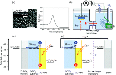 | ||
| Fig. 1 (a) SEM image and extinction spectrum of Au-NPs on SrTiO3. An inset figure shows the cross-sectional scanning transmission electron microscopy (STEM) image of Au-NPs on SrTiO3. (b) Schematic of the reaction cell. (c, d) Energy level diagrams of the SrTiO3 electrode loaded with Au-NPs on one side and Zr on the other side (c) and the two-electrode system using Au-NPs/SrTiO3 and Zr. The redox potentials U(N2/NH3) and U(O2/H2O) were obtained from the literature.28,29 | ||
Photoelectrochemical measurements on plasmon-induced NH3 synthesis
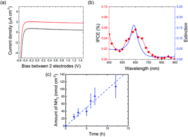
Fig. 2a depicts the current density and voltage (J–V) characteristics of the two-electrode system using a SrTiO3 photoanode loaded with Au-NPs and a Zr coil cathode (Au-NPs/SrTiO3|Zr coil). A good rectification property derived from the SrTiO3 was observed in dark conditions. Additionally, a stable photocurrent was observed under visible light irradiation over a wide range of applied biases. The photocurrent is derived from hot-electron-induced charge separation due to LSPR excitation because the action spectrum of the incident photon-to-current efficiency (IPCE) corresponds to the plasmon resonance spectrum, as shown in Fig. 2b, and the SrTiO3 does not absorb visible light longer than 390 nm.Fig. 2c shows the amount of NH3 evolved in the cathodic chamber as a function of irradiation time with visible light (410–800 nm) with an applied bias of 1.0 V. The amount of NH3 formed under visible light irradiation on the SrTiO3 loaded with Au-NPs linearly increased with increasing irradiation time, and the rate of NH3 formation was 10 nmol h−1 cm2. This rate is approximately 10 times larger than the reported with plasmonic ammonia synthesis systems.25 The larger reaction rate of NH3 photosynthesis was achieved due to the efficient ion transport path, the greater cathode surface area, and the continuous supply of N2 gas.
Bias and pH dependence of plasmon-induced NH3 synthesis
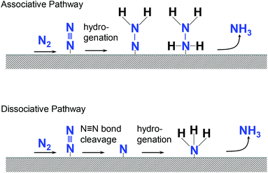
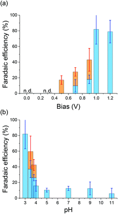
In principle, two types of reaction mechanisms are possible in the reduction of N2 to NH3, as shown in Fig. 3.29 One is an associative pathway in which N2 molecules on the catalyst are hydrogenated.30 The other is a dissociative pathway in which nitrogen and hydrogen react after the cleavage of the strong N2 triple bond.31 Enzymes such as nitrogenase follow the associative pathway as the activation energy is lower. However, the Haber–Bosch method uses the dissociative pathway. Understanding the reaction mechanism of NH3 formation on Zr will facilitate the development of selective and efficient NH3 synthesis techniques. Therefore, the effects of the applied potential and concentration of reactants on the reaction are important. Fig. 4a shows the faradaic efficiency (FE) of NH3 formation calculated from the amount of NH3 formed and the photocurrent as a function of the applied bias. Hydrazine (N2H4) was also measured by the colorimetric method because N2H4 is a possible intermediate in NH3 production through the associative pathway.12,32When the applied bias is small, no NH3 was detected. A small amount of NH3 was observed with an applied bias of 0.7 V. The FE of NH3 increased as the applied bias increased, reaching approximately 80% when the applied bias was 1.0 V. Additionally, N2H4 was observed when the applied bias was from 0.5 to 0.9 V. To understand the applied potential on the cathode in well-defined condition, the three-electrode electrochemical reaction was performed using Zr as the working electrode. The current–voltage characteristics of Zr under N2 (IN2) and Ar (IAr) bubbling conditions and the current enhancement by N2 calculated as (IN2 − IAr)/IN2 under dark conditions are shown in Fig. S2.†IN2 is larger than IAr over a wide range of applied potentials, and the current enhancement showed a maximum at −0.3 V vs. Ag/AgCl of the applied bias.
Fig. 4b depicts the FEs of NH3 and N2H4 as a function of pH under an applied bias of 1.0 V. It was confirmed that the pH was not increased during the reaction (Fig. S3†). The FE of NH3 was very poor when the pH was larger than 4.0. However, the FE of NH3 increased dramatically as the pH decreased below 4.0. In contrast, N2H4 was observed when the pH was between 3.5 and 4.0. This result indicates that the proton concentration directly affects NH3 production.
Notably, both the bias and pH dependencies indicate that intermediate values of bias and pH produce N2H4. These results suggest that reaction acceleration is needed for NH3 production, and N2H4 may be an intermediate in NH3 production. However, the reduction potential from N2 to N2H4 (−0.33 V vs. the reversible hydrogen electrode (RHE)) is negative relative to that from N2 to NH3 (0.09 V vs. RHE).32 Therefore, plasmon-induced NH3 formation via a six-electron and six-proton transfer process on Zr proceeded kinetically rather than thermodynamically. Also, there is a possibility that the produced N2H4 was consumed as a redox reagent due to the high reduction ability.33 Additionally, the sum of the FEs of NH3 and N2H4 does not equal 100% in the intermediate region. One of the other electron-consuming processes is the self-reduction of the Zr surface, and the other process is H2 production via proton reduction. H2 production was evaluated by using a sealed reaction cell. As a result, approximately 50% of the photocurrent was used for proton reduction under the applied bias of 0.7 V (Fig. S1b†). Also, the FE of H2 was less than detection limit under the applied bias of 1.0 V.
Proposed reaction mechanism
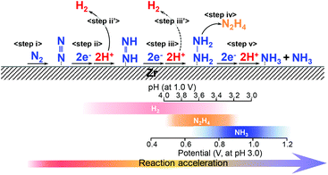
In previous reports using isotopic reactants, water oxidation on the plasmonic photoanode and NH3 evolution by N2 reduction on the Zr cathode proceeded via plasmon-induced NH3 synthesis.19,25 In particular, it was predicted that N2 is reduced by proton addition in the aqueous solution rather than the addition of a hydrogen adatom.Based on the results described above, we propose the plasmon-induced NH3 synthesis on Zr proceeds via an associative pathway in which N2 is hydrogenated by protons (Fig. 5). Initially, the N2 molecule is preferentially adsorbed on the Zr surface (step i).34,35 Subsequently, the reduction of N2 proceeds via proton addition (step ii) because the hypothesis that protons attach to the adsorbed N2 is supported by the dependence of the NH3 production on the proton concentration, as shown in Fig. 3b. When the pH was large and applied potential was low, H2 was also produced as a by-product (step ii′, iii′). Additionally, when the applied potential and proton concentration are moderate (pH 3.5–4.0 at applied bias of 1.0 V, or applied bias 0.5–0.9 V at pH 3.0), N2H4 is produced as the major product via a four-electron transfer process (step iii–iv). If the reaction rate is high enough with a large applied bias and a high proton concentration, NH3 is produced as the main product via a six-electron transfer process (step v). We conclude that the reason for the high selectivity in N2 conversion on Zr is due to the association process without direct cleavage of the strong N2 triple bond.
Experimental
Preparation of plasmonic photoanode
Au-NPs/SrTiO3 photoanode was fabricated according to the previous reports.19 The Au-NPs/SrTiO3 photoelectrode was fabricated by Helicon sputtering (ULVAC, MPS-4000C1/HC1) of 3 nm Au film on a single crystal of 0.05 wt% Nb-doped SrTiO3 (10 × 10 × 0.5 mm3, Furuuchi Chemical) with a (110) surface, and subsequent annealing at 800 °C in N2. The morphology of Au-NPs on the SrTiO3 was observed using field-emission scanning electron microscopy (FE-SEM, JSM-6700FT, JEOL); the maximum resolution attainable at an electron acceleration voltage of 15 kV was 1 nm. The cross-sectional structure of the Au-NPs/SrTiO3 was observed by STEM (Hitachi HD-2000 operated at 200 kV). The cross-sectional STEM sample was prepared using the focused ion beam technique (JEOL JIB-4600F/HKD) with Ga ions.Photoelectrochemical reaction
The N2 fixation device comprised reaction cells with two reaction chambers separated by the Nafion® 117 proton exchange membrane (Aldrich). An InGa alloy (2![[thin space (1/6-em)]](https://www.rsc.org/images/entities/char_2009.gif) :
:![[thin space (1/6-em)]](https://www.rsc.org/images/entities/char_2009.gif) 1 weight ratio) film was pasted onto the backside of the plasmonic photoanode and then connected to an electrochemical analyzer (ALS/CH Instruments 760DH (ALS)) as a photoanode with a copper lead wire. A Zr coil was used as a cathode. The surface area of the Zr coil was 0.628 cm2. An H2SO4 aqueous solution (pH 3) was filled in both chambers as the supporting electrolyte solution without any specific electron donor, and the N2 was bubbled in the cathodic chamber with 50 sccm during the reaction. When the pH of the solution was less than 4, the concentration of the electrolyte was kept as 0.05 mol dm−3 by the addition of Na2SO4. The photoanode was irradiated in an area of ∅ 6 mm (0.283 cm2) by a xenon lamp (800 W, Newport) using an arbitrary light intensity and wavelength, and the amount of NH3 formed per area was calculated by dividing the value by the irradiation area. For the IPCE calculation, the photocurrent was measured at 0 V between two-electrode. The IPCE was calculated by the following equation:
1 weight ratio) film was pasted onto the backside of the plasmonic photoanode and then connected to an electrochemical analyzer (ALS/CH Instruments 760DH (ALS)) as a photoanode with a copper lead wire. A Zr coil was used as a cathode. The surface area of the Zr coil was 0.628 cm2. An H2SO4 aqueous solution (pH 3) was filled in both chambers as the supporting electrolyte solution without any specific electron donor, and the N2 was bubbled in the cathodic chamber with 50 sccm during the reaction. When the pH of the solution was less than 4, the concentration of the electrolyte was kept as 0.05 mol dm−3 by the addition of Na2SO4. The photoanode was irradiated in an area of ∅ 6 mm (0.283 cm2) by a xenon lamp (800 W, Newport) using an arbitrary light intensity and wavelength, and the amount of NH3 formed per area was calculated by dividing the value by the irradiation area. For the IPCE calculation, the photocurrent was measured at 0 V between two-electrode. The IPCE was calculated by the following equation:where J is the photocurrent density generated by monochromatic light with a bandwidth of less than 15 nm, λ is the wavelength of the monochromatic incident light, and P is the light intensity. Bandpass filters with a bandwidth of less than 15 nm at the full-width at half-maximum were used.
The FEs of NH3 and N2H4 were calculated by the following equation:
![[thin space (1/6-em)]](https://www.rsc.org/images/entities/char_2009.gif) 485 C mol−1, n is the number of electrons involved in the reaction, Q is the total charge passed through the whole reaction.
485 C mol−1, n is the number of electrons involved in the reaction, Q is the total charge passed through the whole reaction.
Assays
The quantity of NH3 formed and evolved H2 were determined using the procedure using sodium salicylate, pyrazole, sodium hypochlorite, and sodium hydroxide.25 We passed 0.5 mL of deionized water through the cathodic chamber to fully dissolve the NH3 (gas phase) and NH4Cl (aqueous solution) formed. After the solution was neutralized to pH 7 using a 1.5 mol dm−3 sodium hydroxide aqueous solution, the following materials were added successively; 0.08 mL of an aqueous solution of ethylenediaminetetraacetic acid tetrasodium salt hydrate (1.3 mol dm−3); 0.16 mL of an aqueous solution of sodium salicylate (1.46 mol dm−3) and pyrazole (0.24 mol dm−3); 0.52 mL of an aqueous solution of sodium hydroxide (1.25 mol dm−3) and sodium hypochlorite (0.25 mol dm−3). The sodium salicylate formed a dimer in the presence of NH3 with absorption at λmax = 650 nm. Ammonium chloride was purchased (Wako chemical, LTD) and used for calibration. The absorption spectra were monitored using a UV/vis spectrometer (UV-3100, Shimadzu). The value for NH3 formation at 0 hours was subtracted from all of the data as the background.The quantity of formed N2H4 was determined by a colorimetric method using organic probe 3-cyano-7-hydroxycoumarin levulinate (CHCL). CHCL was synthesized according to the literature as shown in Scheme S1.†![[thin space (1/6-em)]](https://www.rsc.org/images/entities/char_2009.gif) 36 Oxalyl chloride (0.82 mL, 8.6 mmol) and DMF (10 μL) were added to a suspension of levulinic acid (502 mg, 4.3 mmol) in dichloromethane (50 mL). The reaction mixture was stirred at room temperature for 4 h, and the volatiles were evaporated under reduced pressure and subsequently dried with vacuum pumping. The residue was dissolved in a small amount of dry dichloromethane. The solution was slowly added to the dispersed dichloromethane solution (50 mL) containing 3-cyano-7-hydroxycoumarin (CHC, 284.6 mg, 1.5 mmol) and triethylamine (0.55 mL, 3.9 mmol) at 0 °C. After stirring for 12 h at r.t., the reaction mixture was filtered, and the solution phase was treated with water. The organic phase was separated and washed with 1 mol dm−3 sodium bicarbonate solution and water and then evaporated to obtain a solid residue. The product was purified by crystallization from dichloromethane and toluene to obtain CHCL. Yield, 18%.
36 Oxalyl chloride (0.82 mL, 8.6 mmol) and DMF (10 μL) were added to a suspension of levulinic acid (502 mg, 4.3 mmol) in dichloromethane (50 mL). The reaction mixture was stirred at room temperature for 4 h, and the volatiles were evaporated under reduced pressure and subsequently dried with vacuum pumping. The residue was dissolved in a small amount of dry dichloromethane. The solution was slowly added to the dispersed dichloromethane solution (50 mL) containing 3-cyano-7-hydroxycoumarin (CHC, 284.6 mg, 1.5 mmol) and triethylamine (0.55 mL, 3.9 mmol) at 0 °C. After stirring for 12 h at r.t., the reaction mixture was filtered, and the solution phase was treated with water. The organic phase was separated and washed with 1 mol dm−3 sodium bicarbonate solution and water and then evaporated to obtain a solid residue. The product was purified by crystallization from dichloromethane and toluene to obtain CHCL. Yield, 18%.
The chromogenic signalling behaviour of CHCL was investigated in a 30% aqueous acetonitrile solution at pH 6.8 (phosphate buffer, 10 mM). CHCL revealed moderate UV-vis absorption at 336 nm. Upon the interaction of CHCL with hydrazine, a prominent absorption band centered at 416 nm developed which is a characteristic of CHC. The changes in absorption bands by the hydrazine-induced deprotection process were used as a ratiometric analysis for the transformation of probe CHCL to CHC.
The calibration curves for NH3 and N2H4 were shown in Fig. S4.†
Conclusions
In summary, a two-electrode plasmon-induced NH3 synthesis system that enables electrical and chemical analysis was fabricated. The bias and pH dependences of the reaction were systematically investigated, and the mechanism of the plasmon-induced NH3 synthesis on Zr was proposed follow an associative pathway. The results presented herein provide crucial insight into the design of catalysts and electrodes for plasmon-induced NH3 synthesis. As an aspect of the plasmonic photoanode, higher absorptivity and charge separation efficiency are required to produce a larger number of hot-electrons.Future studies are aimed at increasing the reaction yield while maintaining high selectivity. The innovative development of the plasmonic photoanode, such as the coupling between plasmons and the other photonic mode, offers enhanced charge separation efficiency.37,38 Time-resolved measurements of the near and far fields are also important for understanding the plasmon decay and the generation and transportation of the photocarriers.39–41 Additionally, the development of oxidation co-catalysts is indispensable for quickly consuming the photogenerated holes.42–44 The development of high-performance cathodes and co-catalysts for nitrogen reduction is also indispensable. Although further improvement of the reaction activity is needed, this robust plasmonic NH3 synthesis system under visible light irradiation could facilitate the utilization of NH3 as an energy carrier.
Conflicts of interest
The authors declare no conflict of interest.Acknowledgements
We acknowledge financial support from JSPS KAKENHI (Grant No. JP18H05205, JP17H01041, JP19H02737, JP19H04667, and JP18K05053), the Nanotechnology Platform (Hokkaido University), and the Dynamic Alliance for Open Innovation Bridging Human, Environment and Materials (Five-Star Alliance) of MEXT.Notes and references
- L. Green, Int. J. Hydrogen Energy, 1982, 7, 355–359 CrossRef CAS.
- R. Lan, J. T. S. Irvine and S. Tao, Int. J. Hydrogen Energy, 2012, 37, 1482–1494 CrossRef CAS.
- A. Q. Fenwick, J. M. Gregoire and O. R. Luca, J. Photochem. Photobiol., B, 2015, 152, 47–57 CrossRef CAS PubMed.
- K. Aika, L. J. Chiristiansen, I. Dybkjacr, J. B. Hansen, H. Nielsen, A. Nielsen, P. Stoltze and K. Tamaru, Ammonia, Springer, Germany, 1995 Search PubMed.
- R. Schlogl, Angew. Chem., Int. Ed., 2003, 42, 2004–2008 CrossRef PubMed.
- G. Ertl, Angew. Chem., Int. Ed., 2008, 47, 3524–3535 CrossRef CAS PubMed.
- M. Kitano, Y. Inoue, Y. Yamazaki, F. Hayashi, S. Kanbara, S. Matsuishi, T. Yokoyama, S. W. Kim, M. Hara and H. Hosono, Nat. Chem., 2012, 4, 934–940 CrossRef CAS PubMed.
- M. Kitano, S. Kanbara, Y. Inoue, N. Kuganathan, P. V. Sushko, T. Yokoyama, M. Hara and H. Hosono, Nat. Commun., 2015, 6, 6731 CrossRef CAS PubMed.
- J. Rittle and J. C. Peters, J. Am. Chem. Soc., 2016, 138, 4243–4248 CrossRef CAS PubMed.
- A. R. Singh, B. A. Rohr, J. A. Schwalbe, M. Cargnello, K. Chan, T. F. Jaramillo, I. Chorkendorff and J. K. Nørskov, ACS Catal., 2017, 7, 706–709 CrossRef CAS.
- D. Bao, Q. Zhang, F. L. Meng, H. X. Zhong, M. M. Shi, Y. Zhang, J. M. Yan, Q. Jiang and X. B. Zhang, Adv. Mater., 2017, 29, 1604799 CrossRef PubMed.
- Y. Yao, S. Zhu, H. Wang, H. Li and M. Shao, J. Am. Chem. Soc., 2018, 140, 1496–1501 CrossRef CAS PubMed.
- G. N. Schrauzer and T. D. Guth, J. Am. Chem. Soc., 1977, 99, 7189–7193 CrossRef CAS.
- O. Rusina, A. Eremenko, G. Frank, H. P. Strunk and H. Kisch, Angew. Chem., Int. Ed., 2001, 40, 3993–3995 CrossRef CAS PubMed.
- H. Li, J. Shang, Z. Ai and L. Zhang, J. Am. Chem. Soc., 2015, 137, 6393–6399 CrossRef CAS PubMed.
- Y. Lu, Y. Yang, T. Zhang, Z. Ge, H. Chang, P. Xiao, Y. Xie, L. Hua, Q. Li, H. Li, B. Ma, N. Guan, Y. Ma and Y. Chen, ACS Nano, 2016, 10, 10507–10515 CrossRef CAS PubMed.
- H. Hirakawa, M. Hashimoto, Y. Shiraishi and T. Hirai, J. Am. Chem. Soc., 2017, 139, 10929–10936 CrossRef CAS PubMed.
- S. Linic, P. Christopher and D. B. Ingram, Nat. Mater., 2011, 10, 911–921 CrossRef CAS PubMed.
- Y. Zhong, K. Ueno, Y. Mori, X. Shi, T. Oshikiri, K. Murakoshi, H. Inoue and H. Misawa, Angew. Chem., Int. Ed., 2014, 53, 10350–10354 CrossRef CAS PubMed.
- M. Ali, F. Zhou, K. Chen, C. Kotzur, C. Xiao, L. Bourgeois, X. Zhang and D. R. MacFarlane, Nat. Commun., 2016, 7, 11335 CrossRef CAS PubMed.
- K. Ueno, T. Oshikiri and H. Misawa, ChemPhysChem, 2016, 17, 199–215 CrossRef CAS PubMed.
- C. Li, T. Wang, Z. J. Zhao, W. Yang, J. F. Li, A. Li, Z. Yang, G. A. Ozin and J. Gong, Angew. Chem., Int. Ed., 2018, 57, 5278–5282 CrossRef CAS PubMed.
- J. S. DuChene, G. Tagliabue, A. J. Welch, W. H. Cheng and H. A. Atwater, Nano Lett., 2018, 18, 2545–2550 CrossRef CAS PubMed.
- T. Oshikiri, K. Ueno and H. Misawa, Angew. Chem., Int. Ed., 2014, 53, 9802–9805 CrossRef CAS PubMed.
- T. Oshikiri, K. Ueno and H. Misawa, Angew. Chem., Int. Ed., 2016, 55, 3942–3946 CrossRef CAS PubMed.
- Y. Nishijima, K. Ueno, Y. Kotake, K. Murakoshi, H. Inoue and H. Misawa, J. Phys. Chem. Lett., 2012, 3, 1248–1252 CrossRef CAS PubMed.
- X. Shi, K. Ueno, N. Takabayashi and H. Misawa, J. Phys. Chem. C, 2013, 117, 2494–2499 CrossRef CAS.
- J. L. Ord, J. Electrochem. Soc., 1995, 142, 879–882 CrossRef CAS.
- M. A. Shipman and M. D. Symes, Catal. Today, 2017, 286, 57–68 CrossRef CAS.
- B. M. Hoffman, D. R. Dean and L. C. Seefeldt, Acc. Chem. Res., 2009, 42, 609–619 CrossRef CAS PubMed.
- T. H. Rod, A. Logadottir and J. K. Nørskov, J. Chem. Phys., 2000, 112, 5343–5347 CrossRef CAS.
- B. M. Lindley, A. M. Appel, K. Krogh-Jespersen, J. M. Mayer and A. J. M. Miller, ACS Energy Lett., 2016, 1, 698–704 CrossRef CAS.
- L. J. Kamphake, S. A. Hannah and J. M. Cohen, Water Res., 1967, 1, 205–216 CrossRef CAS.
- C. Reimann and T. Bredow, J. Mol. Struct.: THEOCHEM, 2009, 903, 89–99 CrossRef CAS.
- E. Skulason, T. Bligaard, S. Gudmundsdottir, F. Studt, J. Rossmeisl, F. Abild-Pedersen, T. Vegge, H. Jonsson and J. K. Norskov, Phys. Chem. Chem. Phys., 2012, 14, 1235–1245 RSC.
- M. G. Choi, J. Hwang, J. O. Moon, J. Sung and S. K. Chang, Org. Lett., 2011, 13, 5260–5263 CrossRef CAS PubMed.
- X. Shi, K. Ueno, T. Oshikiri, Q. Sun, K. Sasaki and H. Misawa, Nat. Nanotechnol., 2018, 13, 953–958 CrossRef CAS PubMed.
- J. Yang, Q. Sun, K. Ueno, X. Shi, T. Oshikiri, H. Misawa and Q. Gong, Nat. Commun., 2018, 9, 4858 CrossRef PubMed.
- A. Furube, L. Du, K. Hara, R. Katoh and M. Tachiya, J. Am. Chem. Soc., 2007, 129, 14852–14853 CrossRef CAS PubMed.
- Q. Sun, K. Ueno, H. Yu, A. Kubo, Y. Matsuo and H. Misawa, Light: Sci. Appl., 2013, 2, e118 CrossRef CAS.
- Q. Sun, H. Yu, K. Ueno, A. Kubo, Y. Matsuo and H. Misawa, ACS Nano, 2016, 10, 3835–3842 CrossRef CAS PubMed.
- R. D. Smith, M. S. Prevot, R. D. Fagan, S. Trudel and C. P. Berlinguette, J. Am. Chem. Soc., 2013, 135, 11580–11586 CrossRef CAS PubMed.
- A. Iwase, S. Yoshino, T. Takayama, Y. H. Ng, R. Amal and A. Kudo, J. Am. Chem. Soc., 2016, 138, 10260–10264 CrossRef CAS PubMed.
- K. Maeda, K. Ishimaki, Y. Tokunaga, D. Lu and M. Eguchi, Angew. Chem., Int. Ed., 2016, 55, 8309–8313 CrossRef CAS PubMed.
Footnotes |
| † Electronic supplementary information (ESI) available. See DOI: 10.1039/c9gc01658a |
| ‡ The present address of Prof. K. Ueno is Department of Chemistry, Faculty of Science, Hokkaido University, Sapporo 060-0810 (Japan). |
| This journal is © The Royal Society of Chemistry 2019 |

