
 Open Access Article
 This Open Access Article is licensed under a
 Creative Commons Attribution 3.0 Unported Licence
Continuous manufacturing – the Green Chemistry promise?
Luke
Rogers†
and
Klavs F.
Jensen

Department of Chemical Engineering, MIT, 77 Massachusetts Avenue, Cambridge, MA 02139, USA. E-mail: kfjensen@mit.edu
First published on 21st May 2019
Abstract
Continuous manufacturing and Green Chemistry, are two promising approaches to synthesis with underutilized potential that are gaining traction by the wider pharmaceutical community. We review Green Chemistry advances resulting when transitioning to continuous manufacturing with focus on Green Chemistry elements inherent in flow chemistry and related separation processes. Case studies of continuous manufacturing represented by the F3 (Flexible, Fast, and Future) project, cGPM manufacturing at Eli Lilly, and the MIT pharmaceuticals on demand projects provide examples of Green Chemistry advances realised. Throughout the review, Green Chemistry advances are identified in terms of the pertinent principles of Green Chemistry. A count of the occurrences of the different principles of Green Chemistry reveals that the principle of prevention greatly overshadows all other principles.
Introduction
There are a number of excellent reviews on Green Chemistry and its benefits,1–11 but few of these reviews focus on continuous manufacturing and its potential for advancing applications of Green Chemistry principles.12–14 For new adopters of the technology, we begin by providing a high-level introduction to continuous manufacturing and its intrinsic link to Green Chemistry principles. We focus on how manufacturing, regulatory and research organizations, and the implementation of continuous manufacturing will aid efforts to advance the 12 principles of Green Chemistry. We also discuss advantages of transitioning to continuous manufacturing and for which processes it has the potential to be most impactful, along with some of the current challenges and pitfalls associated with continuous manufacturing. We seek to address key unit operations that could aid the transition to continuous manufacturing while also highlighting underused unit operations in the continuous manufacturing framework that have significant upside potential. Throughout the review, we will reference the pertinent core Green Chemistry principles by the reference codes listed in Table 1.| Code | Green Chemistry principle |
|---|---|
| G1 | Prevention |
| G2 | Atom economy |
| G3 | Less hazardous chemical syntheses |
| G4 | Designing safer chemicals |
| G5 | Safer solvents and auxiliaries |
| G6 | Design for energy efficiency |
| G7 | Use of renewable feedstocks |
| G8 | Reduce derivative |
| G9 | Catalysis |
| G10 | Design for degradation |
| G11 | Real-time analysis for Pollution Prevention |
| G12 | Inherently safer chemistry for accident prevention |
Those already involved in continuous manufacturing will be aware of the overlap of Green Chemistry approaches with benefits gained by converting to continuous manufacturing. For researchers newer to the field, Table 2 serves as an introduction to the environmental and economic advantages accrued by implementing continuous manufacturing.
| Thinking environmental | Thinking economic | Thinking continuous | |
|---|---|---|---|
| Atom economy | Minimal byproduct formation. Reduced environmental burden (G2) | More from less, incorporate total value of materials. Reduced cost | Larger toolbox of reactions due to increased safety and process intensification |
| Solvent reduction | Less solvent required, less solvent waste. Reduced environmental burden (G1) | Reduced capacity requirements, less energy required. Reduced cost | Reduced solvent volumes through the elimination of large reactors |
| Reagent optimization | Catalytic, low stoichiometry, recyclable Reduced environmental burden (G9) | Higher efficiency, higher selectivity. Reduced cost | Increased process understanding and thus, increased process performance |
| Convergency | Reduced environmental burden (G2,9) related to improved process efficiency | Higher efficiency, fewer operations. Reduced cost | Fewer potential intermediate and/or product isolations |
| Energy reduction | Reduced environmental burden (G6) related to power generation, transport, and use. | Increased efficiency, shorter processes, milder conditions. Reduced cost | Smaller energy requirements to run continuous platforms |
| In situ analysis | Reduced potential for exposure or release to the environment (G11) | Real time data increases throughput and efficiency, fewer reworks. Reduced cost | Large utilization of PAT for CM to ensure product quality and reduce burden for final product testing |
| Safety | Nonhazardous materials and processes reduce risk of exposure, release, explosions, and fires (G12) | Worker safety and reduced down time. Reduced special control measures. Reduced cost | Small volumes of hazardous materials being processed at any given time, increased control over process parameters |
Green metrics
Metrics are needed to quantify the impact of these new methodologies, be it within a pharmaceutical company, Contract Manufacturing Organization (CMO). Which metric is best is more a question of organization/personal preference. Process Mass Intensity (PMI) and E-Factor are currently the two most favourable.15 The Green Chemistry Institute Pharmaceutical Roundtable (GCIPR) selected PMI as their preferred mass-based Green metric. Jimenez-Gonzalez et al. discuss the other available metrics and the ultimate decision to select PMI.16 Their rationale was that PMI is defined as the total mass of material used to produce a specified mass of a particular product (eqn (1)) This focus on process efficiency provides the opportunity for an holistic implementation of Green Chemistry ideologies, and not just that of waste.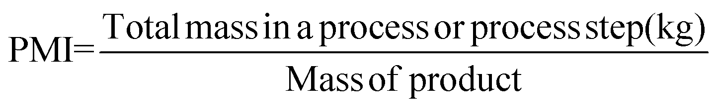 | (1) |
This metric incorporates reactants, solvents, reagents etc. used during the process whereas E-factor solely focuses on waste.17,18 A PMI of 1 is a scenario where no process waste is produced and all materials are assimilated into the product. PMI takes a holistic approach to Green efficiency, incorporating the entire manufacturing process. This results in the inclusion of any outsourcing to CMO's, compelling companies to implement Green and efficient practices across their supply chain. Furthermore, companies have realised that the nature of the waste (e.g., the toxicity) along with the absolute quantity of waste is of increasing importance towards becoming Greener. As such they have started incorporating key waste contributors into their life cycle assessment tools to help prioritize areas for improvement.19
Solvent
When evaluating a process, solvents are usually the determining factor in the environmental impact, cost and safety.20 Process solvents can constitute up to 80–90% of the non-aqueous mass of materials to manufacture API (Fig. 1) (G1, G5).21 Other reports have estimated that solvents can account for 50% of Greenhouse gas emissions from the production of pharmaceuticals.22 This figure might not be overly surprising when surveys report that 56% of materials used for API manufacturing are organic solvents.16 These statistics may indicate why the 15 members of the GCIPR have highlighted greener solvent usage as a strategic priority, so much so that its 2010 call for proposals centred on solvent-less reactor cleaning, suitable replacements for dipolar aprotic solvents, and other solvent-related research. Chlorinated hydrocarbons, so long the workhorse of chemical reactions, have become very taboo, to such an extent that as an example, Pfizer has not scaled a process that uses one in the last eight years (G3, G4, G5, G7).18 It is perhaps one of the most telling indicators that processes must be examined holistically to ensure maximum efficiency. A report from GSK stated that less than 50% of solvent used is recycled and reused (G1).21 Cross-contamination from the use of different solvents in a multi-step synthesis can make solvent recovery expensive and energy-intensive. Amgen, in partnership with Bachem, were successful in improving their manufacturing process of the active ingredient of Parsabiv™, their drug used in the treatment of secondary hyperparathyroidism in adult patients with chronic kidney disease. Their improved solid-phase peptide manufacturing process resulted in a 71% reduction in solvent use and a 56% reduction in manufacturing operating time.23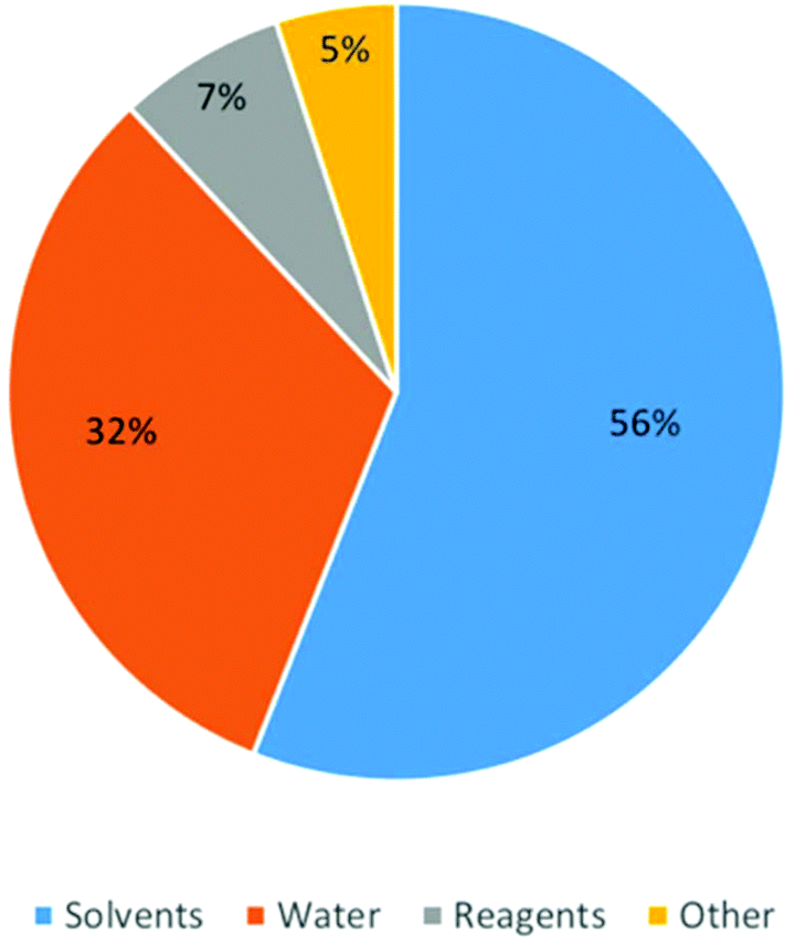 | ||
| Fig. 1 Pie chart characterizing the composition by mass of the different types of material used in the Pharmaceutical industry. Reprinted with permission from Wiley and Sons.16 | ||
When trying to implement greener solvents into a process, cost and availability become important considerations.18,24 The potential use of supercritical fluids, ionic liquids (IL), and other solvents is covered in reviews by Pollet et al. and Bubalo et al.8,25,26 None of these options have so far achieved widespread commercial application despite their high profile in the publication landscape. When designing a process, solvent choice needs to be included along with process performance. Otherwise, an after-thought approach to solvent and purely yield-driven focus risks leading to overuse of ‘unfavorable’ solvents.
Continuous manufacturing in industry
The pharmaceutical industry faces strict regulatory hurdles, so innovation can be slowed by uncertainty about the impact of a new manufacturing approach on the potential success of future filings. Nevertheless, driven by quality by design (QbD) approaches and opportunities for greater process intensification, i.e., higher production with less use of space, energy, and raw materials, the industry has explored continuous manufacturing from individual unit operations to end-to-end manufacturing.27 As necessary as the paradigm shift towards ‘Green Chemistry’ has been in moving towards more sustainable business practices for the pharmaceutical industry, it is equally crucial that chemical process technology evolves in parallel.16 The marriage of continuous manufacturing and Green Chemistry could present an attractive avenue as the industry moves towards sustainable production of increasing broader and competitive production portfolios.28The environmental impact of manufacturing pharmaceuticals has typically been higher than most chemical industries (G1, G3, G5, G6, G11).28 Continuous unit operations are not new concepts to the pharmaceutical industry as technologies such as dry blending, spray drying, granulation, and extrusion have seen utilized for years.29 However, these continuous operations, until recently, were still being implemented as isolated “bin to bin” processing steps. A holistic approach to continuous manufacturing requires the logistical hurdles of integrating a train of unit operations, typically in a pre-existing facility, along with the establishment of control systems and process monitoring strategies.
While end-to-end manufacturing of drug substance remains elusive, successful commercial filings by Vertex for their Orkambi tablets and Janssen for Prezista tablets has demonstrated the effective utilization of continuous manufacturing in the drug product domain.30–33 Capital investment by Eli Lilly for their new continuous manufacturing site in Kinsale, Ireland and GlaxoSmithKline's creation of a commercial-scale continuous system (Fig. 2) in Singapore, a site that promises 50% reduction in carbon footprint and 50% reduction in costs, demonstrates the pharmaceutical industry's willingness to adapt to continuous manufacturing (G6, G11). GSK believes that anywhere between one-third and one-half of their drug portfolio could be transitioned to continuous manufacturing.34 In addition to building the Singapore plant for GSK, Zeton, a global equipment and process technology supplier, recently helped design, build and install a continuous API manufacturing skid for GSK in their Global R&D hub in Upper Providence, Pa.35 These implementations represents important advances, but continuous manufacturing and Green Chemistry's true potential will only be achieved if researchers are rewarded for innovation through the introduction of Green and continuous processes from a top-down “business excellence” decision as it requires a joint team and organizational effort.14
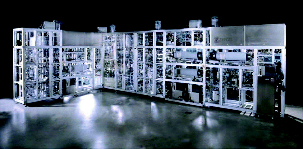 | ||
| Fig. 2 Continuous API Manufacturing Pilot Plant supplied by Zeton to GSK.36 | ||
A balance between in-house manufacturing and the utilization of CMOs has always existed in the pharmaceutical industry. If a significant transition to Green and continuous manufacturing for pharmaceutical companies’ pipelines transpires, then CMOs must also adapt continuous manufacturing and Green approaches. Catalent, Aesica, Snapdargon Chemistry, and Patheon (now Thermo Fischer) are CMOs and CROs that have invested early in continuous manufacturing technologies, Patheon recently investing in a 50 kg h−1 powder-to-tablet continuous manufacturing system.37,38 This potential for improved efficiency across all process facets will demonstrate the true intent of the pharmaceutical industry to Green and continuous manufacturing methodologies.
To help scientists progress, ASTM International has introduced a “Standard Guide or Application on Continuous Processing in the Pharmaceutical Industry” (ASTM E2968).39 It is intended to familiarize process intensification and production scientists with concepts and principles associated with continuous processing technologies for the pharmaceutical industry. From common terminology and process design principles to process control strategies and product quality control, this guide aims to reduce the learning curve required by both drug substance and/or drug product teams looking to establish a continuous manufacturing system within their respective organizational framework.
Regulatory landscape/current approval and drugs
The Pharmaceutical Industry's adoption of continuous manufacturing and the intrinsic Green benefits associated with it will live or die with the regulatory agencies’ approval processes. Emerging technologies have been a strategic initiative for innovation by the FDA.40 Emerging technologies encompasses any technology that has the potential to alleviate failures in quality, encourage more robust processing with fewer product failures, and help ensure that the product will provide expected clinical performance. Early and open dialogue between organizations and regulatory bodies is paramount. The FDA's Emerging Technology Program (ETP) has conducted ∼60 industrial interactions to date, one-third of those requests pertaining to continuous manufacturing. Many companies, while embracing continuous manufacturing and developing flow steps, continue to develop batch processes as a backup plan in case of challenges in the submission process. One of the most common regulatory questions asked of continuous manufacturing centres on the definition of a batch or lot. This is pertinent in the cases of accepting/rejecting material and for the cases involving product recalls. Recent draft guidelines for “Quality Considerations for Continuous Manufacturing” provided by the FDA quote the definition of a batch/lot utilized in 21 Code of Federal Regulations (CFR) 210.3. Once established before each production run, a batch can be a quantity of material processed, produced, a production period etc.41As such, in principle, there are no regulatory hurdles for implementing continuous manufacturing, but it is an evolving process with both the FDA and industry continually gaining experience. The Quality by Design (QbD) initiative championed by the FDA, which states that “quality cannot be tested into a product; it must be built in or present by design”, aligns strongly with continuous manufacturing. Akin to the QbD paradigm, continuous manufacturing mandates a higher level of process design to ensure adequate process control and product quality.42–47 The use of Design of Experiments (DoE) to gain large amounts of experimental information using reduced volumes of raw material (G1, G2) offers practical process understanding and process intensification phases during development and commercialization.48 A robust control strategy, process monitoring, and Real Time Release Testing (RTRT) are critical elements of the lifecycle for a continuous manufacturing process (Fig. 3). The use of process models and RTD studies will aid in the traceability of material through the equipment train and help real-time decision making or retrospective analyses.49–51 The control strategy is a key feature of the regulatory submission for continuous manufacturing processes. Thus, it needs to be designed to control product quality and be resilient to variations in the process, incoming raw materials, equipment conditions, or environmental factors over time.52 Effective control relies heavily on the implementation of process analytical technology (PAT), from parametric measurements like temperature, pressure and flow rate to on-line concentration measurement by vibrational spectroscopy (e.g., Fourier-transform infrared spectroscopy (FTIR) or Raman) and HPLC.40
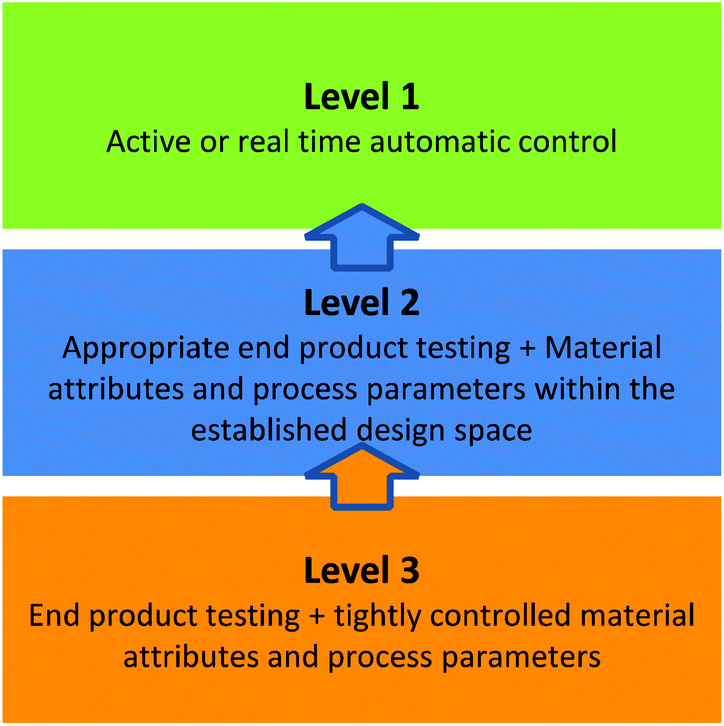 | ||
| Fig. 3 Categorization of potential controls and testing levels available for control strategies in pharmaceutical manufacturing.52 | ||
Process analytic techniques
PAT will be referenced throughout this review as it is integral to science and risk control framework underlying continuous manufacturing processes. Real-time release testing is an initiative that should become synonymous with continuous manufacturing as both concepts champion the use of online monitoring. For more information on the use of PAT for continuous manufacturing and its integration into a process control strategy, the 2004 guidance for industry is an excellent entry point.53PAT will heavily feature in many different components of a continuous manufacturing equipment train. Its most important role will probably be in the detection of deviations in real-time and facilitate the contemporaneous diversion of “out of spec” material. However, within the sphere of API synthesis, PAT provides an opportunity to improve the performance of a continuous process and aid in waste prevention through an increase in process understanding (G1) coupled with feedback control and on-line optimization.
Drug substance unit operations
Traditional pharmaceutical production uses batch chemistry. A processing mode where solvents, reactants, reagents etc., are placed in a reactor and allowed to mix at specific temperature and time point. This material is then carried forward to the next reactor and so forth. In many cases, researchers see batch chemistry as natural hold points in lengthy processes. These stoppages allow for the potential re-working of out of specification material as well as a stop gap if downstream equipment trains aren't ready to receive the incoming material (provided there are stability data that indicates that this is acceptable). Despite the maturation of the continuous manufacturing toolkit it is likely that there will always be scientific and economic drivers to incorporate batch steps in a process. Implement continuous processing when it makes scientific or business sense; not every unit operation will lend itself to efficient continuous manufacturing. Thus, it can be unproductive to forcefully transition a step or process to continuous manufacturing. The following section aims to discuss some of the main outstanding challenges that may be limiting the realisation of end-to-end continuous manufacturing.Flow chemistry
Flow chemistry provides researchers the opportunity for decreased solvent utilization through the increased implementation of solvent-free syntheses (the typical mass transfer issues related to these conditions can be more readily overcome in flow) and more atom-efficient reactions (G2).6,54–56 The telescoping of reaction pathways in flow has allowed for a decrease in waste generation by minimizing solvent switching steps and/or product isolations, which both increase process complexity (G1). Researchers have observed a 10x reduction in solvent consumption in their flow lab compared to their traditional synthesis facility.57 The process intensification afforded by flow chemistry can enable significant improvements in yield, product quality, and efficiency.58,59 It may also facilitate the expansion of the Green Chemistry “toolbox” of favourable chemical reactions.17The recent publication of a rapid 5 step telescoped synthesis of the API ciprofloxacin (Scheme 1) serves as an example.60 Acetonitrile is the reaction solvent for the first three reaction steps. Addition of the penultimate reagents in dimethyl sulfoxide (DMSO) provides sufficient solubility of the reaction product to nullify the need for in-line isolation and solvent switch unit operations, thus reducing process waste and eliminating downtime between synthetic steps.
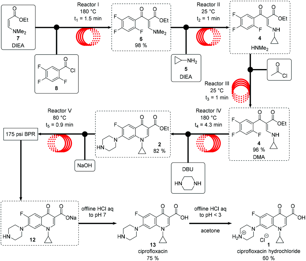 | ||
| Scheme 1 Telescoped scheme for the continuous flow production of Ciprofloxacin. Adopted and reprinted with permission from Wiley & Sons.60 | ||
Many recent reviews on flow chemistry as a means of being Green for academic and industrial settings are currently available, with Lummiss et al., Martin et al., Dallinger et al., to name a few of the recent examples.61–63 However, few reports treat continuous manufacturing as a holistic approach to improving Green manufacturing. The plethora of unit operations available to chemists and chemical engineers have been redesigned for continuous API manufacturing, typically as isolated steps. However, the linking of these into one continuous process is still a challenging exercise with considerations to be made with respect to both technical, business and environmental factors.
Reactor selection
Batch chemical synthesis, whether at lab or manufacturing scale, takes place in well-established reactors, e.g., round-bottom flasks or large batch vessels. However, with the emergence of flow chemistry, researchers can either acquire commercial flow setups made by an increasing number of companies (Syrris, Vapourtec, Ehrfeld and Corning) or use in-house prototypes.64–67 Due to the early stage of the field, and lack of industry standards, variance across platforms can result in performance discrepancies. The performance and chemical compatibility of pumps, valves, and back pressure regulators, along with heat and mass transfer rates, will cause difficulties when scaling-up or scaling-out processes.68 Pumping strategies remains a primary limiting factor to the expansion of flow chemistry. Syringe pumps,69 HPLC pumps, peristaltic pumps etc., all have their virtues, however, simultaneously achieving high-pressure capabilities, chemical compatibility, and a small footprint has been a challenge. Milligat pumps designed by Vici Valco have been rated to 250 psi and can withstand some aggressive chemicals whilst pumping at moderately high flow rates (up to 20 mL min−1).70Recent reviews by Jensen or Plutschack et al., provide in-depth analysis of basic principles and fundamentals such as flow capabilities, reactor selection, and commercial platforms readily available to researchers.71–73 A Nature Protocols paper by Britton et al., provides methodologies, equipment lists and detailed step-by-step instructions for the set-up of these commercial or personalized flow platforms (Fig. 4).74
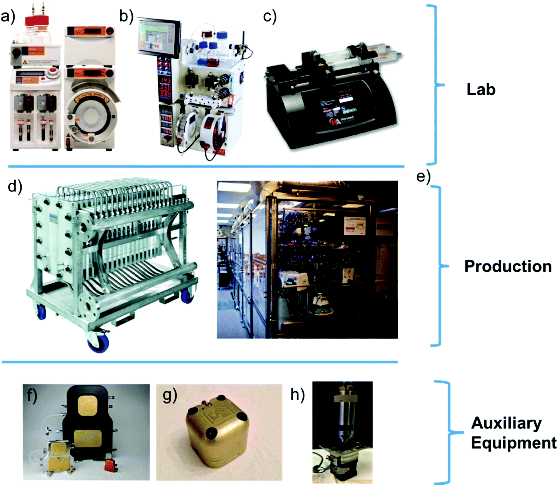 | ||
| Fig. 4 Examples of commercial flow setups currently available to researchers and some individual commercial components that can enable researchers create their own setup. (a) Syrris Asia platform,64 (b) Vapourtec R-series flow platform,65 (c) Harvard Syringe pump,69 (d) Corning G4 Flow System,67 (e) Novartis Continuous Manufacturing Skid at MIT,75 (f) Zaiput liquid–liquid separator range76 (g) Zaiput back-pressure regulator,77 and (h) Vici Valco Milligat M50 pump.70 | ||
The benefits of these platforms are constantly being demonstrated: short reaction times,54,78 reduced derivatization (G8), safe handling of hazardous reagents (G12)79,80 Greener processes13,81 and multi-step telescoped sequences (G1, G2).82,83 The development of a wide range of flow chemical pathways has enabled the successful synthesis of several APIs.84–87
Photochemistry has recently emerged as a Green option for the Pharmaceutical Industry (G4, G5, G7, G9).72 Photochemical experimental setups in flow offer more efficient irradiation of reaction mixtures and facilitate a more straightforward route to scaling photochemical reactions (i.e., due to the Beer–Lambert law).88 The dimensions of a typical flow reactor (diameter <10 mm) allows for sufficient exposure of the reaction stream to light, thus reactions are less likely to be limited by the photon flux. As with thermal reactors, options for photochemical reactors have bifurcated into home-built and commercial platforms, essentially light-transparent chips or coil reactors.89–91 Photochemistry's true niche is the formation of synthetically inaccessible molecules. Challenging through standard chemical transformations, the utilization of cycloadditions, cyclizations, rearrangements and radical chain processes enables these molecules to be synthesized.92 Some photochemical reactions can even proceed without additional reagents, making them outstanding examples of Green processing. A recent review by Cambie et al., covers the great strides made by flow photochemistry researchers and provides a comprehensive overview of the field and the current state of the art.93
Catalysis/bio-catalysis
The increasing need for Greener API manufacturing has elicited a shift in focus towards catalytic processes, be it homogeneous, heterogeneous, biological, or organocatalysis.94 There are substantial business drivers for their inclusion into processes due to the potential for an increased yield accompanied by a reduction in waste generation, time, and energy required (G6, G9). Reactions such as hydrogenations, oxidations, ring-closing metathesis, or cross-couplings have been utilized in the production of APIs. This shift away from stoichiometric, non-selective reagents is a primary goal for the pharmaceutical industry (G2, G8).95 In homogenous processes, complete removal and, if possible, recycling of the catalyst is essential to ensure product quality and lower costs.96 Heterogeneous catalysis can offer certain advantages; however, catalyst immobilization without significant leaching has proven challenging.97,98Biocatalysis is an alternative that is gaining considerable traction. It is a Greener catalytic solution as most enzymes are biodegradable and most often produced through fermentation of renewable feedstocks (G7, G9, G10). The catalogue of commercial enzymes and their respective capabilities is increasing and in parallel, the cost of these catalysts is decreasing.99–104 The ability to produce chiral APIs or intermediates in high yield through this methodology has been advantageous for companies from an environmental and business perspective. Sitagliptin (Merck), aliskiren (Novartis) and paclitaxel (Bristol-Myer Squibb) are examples of some commercial APIs that contain intermediates produced by biocatalysis.105 Through the use of a recombinant ω-transaminase enzyme, Merck scientists were able to achieve a 10–13% yield improvement and a 19% reduction in overall waste while mitigating the need for a high-pressure rhodium-catalyzed hydrogenation (Fig. 5) (G1, G5).106 This synthesis won “Greener Reaction Conditions” Presidential Green Chemistry Challenge award in 2010. Like their metal-based counterparts, complete extraction of the enzyme or process monitoring to ensure negligible leaching into the reaction stream is crucial. Under regulatory guidelines, once the appropriate risk assessments and control strategies are in place, these catalytic processes should be International Council on Harmonization (ICH) compliant. Finally, integration of biocatalytic steps into telescoped flow syntheses would be the logical progression. Heidlindemann et al., have recently demonstrated such a proof of concept hybrid sequences where each catalyst is immobilized in their respective compartments.107 Mainstream utilization will rely on reaction solvent compatibility or efficient in-line separations/solvent switches. The frequency of implementation of catalytic methodologies, be it as part of an end-to-end train or as an isolated step is likely to increase as companies aim to remain viable economically and environmentally.
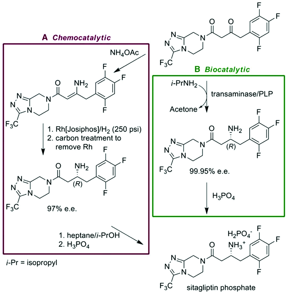 | ||
| Fig. 5 Comparison of Merck's chemocatalytic and Biocatalytic syntheses for their antidiabetic drug Sitagliptin. Reprinted with permission from AAAS.106 | ||
Accompanying unit operations
As the previous section demonstrates, tremendous strides have been achieved in the capabilities of flow syntheses. However, to integrate this technology into an end-to-end continuous production, more work must be completed regarding the peripheral unit operations that extract, separate, isolate and purify the compound of interest. Operations such as solvent exchange and in-line concentration become more complex in a continuous process.108 While by-products and unconsumed reagents can be removed by immobilized scavengers or sacrificial reagents, accumulative dilution and subsequent reaction solvent compatibility are two of the most important considerations when designing a multi-step continuous synthesis.60,108 The miniaturization of distillation columns, mixer-settlers, and falling film evaporators has been demonstrated, but few of these have so far been implementation in multi-step syntheses.109,110 Close collaboration between chemists, chemical engineers, and mechanical engineers is essential to transition these unit operations to small-scale continuous operations.Extraction/separation
Traditional manufacturing-scale separations suffer from being some of the most energy demanding unit operations, with distillations being the largest contributor.110 The introduction of less energy-intensive small-scale continuous separations could demonstrate a “Green” niche for continuous manufacturing, not only for energy minimization but also waste reduction. The automation and implementation of small-scale gravity-based liquid/liquid separations was successfully demonstrated by Ley et al.111 Typical monitoring relies on either the difference in capacitance of the aqueous and organic phase to initiate the draining of the bottom phase by the opening of a valve, or using a web camera and a reference object that sits at the interface of the two liquids.Though elegant, this methodology requires calibration for each reaction stream and delays caused by settling times and dead volumes during start-up. Recent publications have demonstrated that the use of standard rotary evaporators in a semi-continuous setup can be used to concentrate, precipitate and re-dissolve reaction products.112,113
Microfluidic devices implementing mixer-settlers, or supercritical fluids have recently been demonstrated to extract organic reagents from aqueous solutions.114,115 Due to the dominance of surface forces at this scale, they present possible alternatives for achieving efficient extractions. De-emulsification is a process concern in standard extraction processes as emulsions can be stable and persist for extended periods. Utilizing this dominance of surface forces in plate-like microchannels enables the rapid de-emulsification of two liquids.116–118 Use of capillary separators has been realised with a wide range of substrates and wetted materials.119,120
Chemically inert membranes, e.g., polytetrafluoroethylene (PTFE) can be used to selectively extract, separate and isolate the target API during or after a synthesis due to selective wettability properties. They have found widespread use in multi-step reaction sequences.121–124 These membrane units require some initial optimization dependent on the content of the reaction stream, as they exploit the difference in surface tension between the aqueous and organic phase, but once optimized, these systems offer a truly continuous methodology to complement the continuous flow synthesis of the API.125 With minimal energy requirements and the use of cheap and disposable materials, the membrane-based phase separation is a robust and Green unit operation that takes a shift towards a fully continuous methodology for the purification and separation of API reaction streams (G1, G6).
Pervaporation
Pervaporation is another membrane-separation process technology that has yet to see mainstream implementation in the pharmaceutical arena in part due to its less commercial maturity compared to more conventional separation techniques like distillation.126 Commercial success of pervaporation has been demonstrated through the recovery of organic solvents (such as isopropanol) from process waste streams, or the continuous processing of commodity chemicals, such as ethanol.127–130 Another potential use of pervaporation is the dehydration of API streams in a multi-step continuous process. High water levels can be detrimental to many chemical reactions, e.g., Grignard or lithiation reactions. Hence, if one wishes to install a late stage moisture sensitive reagent into a telescoped synthesis, there are few in-line routes available to researchers. Pervaporation's ability to break solvent azeotropes, in particular, makes it an attractive option for the dehydration of water sensitive process streams.131Applications of pervaporation are limited by chemical compatibility of current pervaporation membranes. Multiple consecutive units or recycling loops are a common feature of pervaporation setups to ensure adequate moisture removal, but they add processing time and cost. Utilizing vapour permeation, a variant of pervaporation can be applied when the reaction stream composition allows it. A hybrid vapour permeation-distillation unit where the steam from the distillation is fed to the vapour permeate unit has found extensive applications and could prove beneficial for the dehydration of flow streams.132
In-line concentration
Accumulative dilution is an inherent challenge for researchers designing telescoped multi-step syntheses. The most obvious, yet not always easiest solution is to simply start with more concentrated reagent streams. At high concentrations, solubility becomes an issue, as does the strain on the pumps that may have to run neat chemicals to obtain the desired downstream concentration. As mentioned previously, rotary evaporators may be used in a semi-continuous manner to increase stream concentration.112 Analogous to the previous unit operations, miniaturized evaporators suffer from poor chemical compatibility, low flow rates, and low diversity of solvent stream compositions. Deadman et al., successfully designed a prototype in-line evaporator to decouple the rate of removal of solvent from its boiling point.133 The system was capable of removing low to medium boiling point solvents (T < 100 °C), with high boiling solvents like water, DMF, or n-BuOH being cumbersome to remove. At 80 °C, removal of the above solvents were 32%, 56% and 86% respectively. Solvent switching was accomplished employing this prototype (MeOH/Toluene) along with the removal of excess nitromethane, a process reagent that was inhibitory to the subsequent Michael addition reaction.Solids handling
Specific chemical transformations mandate the introduction of solid reagents to a process stream, e.g., magnesium turnings for a Grignard reagent. This can be realised through the use of a continuous stirred tank reactor (CSTR) and the slow addition of material to a continuous stream, as demonstrated by researchers in Eli Lilly.134 The pumping of magnetically stirred slurries has been reported, however particle settling and potential clogging adds process risk.135 The use of mechanical feeders, i.e., hoppers or screw feeders similar to equipment used for solid formulation, could also be implemented for solids addition. Further investigation is warranted.Solids formed during a reaction is of concern for processing as the gradual deposition of solids on reactor walls can lead to increased pressure drops and ultimately channel clogging.136 Issues with process safety and product quality arise during such events. Particles formed in the process stream due to low solubility agglomerate and eventually clogs reactor tubes. Process design (e.g., avoiding sharp corners, introducing pressure pulses) and control of process parameters help mitigate clogging events. The use of fluoropolymer tubing helps prevent solids deposition onto reactor walls, and the periodic replacement of tubing is a typical operating procedure. CSTRs have been utilized in the pharmaceutical industry for continuous crystallization or for synthetic pathways known to form solids.137,138 Sonicators, e.g., haptic motors or ultrasonic probes, help mitigate clogging events.139 Other options for researchers include mechanically agitated millireactors (Coflore), the Multijet Oscillating Disk (MJOD) reactor, the Continuous-Oscillatory Baffled Reactor (COBR) or gas–liquid segmented flow.140–142 As of yet, no method has achieved widespread adoption.
Crystallization
An end-to-end process will require API to be isolated, purified, and passed onto the drug product phase of processing. It is a critical phase of manufacturing as the crystallization conditions will typically govern product purity and physical attributes of API, e.g. particle size and morphology.143,144 These material attributes can have a significant influence on downstream processing and therefore need to be managed during the crystallization phase.145 Due to their sensitivity to parameters such as temperature, mixing, and residence time, crystallizations have proved to be one of the more difficult unit operations to transition to continuous. As they are typically the last stage before formulation, it is necessary to have a process that can consistently achieve the desired purity and material attributes, i.e., avoid uncontrolled variance in process performance and quality.146 Similar to other process steps, one can envisage a strong reliance on PAT monitoring to verify process control. Continuous crystallizations can offer considerable advantages of reduced capital expenditure (CapEx) and operational expenditure (OpEx) along with the more efficient use of energy and materials (G6).147–149Continuous crystallizations offer a number of potential advantages for API attributes:
• Elimination of batch to batch variability
• Particle size control for more consistent slurry and powder properties
• Improved drying, filtration, dissolution and bulk flow properties
• Scalability of processes
In operational terms, mixed suspension mixed product removal (MSMPR), COBR, CSTR or plug flow reactors (PFR) cover the majority of platforms currently implemented for continuous crystallizations.141,148,150–155 Chemical inertness and compatibility is again a key design feature, along with concerns of fouling or encrustation of reactor walls, propellers, mixers etc. Examples of a reconfigurable continuous crystallization process train will be discussed in the case study section of the review. For more technical insights and examples, Khinast et al., provide an excellent summary of this topic.146
Analogous to its synthesis counterpart, PAT will be integral to the successful integration of continuous crystallizations downstream. At this stage of the process, researchers have many options available to them: FTIR, near-infrared spectroscopy (NIR), Raman, focused beam reflectance measurement (FBRM), and particle vision measurement (PVM) to name the main techniques (Fig. 6). Essential for real-time process monitoring and control, a suite of PAT has the potential to be applied to continuous crystallizers for monitoring of concentration, particle size distribution (PSD), and crystal morphology.156–158
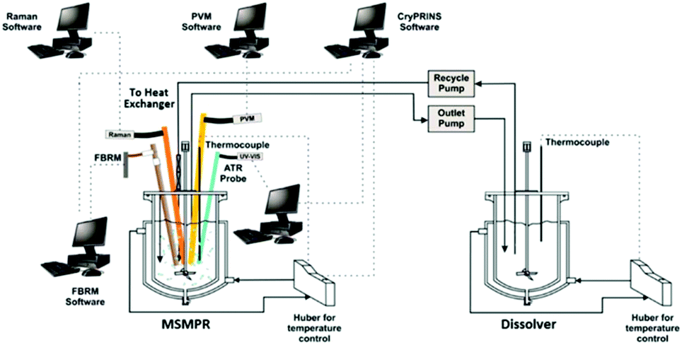 | ||
| Fig. 6 Schematic of a single-stage MSMPR unit with integrated PAT array and tools used for process monitoring and implementation of temperature control. Adapted with permission from ref. 158. Copyright (2016) American Chemical Society. | ||
Looking towards the future, despite the advances in continuous crystallization platforms, underlying fundamentals of crystallization (nucleation, growth, polymorphism, and crystal structure–property relationships) are still relatively poorly understood. As such, there is a disparate gap between the advances made and new capabilities of flow chemistry compared with continuous crystallizations. Similar to preceding unit operations, basic research efforts need to be ramped up to enable the full embrace of continuous manufacturing, if one is to produce an integrated process train for drug substance successfully.
Additional process considerations
Risk assessments for continuous
Although great strides in the field of continuous manufacturing have been achieved, it is important not to lose focus on the end goal, i.e. the integration and subsequent approval of these methodologies by regulatory agencies.19 Thus, focus on process robustness and product quality is essential. Hazards identified for a continuous manufacturing process differ from their batch counterparts and therefore, understanding the associated risks of continuous manufacturing will be of critical importance. Key elements for continuous manufacturing risk management will be process understanding and dynamics, state of control (in particular the detection and handling of deviations and disturbances in real time), real-time release testing, and control strategy verification. The adaption of QbD principles to continuous manufacturing for the understanding of the impact of process parameters and material attributes to product quality will be important.159,160Most continuous manufacturing platforms allow for the adoption of increased levels of controls, such as set points and alarms, in-process monitoring, process control and material diversion. The control strategy should incorporate these additional functionalities and be able to assure process performance and product quality.
The use of microflow based-process intensification with respect to cost- and life-cycle based optimization has recently been reported on for a number of model API. Lee et al. for 4-D-Erythronolactone and Ott et al., demonstrate the Green benefits of completing a Life-Cycle Assessment (LCA) study for a Sanofi produced API.161–164 In the study of 4-D-Erythronolactone, at the pilot plant stage it was found that wash mass intensity was significantly larger in the batch process compared to its continuous counterpart (Fig. 7). Unfortunately, this improvement was only confined to this scale. At the process level, the continuous process had a higher PMI due to more reagents being used and also more diluted reagents having to be implemented. However, overall the continuous process is seen as the “greener” process with a lower cumulative mass intensity versus the batch process.163
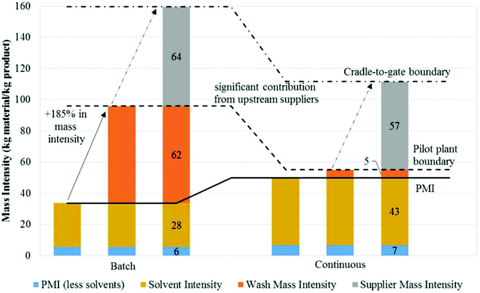 | ||
| Fig. 7 Use of Green Chemistry metrics to analyze batch & continuous processing systems. The mass intensities presented are calculated using base case values. The bolded line denotes PMI, while the dotted line denotes the mass intensity at the pilot plant level. The dash-dotted line denotes the Cradle-to-Gate (CtG) boundary and indicates the cumulative mass intensity.163 Copyright (2016) American Chemical Society. | ||
The Hessel lab recently reported on a feasibility study for the step by step batch to flow conversion of the synthesis of rufinamide. A reduction of 756 kg CO2 equivalents per kg API was achieved.164 An average reduction of 45% for all life cycle impact assessment (LCIA) potentials was found for the transition from multistep batch to multistep flow.164 Among their metrics for process improvement were PMI, cumulative energy demand (CED) and solvent rate. This comes with the caveat of need for development of continuous operations like solvent switches, in-line concentration etc. to address solvent compatibility or orthogonality. Work like this provides an accessible roadmap for researchers interested in conducting an environmental assessment and optimization study of different viable pathways.
Cleaning
Cleaning is a critical aspect of pharmaceutical manufacturing governed by Federal Regulations (CFR, Part 211.67). It mandates that equipment be cleaned prior to manufacturing to prevent adulteration or contamination of products.165–167 Within organisations, these protocols are often seen as time- and resource consuming activities that add to operational costs of product manufacturing. The introduction of in-line PAT as a method for continuous real-time analysis leads to a more efficient release of cleaned equipment.168,169 Similar to the transitioning of other unit operations to continuous, a reassessment and/or adaptation of cleaning protocols and methodologies will be required. These “new” cleaning protocols will feed into the risk assessment and the life cycle approach implemented by the individual pharmaceutical companies.The redundancy of large batch reactors (as discussed above) provides an opportunity for the reduction in cleaning solvents and thus, the volume of waste generated (G1). The utilization of perfluoroalkoxy (PFA) tubular reactors allows for a certain degree of flexibility with regard to treating these as “disposable”, plug and play type systems, negating the need for cleaning. Thus, multiple components of continuous manufacturing can work in parallel (decreased reactor volumes, PAT monitoring, and PFA tubing) to facilitate waste reduction.
Economic assessment of continuous
Economic assessment of continuous manufacturing is difficult as there are only sparse examples of integrated end-to-end equipment trains. However, a review exploring continuous processing opportunities for the pharmaceutical industry would be remiss not to mention the economic impact this transition to continuous manufacturing can have based on the Novartis-MIT collaboration. In this first example of an integrated continuous manufacturing plant, researchers constructed a shipping size container (2.4 × 7.3 m3) platform capable of late-stage synthetic transformations and subsequent separations, crystallizations, drying and final formulation to yield United States Pharmacopeia (USP)-spec tablets of aliskiren hemifumarate at 2.7 × 10⁶ tablet per year.170 Although individual differences between batch and continuous processing have been studied, an analysis of the continuous manufacturing of a late-stage intermediate to final dose had yet to be published.171–174 With detailed expenditure analysis provided by Novartis on the batch process, an economic assessment of the respective methods of manufacturing this API was realised.149CapEx for this project was estimated to be 20–76% lower, depending on a number of factors, such as key intermediate cost and drug loading. OpEx were between 40% lower and 9% lower, again depending on factors like drug loading etc. A recycling step integrated into the process, coupled with a novel direct tablet formation process yielded the greatest estimated savings, i.e., between 9 to 40%. Savings in materials handling and CapEx can compensate for a 10% reduction in yield by the continuous process. Labour and plant footprint are two obvious areas of cost savings inherent to continuous processing. Smaller processing equipment and energy savings on heating, ventilation, and air conditioning accompanied by reduced transportation of material between units, quality control/quality assurance (QC/QA), and in-process inventory can all see significant reductions with a move to continuous manufacturing.171,173,174
Commensurate with the above findings, Schaber et al., report a 58% CapEx and 67% OpEx annual savings for a continuous pharmaceutical processing facility versus a batch processing facility.149 One caveat is that initial process development costs associated with continuous manufacturing processing as opposed to the batch process will tend to be higher because of the complexity.170 On the other hand, the continuous manufacturing development also gains increased process understanding, on-line instrumentation (i.e., PAT) and the role of process control and real-time release. Small-scale flow platforms as alluded to previously offer the ability to gain large amounts of data with low experimental load, reducing the learning curve. This increase in process understanding at the development stage will facilitate straightforward paths to scale-up, which likely will lead to CapEx and OpEx savings (labour costs will typically be lower once the process is operational).
Case studies
Case study 1: The F3 initiative
The F3 (Flexible, Fast, and Future) project conducted over 4 years and costing 30 million euro, provides an example of an academic/industry collaborative research effort to create modular, flexible platforms that enable more efficient strategies towards product development.175 Over 300 scientists, engineers, PhD students, business and academic experts engaged in the project. Building off several industrial case studies, this “plug and play” modular design demonstrated this concept at industrial scale for commercial applications and achieved validation of new reactor technologies and new intensified continuous processes (Fig. 8).176 From a Green Chemistry standpoint, this project showcased many of the desirable attributes of continuous manufacturing. Researchers working on the production of drugs, polymers and surfactants were able to achieve significant solvent reductions, reduced energy consumption up to 30%, and a footprint reduction of up to 50%.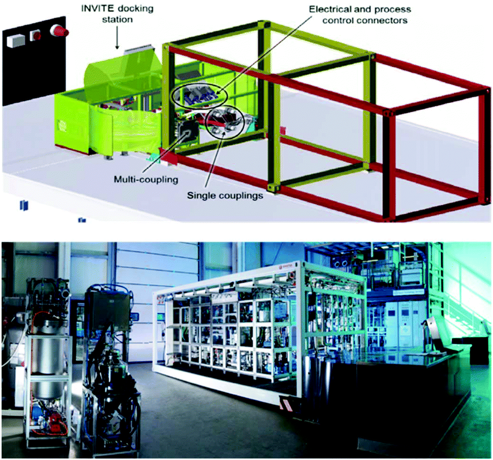 | ||
| Fig. 8 Conceptual representation of the F3 system (left) and manufactured version of the flexible mobile factory (right).177 | ||
A theme across all F3 case studies was the introduction of new miniaturized technology, e.g. micro-structured reactor plates that could be used in a plug and play manner within a mobile process equipment container (PEC) and finally validation of each new methodology. Their proof of concept hydroformylation, partial oxidation, and epoxidation reactions demonstrated the capabilities of the ISO container unit, however, the material of construction could prove troublesome when translating this methodology to more complex and aggressive chemistries.
The Bayer Technology Services (BTS) group, in conjunction with university researchers, wished to assess the potential to replicate the quality, efficiency, resource consumption, and cost reductions associated with large-scale continuous API manufacturing in a modular flexible container-based production unit. The researchers successfully operated the process sequence for several days. The results from this “production” run demonstrated the multitude of CapEx and OpEx reductions one is now accustomed to with continuous manufacturing, e.g. reductions in starting material costs, apparatus cost (∼30%), and reduction in both reaction and processing time.173
Continuous manufacturing under cGMP conditions
Eli Lilly, an early adopter of continuous manufacturing, has recently published a kilogram-scale synthesis of a drug in their pipeline under continuous-flow cGMP conditions.112 Prexaseritib monolactate, a checkpoint kinase 1 inhibitor is being investigated in Phase 1b and 2 clinical trials in combination cytotoxic chemotherapy, targeted agents, and as a monotherapy. The drug is administered via infusion due to low oral bioavailability and thus, aqueous solubility is desirable for the drug substance. A previously designed nine-step process was deemed unsuitable from a business and technical standpoint. Hazardous reagents and suboptimal bond disconnections were some of the primary drivers for the switch to a continuous process (G3, G5). Eight-unit operations (continuous reactors, extractors, evaporators, crystallisers etc.) contained within laboratory fume hoods enabled the development of a multistep continuous-flow cGMP process that produced 24 kilograms (roughly three kg day−1) of prexaseritib monolactate suitable for human clinical trials (G6).This example not only illustrated continuous manufacturing under cGMP conditions, but also demonstrated the important mantra of “continuous where appropriate”. The first four steps of the process were conducted in batch mode to afford nitrile 6, the starting material for the cGMP continuous sequence (four steps). From Scheme 2, it is immediately clear the driver for operating “Step 1” in flow (G3, G12). Elevated temperature and pressures, in association with hydrazine as a reagent, are conditions that are not conducive to safe operating parameters in batch mode. Waste production was minimized through the complete forward processing of all the reactor flow due to the negligible impact of dilute impurities in the downstream extraction system (G1).
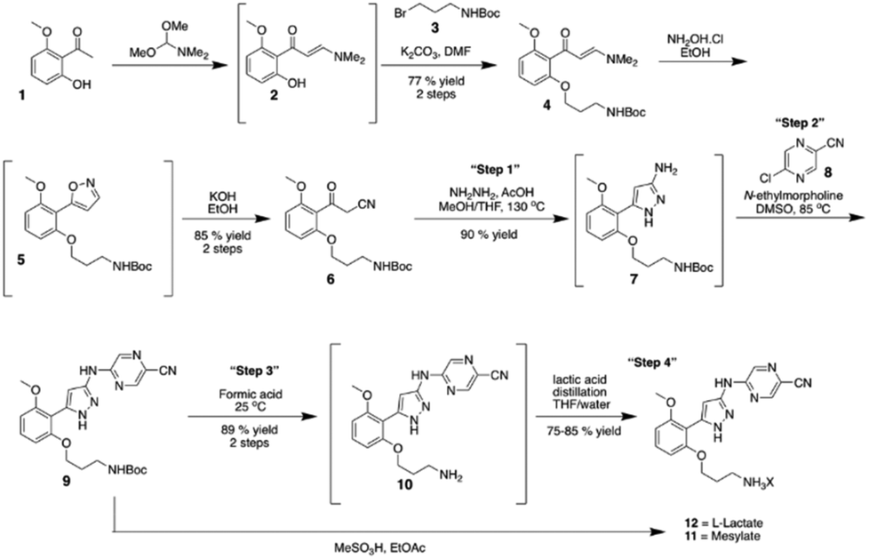 | ||
| Scheme 2 Continuous manufacturing production route for prexaseratib monolactate monohydrate under cGMP conditions.112 Reprinted with permission from AAAS. | ||
A separation, washing, and counter-current extraction was implemented to yield 7 while controlling the level of hydrazine to <2 parts per million relative to 7. Avoiding the isolation of 7 had numerous benefits; not only did it increase the yield and minimize the waste produced (G1), it allowed for minimal operational exposure (compound 8 had tested positive in an Ames mutagenicity assay) (G12).
An automated 20-liter rotary evaporator was implemented to concentrate the reaction through the removal of THF, methanol, toluene and water.178 This semi-continuous unit operation proved to be a more attractive option over other evaporator types as it was also required in a later step of the process, thus reducing the overall equipment cost. A batch process solvent strip for “step four” was deemed inefficient due to the inability of a tank reactor to achieve the thin film obtained in a rotary evaporator. Elevated impurity levels were observed over extended processing times. Therefore, the reaction stream was concentrated using the automated rotary evaporator module and immediately diluted with THF before transfer to a surge vessel. The process concluded with a batch crystallisation as timing constraints had not allowed for the complete development of a continuous crystallisation that could sufficiently mitigate the risk of salt form contamination and other known areas of concern.
As discussed above, PAT and continuous manufacturing work in concert to provide real-time process information and help demonstrate a state of control. Online PAT was heavily used in this example to characterise and monitor the process. Although the authors’ on-line HPLC was used “for information only”, i.e., could not be used for cGMP decision making, they do demonstrate the value of having process monitoring tools in place. The on-line HPLC detected a disturbance several days into manufacturing and the root cause of the disruption was discovered and an adequate solution was efficiently implemented. This real-time availability prevented the production of out of specification material that may have gone unnoticed in batch manufacturing until off-line HPLC analysis. This batch would have necessitated reworking or, in the worst-case scenario, disbandment to waste (G1).
Another manufacturing scale example of the Green virtues of continuous manufacturing completed by Lilly was their high-pressure hydrogenation which they completed in their Kinsale, Ireland plant in 2013.179 Through the use of a pipe-in-series reactor housed outside of the building, the process could be classified as a low-risk operation (G12). Concurrently, the use of an iridium catalyst avoids the requirement of a stoichiometric charge of the reducing agent sodium triacetoxyborohydride (STAB) (equivalent to 1.2 million kg over the lifetime of the product), thereby dramatically reducing the cost and waste associated with this reaction (Fig. 9) (G9).
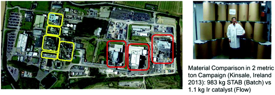 | ||
| Fig. 9 (Left) Lilly manufacturing plant in Kinsale, Co. Cork, Ireland with the respective footprints of their biological manufacturing in (red), small molecule (yellow) and the small-volume continuous (SVC) (blue). (Right) Comparison of the quantity of material required for two different reducing agents required for a high-pressure hydrogenation.179 | ||
These industrial-scale examples epitomize the current state of the art of continuous manufacturing and demonstrate the ability to implement multiple unit operations in a continuous/semi-continuous fashion under cGMP conditions. Green Chemistry principles are demonstrated throughout, in particular: waste reduction, better atom economy, safer chemistry for accident prevention, and energy efficiency.
Case study 3: Pharmacy on demand (POD)
The DARPA funded ‘Battlefield Medicines’ initiative wished to leverage the advances made in continuous processing and develop a flexible, miniaturized synthesis and manufacturing platform. This platform would enable the effective small-batch pharmaceutical production of multiple APIs in the one mobile, reconfigurable unit.86 This on demand manufacturing could potentially reduce the complexity of supply chains, drug market forecasts, and, finally, obviate the stockpiling of individual drugs. The end-to-end continuous manufacturing of the API aliskiren hemifumarate in a shipping sized container by the MIT-Novartis center for continuous manufacturing served as an introduction to the paradigm of continuous manufacturing of pharmaceuticals for the team.170 Lessons learned from this project allowed for the redesign of a modular system that was ∼1/40 the size due to the construction of compact chemical reaction and purification equipment.Complex multistep synthesis, multiple in-line purifications, post-synthesis workups (extractions etc.) and crystallizations can be executed under real-time process monitoring conditions in a refrigerator-sized platform [1.0 m (width × 0.7 m (length) × 1.8 m (height), ∼100 kg] (Fig. 10). To demonstrate the capabilities of this proof of concept, four API were selected from the World Health Organization (WHO) list of essential medicines. Generic drugs, which would also typically be found in a chief medic's toolkit. Diphenhydramine hydrochloride, diazepam, lidocaine hydrochloride, and fluoxetine hydrochloride provided a spectrum of different drug classes, with varying molecular complexity. Thus, a variety of synthetic pathways are required to obtain these drugs and showcase the generality of the platform. Once synthesized, these crude solutions were further processed through sequential batch precipitation and crystallization unit operations to yield the isolated API. This API was then formulated into the corresponding liquid dosage form.
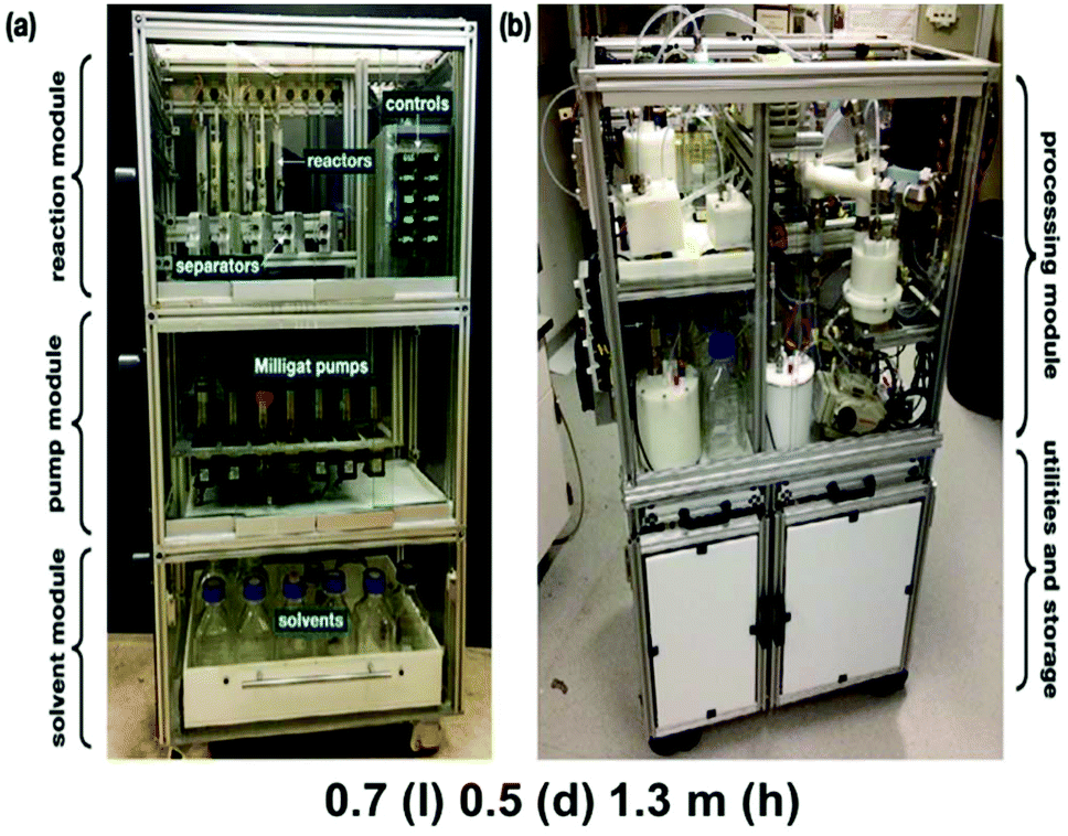 | ||
| Fig. 10 Units designed for the pharmacy on demand initiative, phase two. Reprinted with permission from Wiley & Sons.180 | ||
The next-generation derivative of these manufacturing units involved a 25% reduction in size while adding increased processing capabilities.180 For the synthesis unit, this was achieved through the use of modified compact Milligat pumps (21 pumps), a bookshelf reactor holding bay (12 reactors), and greatly simplified control unit that is run off LabVIEW. Liquid–liquid separators and in-line evaporators were added as additional unit operations. These new units allowed for the continuous extraction/separation of reaction streams as well as the in-line concentration of the reaction stream. The downstream purification unit operated a precipitation unit, batch and continuous crystallization units, and a formulation/feed tank unit for the final liquid formulation. Automation of their processes was again achieved primarily through LabVIEW. The pressure-driven flow was utilized in this generation to accomplish single or two-stage continuous crystallizations in the custom jacketed vessels.
To complement the successful utilization of these systems, a portable, re-configurable and automated system for on-demand tablet manufacturing was designed and manufactured to increase the scope of the final output to include solid dosage forms.181 This tableting unit was seen as an essential iterative step for the realization of these technologies for the on-demand production of pharmaceuticals. Its capability of producing hundreds to thousands of tablets per day, presented the opportunity for a “make it and take it” paradigm that could help limit the overproduction of API and thus reduce chemical usage and concomitantly reduced waste formation (G1).
Miniaturized platforms like PoD have the potential to scale-up or scale-out with relative ease in times of fluctuating market demands. The end-to-end continuous manufacturing of API in such a manner means the reduction in solvent volumes and waste generated, energy usage and other benefits of process intensification (vide supra) are possible, entwining them with a litany of the principles of Green manufacturing (G1, G2, G5, G6, G8, G9, G11, G12).
Conclusions
A tally of the occurrences of the principles of Green Chemistry throughout the piece reveals that the principle of prevention greatly overshadows all other principles (Fig. 11). This should not come as a surprise as prevention of waste from occurring, be it chemical, financial or time is a far more attractive option than having to treat or clean it once produced. When implemented correctly, continuous manufacturing has the potential to reduce the time to market through accelerated process intensification and scale up work. Concomitant with this reduction in time, reductions in synthetic steps, reagents and solvent consumption and power consumption all aid increase the potential Green footprint.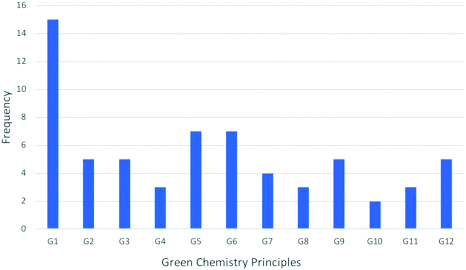 | ||
| Fig. 11 A chart demonstrating the frequency of the principles of Green Chemistry throughout the article. | ||
Some principles may not be as apparent (G3, G4, G7, G10), but successful integration of continuous unit operations, where appropriate, will have a positive Green impact for the academic lab or pharmaceutical company implementing them. The FDA has attempted to encourage continuous processing by releasing documents such as the guidance documents mentioned previously.40,41,52 Industry sentiment seems to lie on the side of caution and perhaps one can begin to divide companies into those who wish to be champions of this emerging technology and those who take a wait-and-see approach.
In 2008, Roberge et al., asked the question, “Is the continuous revolution underway for the Pharmaceutical Industry?”172 They highlighted the need for a generalized adoption by the ‘Big Players’ in the industry. Eleven years on, significant strides have been achieved in technologies for the continuous manufacturing of drug substance and drug product. Pharmaceutical companies have completed successful submissions of processes that contain continuous steps, which can be seen as a great accomplishment for the field, but there are still more opportunities for realizing Green continuous processes.
Conflicts of interest
There are no conflicts to declare.Acknowledgements
This work was supported in part by the Defence Advanced Research Project Agency (DARPA) under Contract No. N66001-16-C-4005.Notes and references
- S. V. Ley, D. M. Mynett and W.-J. Koot, Synlett, 1995, 1017–1020 CrossRef CAS.
- I. R. Baxendale and S. V. Ley, Bioorg. Med. Chem. Lett., 2000, 10, 1983–1986 CrossRef CAS PubMed.
- R. A. Sheldon, Chem. Soc. Rev., 2012, 41, 1437–1451 RSC.
- ACS Green Chemistry white paper, https://www.acs.org/content/dam/acsorg/membership/acs/benefits/extra-insights/green-chemistry-applications.pdf, (accessed April 2019).
- H. C. Erythropel, J. B. Zimmerman, T. M. de Winter, L. Petitjean, F. Melnikov, C. H. Lam, A. W. Lounsbury, K. E. Mellor, N. Z. Janković, Q. Tu, L. N. Pincus, M. M. Falinski, W. Shi, P. Coish, D. L. Plata and P. T. Anastas, Green Chem., 2018, 20, 1929–1961 RSC.
- B. M. Trost, Science, 1991, 254, 1471–1477 CrossRef CAS PubMed.
- M. B. Gawande, V. D. B. Bonifácio, R. Luque, P. S. Branco and R. S. Varma, ChemSusChem, 2014, 7, 24–44 CrossRef CAS PubMed.
- P. Anastas and N. Eghbali, Chem. Soc. Rev., 2009, 39, 301–312 RSC.
- J. H. Clark, Green Chem., 1999, 1, 1–8 RSC.
- A. Albini and S. Protti, Paradigms in Green Chemistry and Technology, Springer, 2015 Search PubMed.
- V. Polshettiwar and R. S. Varma, Chem. Soc. Rev., 2008, 37, 1546–1557 RSC.
- B. P. Mason, K. E. Price, J. L. Steinbacher, A. R. Bogdan and D. T. McQuade, Chem. Rev., 2007, 107, 2300–2318 CrossRef CAS PubMed.
- S. G. Newman and K. F. Jensen, Green Chem., 2013, 15, 1456–1472 RSC.
- S. Falß, N. Kloye, M.L. Holtkamp, A. Prokofyeva, T. Bieringer and N. Kockmann, in Handbook of Green Chemistry, Green Chemical Engineering, Wiley Online Library, 2019, vol. 12, DOI:10.1002/9783527628698.hgc139, (accessed April 2019).
- R. A. Sheldon, ACS Sustainable Chem. Eng., 2018, 6, 32–48 CrossRef CAS.
- C. Jimenez-Gonzalez, C. S. Ponder, Q. B. Broxterman and J. B. Manley, Org. Process Res. Dev., 2011, 15, 912–917 CrossRef CAS.
- R. A. Sheldon, Green Chem., 2007, 9, 1273–1283 RSC.
- R. A. Sheldon, Green Chem., 2017, 19, 18–43 RSC.
- X. Yang, D. Acevedo, A. Mohammad, N. Pavurala, H. Wu, A. L. Brayton, R. A. Shaw, M. J. Goldman, F. He, S. Li, R. J. Fisher, T. F. O'Connor and C. N. Cruz, Org. Process Res. Dev., 2017, 21, 1021–1033 CrossRef CAS.
- C. S. Slater, M. J. Savelski, W. A. Carole and D. J. C. Constable, in Green Chemistry in the Pharmaceutical Industry, ed P. J. Dunn, A. S. Wells and M. T. Williams, Wiley-VCH, Weinheim, Germany, 2010, ch. 3, pp. 49–81 Search PubMed.
- D. J. C. Constable, C. Jimenez-Gonzalez and R. K. Henderson, Org. Process Res. Dev., 2007, 11, 133–137 CrossRef CAS.
- C. Jiménez-González, A. D. Curzons, D. J. C. Constable and V. L. Cunningham, Clean Technol. Environ. Policy, 2004, 7, 42–50 CrossRef.
- EPA Green Chemistry Challenge Winners, https://www.epa.gov/Greenchemistry/presidential-Green-chemistry-challenge-winners, (accessed April 2019).
- C.-W. Cho, T. P. T. Pham, Y.-C. Jeon and Y.-S. Yun, Green Chem., 2008, 10, 67–72 RSC.
- P. Pollet, E. A. Davey, E. E. Ureña-Benavides, C. A. Eckert and C. L. Liotta, Green Chem., 2014, 16, 1034–1055 RSC.
- M. C. Bubalo, S. Vidović, I. R. Redovniković and S. Jokić, J. Chem. Technol. Biotechnol., 2015, 90, 1631–1639 CrossRef.
- J. A. DiMasi, R. W. Hansen and H. G. Grabowski, J. Health Econ., 2003, 22, 151–185 CrossRef PubMed.
- C. Jiménez-González, P. Poechlauer, Q. B. Broxterman, B.-S. Yang, D. Ende, J. Baird, C. Bertsch, R. E. Hannah, P. Dell'Orco, H. Noorman, S. Yee, R. Reintjens, A. Wells, V. Massonneau and J. Manley, Org. Process Res. Dev., 2011, 15, 900–911 CrossRef.
- J. Khinast, J. Rantanen, R. Steiner and M. Jornitz, Continuous Processing in the Pharmaceutical Industry: Status and Perspective, in Continuous Manufacturing of Pharmaceuticals, ed. P. Kleinebudde, J. Khinast and J. Rantanen, 2017, DOI:10.1002/9781119001348.ch11.
- Vertex Case Study. Available from: http://www.gea.com/global/en/stories/vertex-case-study.jsp, (accessed April 4, 2019).
- D. E. Smith, Quality by Design (QbD) for the Continuous Manufacturing of Solid Oral Dosage Forms. Available from: http://pqri.org/wp-content/uploads/2015/11/Embiata-Smith.pdf, (accessed April 2019).
- FDA Approves Tablet Production on Janssen Continuous Manufacturing Line. Available from: http://www.pharmtech.com/fda-approves-tablet-production-janssen-continuous-manufacturing-line, (accessed April 2019).
- M. Warman, Control Strategy in Continuous Manufacturing of Drug Product, Presentation at IFPAC, Washington, DC, USA, 2014 Search PubMed.
- A. Witty, Glaxo Use New Technology at India Plant, 2013, Available at: http://www.fiercephar mananufacturing.com/story/glaxo-use-new-technology-india-plant/2013-11-18, (accessed 2 February 2016).
- Pharmaceutical Online, https://www.pharmaceuticalonline.com/doc/how-gsk-launched-a-continuous-manufacturing-pilot-plant-and-what-it-learned-0001?vm_tId=2013612&user=7af6e7b1-db3c-46ed-8fac-e02218d89cba&sthash.4tAReGcq.mjjoJ, (accessed April 2019).
- Zeton Homepage http://www.zeton.com/site/news.html, (accessed April 2019).
- S. Gloss and S. Heidel, Small-scale Process Design to Facilitate Commercialization of a Wet Granulation Process using Continuous Manufacturing and Bringing Continuous Manufacturing to OSD, Poster presentation at AAPS, San Diego, USA, 2014 Search PubMed.
- K. Congdon, Inside Pfizer's modular manufacturing pods, http://www.pharmaceuticalonline.com/doc/inside-pfizer-s-modular-manufacturing-pods0001.
- ASTM E2968, Standard Guide for Application of Continuous Processing in the Pharmaceutical Industry, American Society for Testing and Materials, West Conshohocken, USA, 2015 Search PubMed.
- S. L. Lee, T. F. O'Connor, X. Yang, C. N. Cruz, S. Chatterjee, R. D. Madurawe, C. M. V. Moore, L. X. Yu and J. Woodcock, J. Pharm. Innovation, 2015, 10, 191–199 CrossRef.
- Draft FDA Guidance for Industry, https://www.fda.gov/ucm/groups/fdagov-public/@fdagov-drugs-gen/documents/document/ucm632033.pdf, (accessed April 2019).
- U.S., Guidance for Industry: Q8(2) Pharmaceutical Development, Food and Drug Administration, Maryland, 2009 Search PubMed.
- U.S., Guidance for Industry: Q9 Quality Risk Management, Food and Drug Administration, Maryland, 2006 Search PubMed.
- U.S., Guidance for Industry: Q10 Pharmaceutical Quality Systems, Food and Drug Administration, Maryland, 2009 Search PubMed.
- U.S., Guidance for Industry: Q8, Q9, and Q10 Questions and Answers, Food and Drug Administration, Maryland, 2011 Search PubMed.
- ICH Quality Implementation Working Group, Point to Consider: ICH-endorsed Guide for ICH Q8/Q9/Q10 Implementation, 2011 Search PubMed.
- U.S., Guidance for Industry: Q11 Development and Manufacture of Drug Substance, Food and Drug Administration, Maryland, 2012 Search PubMed.
- ICH Harmonised Tripartite Guideline: Pharmaceutical Development Q8(r2), Current Step 4 Version, in The International Conference on Harmonisation, Geneva, Switzerland, 2009.
- B. Kvarnström and B. Bergquist, Prod. Plan. Control, 2012, 23, 396–404 CrossRef.
- Y. Gao, A. Vanarase, F. Muzzio and M. Ierapetritou, Chem. Eng. Sci., 2011, 66, 417–425 CrossRef CAS.
- E. Reitz, H. Podhaisky, D. Ely and M. Thommes, Eur. J. Pharm. Biopharm., 2013, 85, 1200–1205 CrossRef CAS PubMed.
- ISCMP Regulatory White Paper, https://iscmp2016.mit.edu/regulatory-white-paper, (accessed April 2019).
- F.D.A., Guidance for Industry: PAT – A Framework for innovative pharmaceutical development, manufacturing, and quality assurance, Rockville, MD, 2004 Search PubMed.
- D. R. Snead and T. F. Jamison, Chem. Sci., 2013, 4, 2822–2827 RSC.
- C. A. Correia, K. Gilmore, D. T. McQuade and P. H. Seeberger, Angew. Chem., Int. Ed., 2015, 54, 4945–4948 CrossRef CAS PubMed.
- C.-J. Li and B. M. Trost, Proc. Natl. Acad. Sci. U. S. A., 2008, 105, 13197–13202 CrossRef CAS PubMed.
- S. V. Ley, Chem. Rec., 2012, 12, 378–390 CrossRef CAS PubMed.
- J. B. Zimmerman and P. T. Anastas, When Is a Waste not a Waste? in Sustainability Science and Engineering: Defining Principles, ed. M. A. Abraham, Elsevier Science, The Netherlands, 2006, vol. 1, pp. 201–221 Search PubMed.
- US Dept. of Energy, Quadrennial Technology Review 2015: Chapter 6 - Technology Assessments: Process Intensification, Washington, DC, 2015 Search PubMed.
- H. Lin, C. Dai, T. F. Jamison and K. F. Jensen, Angew. Chem., Int. Ed., 2017, 56, 8870–8873 CrossRef CAS PubMed.
- J. A. M. Lummiss, P. D. Morse, R. L. Beingessner and T. F. Jamison, Chem. Rec., 2017, 17, 667–680 CrossRef CAS PubMed.
- B. Martin, H. Lehmann, H. Yang, L. Chen, X. Tian, J. Polenk and B. Schenkel, Curr. Opin. Green Sustain. Chem., 2018, 11, 27–33 CrossRef.
- D. Dallinger and C. O. Kappe, Curr. Opin. Green Sustain. Chem., 2017, 7, 6–12 CrossRef.
- Syrris Website, http://www.syrris.com, (accessed Aril 2019).
- Vapourtec Website, http://www.vapourtec.com, (accessed Aril 2019).
- Ehrfeld Website, https://ehrfeld.com/home.html, (accessed Aril 2019).
- Corning Website, https://www.corning.com/media/worldwide/Innovation/documents/G4SiC_WEB.pdf, (accessed Aril 2019).
- M. Al-Rawashdeh, F. Yue, N. G. Patil, T. A. Nijhuis, V. Hessel, J. C. Schouten and E. V. Rebrov, AIChE J., 2014, 60, 1941–1952 CrossRef CAS.
- Harvard Apparatus Website, http://www.harvardapparatus.com, (accessed Aril 2019).
- Vici Website, https://www.vici.com/liqhand/m6.php, (accessed Aril 2019).
- K. F. Jensen, AIChE J., 2017, 63, 858–869 CrossRef CAS.
- M. B. Plutschack, B. Pieber, K. Gilmore and P. H. Seeberger, Chem. Rev., 2017, 117, 11796–11893 CrossRef CAS PubMed.
- C. Wiles and P. Watts, Green Chem., 2012, 14, 38–54 RSC.
- J. Britton and T. F. Jamison, Nat. Protoc., 2017, 12, 2423–2446 CrossRef CAS PubMed.
- Novartis Website, https://www.novartis.com/stories/discovery/new-drug-manufacturing-tools-change-pharma-chemistry?utm_source=linkedin&utm_medium=social&utm_campaign=2018-08-New-drug-manufacturing%20utm_medium%3Dsocial&utm_content=New-drug-manufacturing-1, (accessed Aril 2019).
- Zaiput Website, http://www.zaiput.com/?q=liquid-liquid-separators, (accessed Aril 2019).
- Zaiput Website, http://www.zaiput.com/back-pressure-regulators, (accessed Aril 2019).
- J. Yoshida, A. Nagaki and T. Yamada, Chem. – Eur. J., 2008, 14, 7450–7459 CrossRef CAS PubMed.
- M. Movsisyan, E. I. P. Delbeke, J. K. E. T. Berton, C. Battilocchio, S. V. Ley and C. V. Stevens, Chem. Soc. Rev., 2016, 45, 4892–4928 RSC.
- P. B. Balde and T. F. Jamison, Angew. Chem., Int. Ed., 2011, 50, 3525–3528 CrossRef PubMed.
- C. Wiles and P. Watts, Green Chem., 2013, 16, 55–62 RSC.
- J. Britton and C. L. Raston, Chem. Soc. Rev., 2017, 46, 1250–1271 RSC.
- J. Wegner, S. Ceylan and A. Kirschning, Adv. Synth. Catal., 2012, 354, 17–57 CrossRef CAS.
- B. Gutmann, D. Cantillo and C. O. Kappe, Angew. Chem., Int. Ed., 2015, 54, 6688–6728 CrossRef CAS PubMed.
- R. Porta, M. Benaglia and A. Puglisi, Org. Process Res. Dev., 2016, 20, 2–25 CrossRef CAS.
- A. Adamo, R. L. Beingessner, M. Behnam, J. Chen, T. F. Jamison, K. F. Jensen, J.-C. M. Monbaliu, A. S. Myerson, E. M. Revalor, D. R. Snead, T. Stelzer, N. Weeranoppanant, S. Y. Wong and P. Zhang, Science, 2016, 352, 61–67 CrossRef CAS PubMed.
- M. Baumann and I. R. Baxendale, Beilstein J. Org. Chem., 2015, 11, 1194–1219 CrossRef CAS PubMed.
- L. D. Elliott, J. P. Knowles, P. J. Koovits, K. G. Maskill, M. J. Ralph, G. Lejeune, L. J. Edwards, R. I. Robinson, I. R. Clemens, B. Cox, D. D. Pascoe, G. Koch, M. Eberle, M. B. Berry and K. I. Booker-Milburn, Chem. – Eur. J., 2014, 20, 15226–15232 CrossRef CAS PubMed.
- K. Loubière, M. Oelgemöller, T. Aillet, O. Dechy-Cabaret and L. Prat, Chem. Eng. Process., 2016, 104, 120–132 CrossRef.
- S. Josland, S. Mumtaz and M. Oelgemöller, Chem. Eng. Technol., 2015, 39, 81–87 CrossRef.
- E. N. DeLaney, D. S. Lee, L. D. Elliott, J. Jin, K. I. Booker-Milburn, M. Poliakoff and M. W. George, Green Chem., 2017, 19, 1431–1438 RSC.
- N. Hoffmann, Chem. Rev., 2008, 108, 1052–1103 CrossRef CAS PubMed.
- D. Cambié, C. Bottecchia, N. J. W. Straathof, V. Hessel and T. Noël, Chem. Rev., 2016, 116, 10276–10341 CrossRef PubMed.
- C. A. Busacca, D. R. Fandrick, J. J. Song and C. H. Senanayake, Adv. Synth. Catal., 2011, 353, 1825–1864 CrossRef CAS.
- C. S. Higman, J. A. M. Lummiss and D. E. Fogg, Angew. Chem., Int. Ed., 2016, 55, 3552–3565 CrossRef CAS PubMed.
- P. Li, J. S. Moore and K. F. Jensen, ChemCatChem, 2013, 5, 1729–1733 CrossRef CAS.
- N. Zaborenko, R. J. Linder, T. M. Braden, B. M. Campbell, M. M. Hansen and M. D. Johnson, Org. Process Res. Dev., 2015, 19, 1231–1243 CrossRef CAS.
- M. Shang, T. Noel, Q. Wang and V. Hessel, Chem. Eng. Technol., 2013, 36, 1001–1009 CrossRef CAS.
- M. Planchestainer, M. L. Contente, J. Cassidy, F. Molinari, L. Tamborini and F. Paradisi, Green Chem., 2017, 19, 372–375 RSC.
- L. Babich, A. F. Hartog, M. A. van der Horst and R. Wever, Chem. – Eur. J., 2012, 18, 6604–6609 CrossRef CAS.
- L. Tamborini, D. Romano, A. Pinto, A. Bertolani, F. Molinari and P. Conti, J. Mol. Catal. B: Enzym., 2012, 84, 78–82 CrossRef CAS.
- I. Itabaiana, L. S. de Mariz e Miranda and R. O. M. A. de Souza, J. Mol. Catal. B: Enzym., 2013, 85–86, 1–9 CrossRef CAS.
- H. Gröger, M. Pieper, B. König, T. Bayer and H. Schleich, Sustainable Chem. Pharm., 2017, 5, 72–79 CrossRef.
- A. S. Wells, G. L. Finch, P. C. Michels and J. W. Wong, Org. Process Res. Dev., 2012, 16, 1986–1993 CrossRef CAS.
- U. T. Bornscheuer, G. W. Huisman, R. J. Kazlauskas, S. Lutz, J. C. Moore and K. Robins, Nature, 2012, 485, 185–194 CrossRef CAS PubMed.
- C. K. Savile, J. M. Janey, E. C. Mundorff, J. C. Moore, S. Tam, W. R. Jarvis, J. C. Colbeck, A. Krebber, F. J. Fleitz, J. Brands, P. N. Devine, G. W. Huisman and G. J. Hughes, Science, 2010, 329, 305–309 CrossRef CAS PubMed.
- M. Heidlindemann, G. Rulli, A. Berkessel, W. Hummel and H. Groger, ACS Catal., 2014, 4, 1099–1103 CrossRef CAS.
- T. A. Hamlin, G. M. L. Lazarus, C. B. Kelly and N. E. Leadbeater, Org. Process Res. Dev., 2014, 18, 1253–1258 CrossRef CAS.
- A. Ziogas, V. Cominos, G. Kolb, H.-J. Kost, B. Werner and V. Hessel, Chem. Eng. Technol., 2012, 35, 58–71 CrossRef CAS.
- D. S. Sholl and R. P. Lively, Nature, 2016, 532, 435–437 CrossRef PubMed.
- M. O'Brien, P. Koos, D. L. Browne and S. V. Ley, Org. Biomol. Chem., 2012, 10, 7031–7036 RSC.
- K. P. Cole, J. M. Groh, M. D. Johnson, C. L. Burcham, B. M. Campbell, W. D. Diseroad, M. R. Heller, J. R. Howell, N. J. Kallman, T. M. Koenig, S. A. May, R. D. Miller, D. Mitchell, D. P. Myers, S. S. Myers, J. L. Phillips, C. S. Polster, T. D. White, J. Cashman, D. Hurley, R. Moylan, P. Sheehan, R. D. Spencer, K. Desmond, P. Desmond and O. Gowran, Science, 2017, 356, 1144–1150 CrossRef CAS PubMed.
- E. McManus, Design and implementation of a small foot-print continuous API facility for portfolio commercialization, 2016 FDA-AIChE workshop on adopting continuous manufacturing, 2016 Search PubMed.
- M. N. Kashid, Y. M. Harshe and D. W. Agar, Ind. Eng. Chem. Res., 2007, 46, 8420–8430 CrossRef CAS.
- N. Assmann, S. Kaiser and P. Rudolf von Rohr, J. Supercrit. Fluids, 2012, 67, 149–154 CrossRef CAS.
- Y. Okubo, M. Toma, H. Ueda, T. Maki and K. Mae, Chem. Eng. J., 2004, 101, 39–48 CrossRef CAS.
- E. Kolehmainen and I. Turunen, Chem. Eng. Process., 2007, 46, 834–839 CrossRef CAS.
- X. Chen, H. Lu, W. Jiang, L.-Y. Chu and B. Liang, Ind. Eng. Chem. Res., 2010, 49, 9279–9288 CrossRef CAS.
- A. Ladosz and P. R. von Rohr, Microfluid. Nanofluid., 2017, 21, 153–169 CrossRef.
- A. Ładosz and P. R. von Rohr, Microfluid. Nanofluid., 2017, 21, 153 CrossRef.
- A. Adamo, P. L. Heider, N. Weeranoppanant and K. F. Jensen, Ind. Eng. Chem. Res., 2013, 52, 10802–10808 CrossRef CAS.
- N. Weeranoppanant, A. Adamo, G. Saparbaiuly, E. Rose, C. Fleury, B. Schenkel and K. F. Jensen, Ind. Eng. Chem. Res., 2017, 56, 4095–4103 CrossRef CAS.
- Y. Shen, N. Weeranoppanant, L. Xie, Y. Chen, M. R. Lusardi, J. Imbrogno, M. G. Bawendi and K. F. Jensen, Nanoscale, 2017, 9, 7703–7707 RSC.
- L. Yang, N. Weeranoppanant and K. F. Jensen, Ind. Eng. Chem. Res., 2017, 56, 12184–12191 CrossRef CAS.
- J. Imbrogno, L. Rogers, D. A. Thomas and K. F. Jensen, Chem. Commun., 2017, 54, 70–73 RSC.
- C. S. Slater, M. J. Savelski, T. M. Moroz and M. J. Raymond, Green Chem. Lett. Rev., 2012, 5, 55–64 CrossRef CAS.
- I. Smallwood, Solvent Recovery Handbook, Taylor & Francis, Boca, Raton, FL, 2nd edn, 2002 Search PubMed.
- W. Kujawski, S. Krajewska, M. Kujawski, L. Gazagnes, A. Larbot and M. Persin, Desalination, 2007, 205, 75–86 CrossRef CAS.
- A. M. Urtiaga, E. D. Gorri and I. Ortiz, Sep. Purif. Technol., 2006, 49, 245–252 CrossRef CAS.
- R. W. Baker, Membrane Technology and Applications, John Wiley & Sons, Chichester, England, 2nd edn, 2004 Search PubMed.
- S. Y. Lim, B. Park, F. Hung, M. Sahimi and T. T. Tsotsis, Chem. Eng. Sci., 2002, 57, 4933–4946 CrossRef CAS.
- T. Melin, Ind. Eng. Chem. Res., 2004, 43, 5248–5259 CrossRef.
- B. J. Deadman, C. Battilocchio, E. Sliwinski and S. V. Ley, Green Chem., 2013, 15, 2050–2055 RSC.
- M. E. Kopach, D. J. Roberts, M. D. Johnson, J. M. Groh, J. J. Adler, J. P. Schafer, M. E. Kobierski and W. G. Trankle, Green Chem., 2012, 14, 1524–1536 RSC.
- S. Kuhn, Chim. Oggi, 2014, 32, 6 Search PubMed.
- R. L. Hartman, Org. Process Res. Dev., 2012, 16, 870–887 CrossRef CAS.
- Y. Mo and K. F. Jensen, React. Chem. Eng., 2016, 1, 501–507 RSC.
- A. Myerson, Handbook of Industrial Crystallization, Butterworth-Heinemann, 2002 Search PubMed.
- R. L. Hartman, J. R. Naber, N. Zaborenko, S. L. Buchwald and K. F. Jensen, Org. Process Res. Dev., 2010, 14, 1347–1357 CrossRef CAS.
- P. Filipponi, A. Gioiello and I. R. Baxendale, Org. Process Res. Dev., 2016, 20, 371–375 CrossRef CAS.
- T. McGlone, N. E. B. Briggs, C. A. Clark, C. J. Brown, J. Sefcik and A. J. Florence, Org. Process Res. Dev., 2015, 19, 1186–1202 CrossRef CAS.
- A.-K. Liedtke, F. Bornette, R. Philippe and C. de Bellefon, Chem. Eng. J., 2016, 287, 92–102 CrossRef CAS.
- N. Variankaval, A. S. Cote and M. F. Doherty, AIChE J., 2008, 54, 1682–1688 CrossRef CAS.
- J. Chen, B. Sarma, J. M. B. Evans and A. S. Myerson, Cryst. Growth Des., 2011, 11, 887–895 CrossRef CAS.
- A. J. Florence, The Solid State, in Modern Pharmaceutics, Springer, New York, 5th edn, 2009, vol. 1 Search PubMed.
- J. Khinast, J. Rantanen, C. Brown, T. McGlone and A. Florence, Continuous Crystallization, in Continuous Manufacturing of Pharmaceuticals, John Wiley & Sons Ltd, 2017, ch. 5, pp. 169–226 Search PubMed.
- S. Lawton, G. Steele, P. Shering, L. Zhao, I. Laird and X.-W. Ni, Org. Process Res. Dev., 2009, 13, 1357–1363 CrossRef CAS.
- J. L. Quon, H. Zhang, A. Alvarez, J. Evans, A. S. Myerson and B. L. Trout, Cryst. Growth Des., 2012, 12, 3036–3044 CrossRef CAS.
- S. D. Schaber, D. I. Gerogiorgis, R. Ramachandran, J. M. B. Evans, P. I. Barton and B. L. Trout, Ind. Eng. Chem. Res., 2011, 50, 10083–10092 CrossRef CAS.
- A. J. Alvarez, A. Singh and A. S. Myerson, Cryst. Growth Des., 2011, 11, 4392–4400 CrossRef CAS.
- Q. Su, Z. K. Nagy and C. D. Rielly, Chem. Eng. Process., 2015, 89, 41–53 CrossRef CAS.
- H. Zhang, J. Quon, A. J. Alvarez, J. Evans, A. S. Myerson and B. Trout, Org. Process Res. Dev., 2012, 16, 915–924 CrossRef CAS.
- C. Ricardo and N. Xiongwei, Org. Process Res. Dev., 2009, 13, 1080–1087 CrossRef CAS.
- E. Lobry, T. Lasuye, C. Gourdon and C. Xuereb, Chem. Eng. J., 2015, 259, 505–518 CrossRef CAS.
- S. Ferguson, G. Morris, H. Hao, M. Barrett and B. Glennon, Chem. Eng. Sci., 2013, 104, 44–54 CrossRef CAS.
- T. D. Beer, A. Burggraeve, M. Fonteyne, L. Saerens, J. P. Remon and C. Vervaet, Int. J. Pharm., 2011, 417, 32–47 CrossRef PubMed.
- L. L. Simon, H. Pataki, G. Marosi, F. Meemken, K. Hungerbühler, A. Baiker, S. Tummala, B. Glennon, M. Kuentz, G. Steele, H. J. M. Kramer, J. W. Rydzak, Z. Chen, J. Morris, F. Kjell, R. Singh, R. Gani, K. V. Gernaey, M. Louhi-Kultanen, J. O'Reilly, N. Sandler, O. Antikainen, J. Yliruusi, P. Frohberg, J. Ulrich, R. D. Braatz, T. Leyssens, M. von Stosch, R. Oliveira, R. B. H. Tan, H. Wu, M. Khan, D. O'Grady, A. Pandey, R. Westra, E. Delle-Case, D. Pape, D. Angelosante, Y. Maret, O. Steiger, M. Lenner, K. Abbou-Oucherif, Z. K. Nagy, J. D. Litster, V. K. Kamaraju and M.-S. Chiu, Org. Process Res. Dev., 2015, 19, 3–62 CrossRef CAS.
- K. A. Powell, A. N. Saleemi, C. D. Rielly and Z. K. Nagy, Org. Process Res. Dev., 2016, 20, 626–636 CrossRef CAS.
- A. Q. Mohammed, P. K. Sunkari, P. Srinivas and A. K. Roy, Org. Process Res. Dev., 2015, 19, 1634–1644 CrossRef CAS.
- A. Q. Mohammed, P. K. Sunkari, A. B. Mohammed, P. Srinivas and A. K. Roy, Org. Process Res. Dev., 2015, 19, 1645–1654 CrossRef CAS.
- V. Hessel, D. Kralisch and N. Kockmann, Novel Process Windows: Innovative Gates to Intensified and Sustainable Chemical Processes, Wiley-VCH Verlag GmbH & Co. KGaA, 2015 Search PubMed.
- V. Hessel, D. Kralisch, N. Kockmann, T. Noël and Q. Wang, ChemSusChem, 6, 746–789 CrossRef CAS.
- C. K. Lee, H. H. Khoo and R. B. H. Tan, Org. Process Res. Dev., 2016, 20, 1937–1948 CrossRef CAS.
- D. Ott, S. Borukhova and V. Hessel, Green Chem., 2016, 18, 1096–1116 RSC.
- FDA, Guide to Inspections Validation of Cleaning Processes, Silver Spring, MD, 1993 Search PubMed.
- FDA, Code of Federal Regulations, Title 21, Part 211.67 “Equipment Cleaning and Maintenance”, Washington, DC, 2019 Search PubMed.
- Health Canada, Cleaning Validation Guidelines (Guide-0028), Ottawa, Ontario, 2008 Search PubMed.
- G. Verghese and P. Lopolito, Cleaning Engineering and Equipment Design, in Cleaning and Cleaning Validation Volume I, ed. P. Pluta, DHI Publishing and the Parenteral Drug Association, 2009, pp. 123–150 Search PubMed.
- FDA, Guidance for Industry: PAT – A Framework for innovative pharmaceutical development, manufacturing, and quality assurance, Rockville, MD, 2004 Search PubMed.
- S. Mascia, P. L. Heider, H. Zhang, R. Lakerveld, B. Benyahia, P. I. Barton, R. D. Braatz, C. L. Cooney, J. M. B. Evans, T. F. Jamison, K. F. Jensen, A. S. Myerson and B. L. Trout, Angew. Chem., Int. Ed., 52, 12359–12363 CrossRef CAS.
- H. G. Jolliffe and D. I. Gerogiorgis, Comput. Chem. Eng., 2016, 91, 269–288 CrossRef CAS.
- D. M. Roberge, B. Zimmermann, F. Rainone, M. Gottsponer, M. Eyholzer and N. Kockmann, Org. Process Res. Dev., 2008, 12, 905–910 CrossRef CAS.
- D. M. Roberge, L. Ducry, N. Bieler, P. Cretton and B. Zimmermann, Chem. Eng. Technol., 2005, 28, 318–323 CrossRef CAS.
- H. Thomas, The Reality of Continuous Processing, Manufacturing Chemist, 2005 Search PubMed.
- F3 factory final report to European commission research and innovation, 2013, http://www.f3factory.com/scripts/pages/en/newsevents/F3_Factory_final_report_to_EC.pdf, (accessed April 2019).
- F3 Factory Website http://www.f3factory.com/scripts/pages/en/newsevents/index.php?item=overview_of_f_factory_achievements_case_study_summaries, (accessed April 2019).
- F3 Factory Website, http://www.f3factory.com/scripts/pages/en/about_f3/industrial_case_studies/cs5/index.php, (accessed April 2019).
- T. D. White, K. D. Berglund, J. M. Groh, M. D. Johnson, R. D. Miller and M. H. Yates, Org. Process Res. Dev., 2012, 16, 939–957 CrossRef CAS.
- AIChE Conference Proceedings, https://www.aiche.org/system/files/aiche-proceedings/conferences/278081/papers/-724/P-724.pdf, (accessed April 2019).
- P. Zhang, N. Weeranoppanant, D. A. Thomas, K. Tahara, T. Stelzer, M. G. Russell, M. O'Mahony, A. S. Myerson, H. Lin, L. P. Kelly, K. F. Jensen, T. F. Jamison, C. Dai, Y. Cui, N. Briggs, R. L. Beingessner and A. Adamo, Chem. – Eur. J., 2018, 24, 2776–2784 CrossRef CAS.
- M. A. Azad, J. G. Osorio, D. Brancazio, G. Hammersmith, D. M. Klee, K. Rapp and A. Myerson, Int. J. Pharm., 2018, 539, 157–164 CrossRef CAS.
Footnote |
| † On Demand Pharmaceuticals, Biotech 8, 737 N 5th Street, Richmond, VA 23219, USA. |
| This journal is © The Royal Society of Chemistry 2019 |