 Open Access Article
Creative Commons Attribution 3.0 Unported Licence
Investigations into the mechanism of copper-mediated Glaser–Hay couplings using electrochemical techniques†
Peter W.
Seavill
 ,
Katherine B.
Holt
 and
Jonathan D.
Wilden
 *
*
Department of Chemistry, University College London, 20 Gordon St, London, WC1H 0AJ, UK. E-mail: j.wilden@ucl.ac.uk
First published on 31st May 2019
Abstract
The mechanism of the copper mediated C–C bond forming reaction known as Glaser–Hay coupling (alkyne dimerization) has been investigated using electrochemical techniques. Applying an oxidative potential to a copper or copper-coated graphite electrode in the presence of the organic base DABCO results in the dimerization of phenylacetylene in good yield. Further mechanistic investigation has shown that this reaction medium results in the assembly of a dinuclear Cu(I) complex which, although previously reported, has never been shown to have catalytic properties for C–C bond formation. The complex is reminiscent of that proposed in the Bohlmann model for the Glaser–Hay reaction and as such lends weight to this proposed mechanism above the alternative proposed mononuclear catalytic cycle.
Introduction
The creation of carbon–carbon bonds and the subsequent construction of more complex organic frameworks is the cornerstone of organic chemistry. Over numerous years, metal (particularly transition-metal)-catalyzed processes have been among the most valuable and investigated methods of carbon–carbon bond formation.1 One of the earliest and most useful examples that has been employed numerous times in synthesis is the oxidative homocoupling of alkynes, known as the Glaser reaction, originally reported in 1869.2 This reaction and the related Hay coupling3 have become essential tools in the synthetic chemist’s toolbox for the preparation of diynes; compounds with numerous applications such as in the preparation of heterocycles and natural products,4 π-conjugated polymers5 and for use in the field of molecular electronics,6 but with few other methods of preparation.At the most fundamental level, Glaser–Hay coupling involves exposure of an acetylene to a copper(I) salt in the presence of a base in air. The reaction leads to a diyne with concomitant reduction of molecular oxygen (Scheme 1).
The advantages of such a system are numerous; the conditions are mild, yields are often excellent and the use of air as an oxidant is a welcome alternative to the hazardous and toxic reagents often employed as oxidants in chemical synthesis.
Despite the reaction, and its variations (e.g. the Eglinton coupling)7 and the Cadiot–Chodkiewicz reaction,8 having been known and used for many years, the underlying mechanistic pathway has been the subject of intense debate with two main proposals emerging as the most likely. The Bohlmann proposal9 involves a dinuclear copper intermediate where the two copper atoms move cooperatively between the Cu(I) and Cu(II) oxidation states to activate the alkyne and oxygen (Scheme 2).
 | ||
| Scheme 2 Bohlmann-proposed mechanism.9 | ||
Alternatively, the mechanism recently championed by Nielsen and Vilhelmsen10 involves a Cu(III) intermediate as outlined in Scheme 3.
 | ||
| Scheme 3 Nielsen and Vilhelmsen-proposed mechanism.10 | ||
Due to recent interest in the development of novel electrochemical techniques as applied to reactions of synthetic value, we were curious to investigate how electrochemistry could be used to facilitate the preparation of organocopper species and to explore whether any specific advantages could be identified. Originally, we envisaged that the Glaser–Hay coupled product could be obtained by the application of an oxidizing potential to a sacrificial copper electrode or a copper-coated graphite electrode where Cu(I) could be released selectively by the control of the applied potential. We were particularly attracted to the use of a metal-coated electrode as the desired amount of metal (copper in this case) could be deposited and more expensive metals could potentially be studied without the requirement for expensive bulk metal electrodes. The approach is outlined in Scheme 4.
We hoped that such an approach would offer various advantages to the preparation of these species in terms of the efficiency and sustainability, as well as offer a new electrochemical point of view on the investigation of the reaction mechanism.
Results and discussion
We have demonstrated previously that copper(I) ions could be released as stabilized Cu(MeCN)4PF6 complexes by the application of an oxidizing potential to a sacrificial copper electrode or copper-coated graphite electrode.11 The principle of adopting a metal-coated (electroplated) graphite electrode is attractive for a number of reasons: (i) it is possible to measure the exact amount of metal deposited and used in reactions and (ii) the potential exists to employ the metal catalytically to perform carbon–carbon bond forming reactions. We envisaged that the surface of a graphite rod could be coated with metal by electroplating from an aqueous solution of the metal salt. The metal ions could then be released by the application of an oxidative potential as required. This approach is outlined in Fig. 1. | ||
| Fig. 1 Selective coating and release of copper ions for organic catalysis.11 | ||
As expected, a simple graphite rod was easily plated with a fine layer of copper metal by the application of a reducing potential (−0.5 V vs. Ag wire Quasi-Reference Electrode (QRE)) to a 0.5 M aqueous solution of CuSO4. In an example where this potential was applied for 600 s, a total charge of 11.99 C was passed and copper was clearly visible on the graphite surface (Fig. 2). By applying Faraday’s laws (eqn (1)), this corresponds to a maximum of 6.21 × 10⁻⁵ moles of copper metal deposited (or 3.95 mg).11
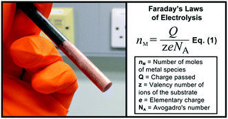 | ||
| Fig. 2 Graphite rod electrode coated with metallic copper and Faraday’s laws of electrolysis represented in eqn (1).11 | ||
Accordingly, cyclic voltammetry using a copper-coated glassy carbon working electrode (WE) (Pt wire counter electrode (CE), Ag wire QRE in 0.1 M Bu4NPF6/MeCN) shows a smooth increase in current as the potential is increased, which corresponds to the increasing rate of Cu(I) release, as shown in Fig. 3.
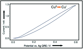 | ||
| Fig. 3 CV plot, using Cu(0)-coated glassy carbon working-electrode, Pt wire counter-electrode, and Ag wire quasi reference-electrode in 0.1 M Bu4NPF6/MeCN.11 | ||
As such, we were confident that the inclusion of a base and a terminal alkyne in a divided cell would therefore lead to the dimerized product. Disappointingly, however, when we attempted the reaction outlined in Scheme 4 with a sacrificial Cu(0) electrode, we only obtained yields of 58% for the dimerized product, along with 30% for the copper acetylide intermediate (which precipitated out of solution). Such species are known to be polymeric in nature12 and their extreme insolubility in acetonitrile was clearly impairing their reactivity in this case. Accordingly, we chose to examine the reaction in dichloromethane, a solvent in which such species are known to have higher solubility and therefore reactivity.12 Pleasingly, this relatively minor change led to the dimerized product in much improved yield (Scheme 5). The control experiments where the individual reactive components (copper, DABCO, O2) were omitted from the reaction led to a dramatic retardation of the reaction.
With this encouraging result in hand, we then proceeded to examine the reaction more closely with a view to further optimizing the conditions. At this point we decided to record the CV plots of the various components in the reaction to see what electrochemical analysis could reveal about the reaction mechanism. These tests were designed to mimic the conditions used in a ‘standard’ reaction (see Scheme 5), which meant that 0.1 M Bu4NPF6/DCM was used as the electrolyte in all cases. First we wanted to observe the production of Cu(I)/(II) from a bulk Cu(0) source, so we used a blank glassy carbon WE to record a background CV plot of the electrolyte solution up to +0.60 V (because our reactions are carried out at +0.50 V) (Fig. 4A).
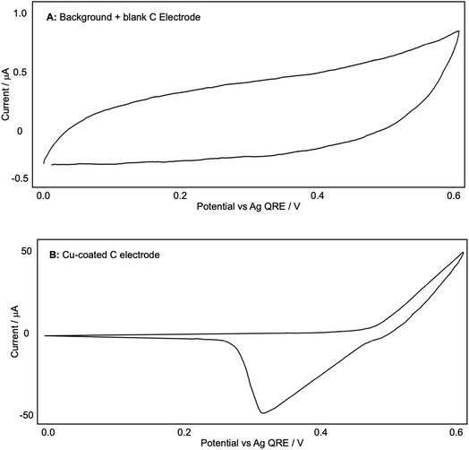 | ||
| Fig. 4 (A and B): representative CV plots of a Cu-coated C electrode recorded in 0.1 M Bu4NPF6/DCM with a Ag QRE and a Pt CE. | ||
We then coated the glassy carbon rod with a fine layer of Cu(0) by passing a reducing potential through a 0.5 M CuSO4/H2O solution (reducing the Cu(II) to Cu(0) and forming a metallic coating). This was then placed into the Bu4NPF6/DCM electrolyte solution again and another CV plot was recorded (Fig. 4B). This shows the oxidation of Cu(0) from +0.50 V onwards and the associated reduction, with a peak at +0.30 V. This appears to visualise the liberation of Cu(I) from the electrode.
We then investigated whether the presence of phenylacetylene or DABCO somehow altered this generation of Cu ions, starting with phenylacetylene. Fig. 5A and B were recorded in a fresh Bu4NPF6/DCM solution with a blank glassy carbon WE after a small amount of phenylacetylene was added. A shows the CV plot produced at up to +1.50 V (high voltage) and B shows the graph produced at up to +0.60 V (low/standard reaction voltage). An indistinct, broad oxidation peak is observed at ca. +0.9 V, with a broad reduction peak at 0.45 V; additional oxidation currents can be seen above +1.2 V. In the more limited potential range (B) although currents are a little higher than in the background scans (Fig. 4A) there is little evidence of phenylacetylene undergoing any significant oxidation up to +0.5 V, which is the potential used in our reactions. When a Cu-coated glassy carbon WE was then used to measure the CV, we obtained plot C, which shows the same potential of Cu oxidation onset and reduction peak as Fig. 4B. This suggested that phenylacetylene did not significantly affect the generation of Cu in the solution used here, or by extension in our diyne-forming reactions.
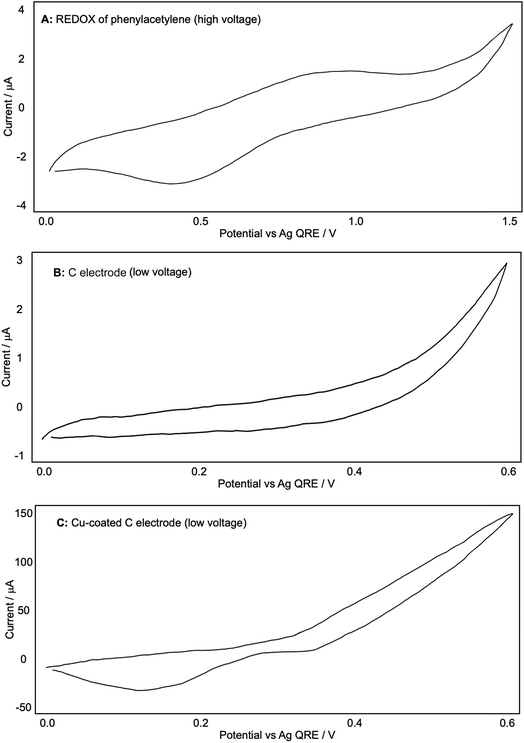 | ||
| Fig. 5 (A–C): representative CV plots of phenylacetylene recorded in 0.1 M Bu4NPF6/DCM with a Ag QRE and a Pt CE. | ||
A similar process was carried out for DABCO, as shown in Fig. 6. Using a blank glassy carbon WE and a fresh electrolyte solution, we found that the oxidation of DABCO occurred at a surprisingly high potential of around +1.10 V, and not in the +0.50 V region that is employed in our reactions (A). Other sources13 have noted the ease with which DABCO is oxidised due to the unusual stabilisation of the resulting radical cation.
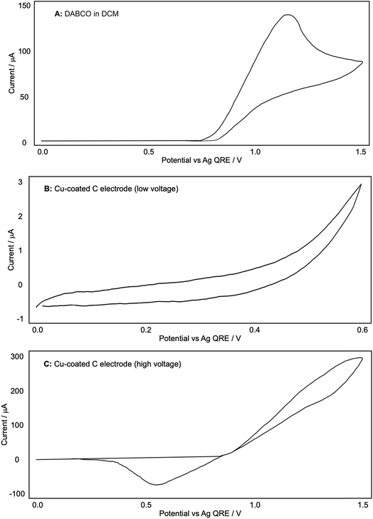 | ||
| Fig. 6 (A–C) Representative CV plots of DABCO recorded in 0.1 M Bu4NPF6/DCM with a Ag QRE and a Pt CE. | ||
When a Cu-coated WE was used, no redox currents were observed in the potential range 0 to 0.6 V in the presence of DABCO (Fig. 6B), in direct contrast to the CV plots obtained for both the Cu-coated electrode on its own (Fig. 4B) and the Cu-coated electrode with phenylacetylene (Fig. 5C). Extending the potential range enabled us to see that the onset of Cu oxidation under these conditions was +0.9 V, compared to +0.5 V observed in the absence of DABCO. The results seem to suggest that DABCO alone inhibits the dissolution of Cu and hence the formation of the reactive Cu catalyst. This is surprising given the need for DABCO in the diyne forming reactions.
Having gained some insight into the electrochemical behavior of the reactive components we then turned our attention to the effect of the solvent on our reaction. Making the seemingly trivial change of solvent from dichloromethane to chloroform resulted in an almost complete loss of reactivity with virtually no diyne being produced. This was somewhat surprising given the similarities between these two chlorinated solvents, often used interchangeably. After consulting the literature and noting that occasionally catalytic species are generated by reaction with the solvent, particularly Zhou and Yin’s observation14 that chloroform reacts with TMEDA in the presence of Cu(I), we wondered if a similar situation was occurring in this case. Accordingly, we noted that Jagner15 had discovered that DABCO, CuCl and dichloromethane readily react to generate the dinuclear Cu(I) complex shown in Scheme 6. This complex (‘Jagner’s complex’) has not to our knowledge been tested for catalytic activity in the formation of C–C bonds.
 | ||
| Scheme 6 Formation of Jagner’s complex.15 | ||
It is also distinct from the mononuclear complexes of copper(I) and DABCO described by Sekar16 where the DABCO, Cu(I) and Cl ions form linear polymeric structures with strong intermolecular hydrogen bonds (Fig. 7).
 | ||
| Fig. 7 Representation of the linear, polymeric DABCO–Cu complex described by Sekar.16 | ||
As such, it seems likely that the quaternization of DABCO by the chloromethyl moiety prevents the mononuclear polymer from forming by ‘blocking’ one of the coordinating and H-bonding sites on the DABCO molecule thereby favouring the discrete dinuclear complex. This also explains our observations in Fig. 6A where the oxidation of what we originally assumed to be DABCO occurred at a higher potential than would have been expected. Accordingly, when we performed cyclic voltammetry on the DABCO chloromethyl chloride salt prepared independently, a trace identical to that in Fig. 6A was observed. This indicates that the quaternized DABCO salt is formed very quickly (and quantitatively) in the reaction mixture and consequently is not subsequently oxidized at the potentials employed in the reaction. Interestingly, when we attempted to perform the reaction using mononuclear bases, such as NEt3, pyridine, etc. (ESI, Table S1†), only very poor conversions to the diyne were observed. This suggests that a reduction in coordinating power induced by the quaternization (DABCO pKa = 8.8, 3.0) may also be an important factor in the switch from linear mononuclear polymeric structures to discrete dinuclear copper complexes with catalytic activity.
Although the source of Cu(I) in our reactions is from the electrochemical oxidation of Cu(0), we realized that the reaction of DABCO with DCM also liberates the chloride ions necessary for the formation of CuCl in situ and thus Jagner’s complex, which we now suspected was the active catalytic species in our system. In order to confirm that this was the active species in our reaction, we used Jagner’s original procedure to independently prepare a solution of the complex. Decanting the solution away from any unreacted CuCl and then adding phenylacetylene resulted in 36% of the diyne being isolated (details in the ESI†). This suggests that Jagner’s complex is indeed the active species in our reaction. Although the yield was lower than that outlined in Scheme 5, we have attributed this to the fact that preparing the catalyst independently involves transfer losses and inefficiencies that are absent when the catalyst is prepared in situ via the electrode. Furthermore, we performed a number of experiments to establish the necessity of both DABCO and the chloride ions in the solution. The DABCO methylene chloride salt was prepared independently and added to a chloroform reaction medium (where we had previously observed a lack of reactivity) according to Scheme 7A–D.
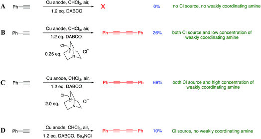 | ||
| Scheme 7 (A–D): investigation into the importance of various reaction components. In (A–C) 0.05 M Bu4NPF6/CHCl3 was used as electrolyte, whilst in D 0.05 M Bu4NCl/CHCl3 was used. | ||
Scheme 7A indicates that DABCO alone is not sufficient to promote the reaction. Full activity as observed in our original findings is only observed when all of the Cu(I), chloride ions and DABCO salt are present. Consistent with our hypothesis is that low concentrations of the added DABCO salt promoted the Glaser–Hay coupling (Scheme 7B) but less efficiently than when the concentration was increased (Scheme 7C). We also wanted to check that it was not the presence of chloride ions (rather than a monoquaternized DABCO derivative) that was promoting the reaction. Accordingly, the addition of tetrabutylammonium chloride (0.25 eq.) to the reaction mixture (Scheme 7D) in the presence of DABCO gave only a very poor conversion to the diyne, further suggesting that the DABCO salt is specifically responsible for the assembly of the active catalytic species.
We were also intrigued by the observation that the Glaser–Hay reaction could be efficiently promoted by potentials that, when compared to the original CV plots for the copper-coated electrode, were at the limits or even below the potential required for Cu(I) generation. We therefore chose to examine this phenomenon more closely. Having established the necessity for the DABCO chloromethyl salt in the reaction we also wondered if the presence of chloride ions were not only required for assembly of the catalytic complex but are also cooperatively assisting Cu(I) dissociation from the electrode surface and allowing the oxidation of Cu(0) to occur at lower potentials than the original CV plots (in the absence of chloride) would suggest. Fig. 8 shows the CV plots of (A) a Cu(0)-coated glassy carbon electrode in DCM (as described previously), (B) a blank WE with a solution of tetrabutylammonium chloride in DCM and (C) a mixture of the two.
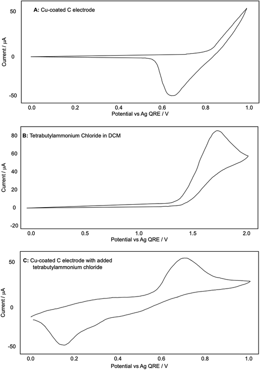 | ||
| Fig. 8 (A–C): representative CV plots examining the effect of chloride on the release of copper from a Cu-coated glassy carbon electrode recorded in 0.1 M Bu4NPF6/DCM with a Ag QRE and a Pt CE. | ||
The redox values appear shifted to slightly higher values than in Fig. 4B. We attributed this observation to our use of a quasi-reference electrode. To ensure that our measurements were comparable with previous experiments, we proceeded to reference our CV plots against the ferrocene redox couple. After performing this referencing experiment, we were confident in the comparability of the two plots with the caveat that the values were shifted up by around +0.30 V in Fig. 8A.
Fig. 8A shows clearly that the oxidation of copper from the electrode begins only at around +0.83 V and Fig. 8B shows that the oxidation of chloride to Cl2, as expected, does not occur until much higher potentials have been reached (beginning at +1.40 V and reaching a peak at +1.75 V). When chloride ions are present with a Cu-coated electrode, however, a well-defined oxidation peak is observed at +0.72 V, attributed to the oxidation of Cu(0) to Cu(I). Furthermore, this oxidation actually begins at around +0.58 V. Since oxidation is beginning at potentials lower than either individual component of the mixture, this strongly suggests that the presence of chloride, in addition to allowing the formation of a dinuclear copper complex, also cooperatively assists the release of Cu(I) from the electrode (presumably as CuCl). This allows the reactions to be performed at lower potentials than expected based on the redox behavior of any individual component of the reaction mixture (Fig. 9).
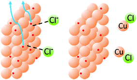 | ||
| Fig. 9 Schematic representation of the cooperative effects between chloride and copper in the release of Cu(I) from the electrode surface. | ||
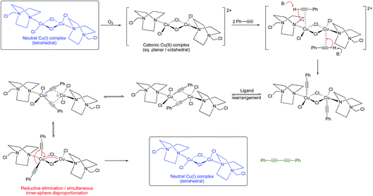
Given that Jagner’s complex is almost certainly the copper complex generated in our system, we realized that the identification of such a dinuclear copper complex lends support, at least in this case, to the Bohlmann proposal for the oxidative dimerization of alkynes. Such a dinuclear complex would not necessarily require a Cu(III) intermediate as in the Vilhelmsen model since redox-cooperative interactions between the two copper centres could occur (although we cannot rule out a Cu(III) intermediate at this stage). A possible pathway is outlined in Scheme 8.
Conclusion
In conclusion, we have described an electrochemical approach to Glaser–Hay coupling and have exploited the electrochemical technique to give valuable insight into the reaction mechanism. The identification of Jagner’s complex as a catalytic entity for Glaser–Hay coupling is the first time that this complex has been implicated in this C–C bond forming process. The results suggest that, in this case, the Bohlmann proposal for the Glaser–Hay reaction is likely. We have demonstrated how the complex might be formed and shown that the cooperativity between the chloride and the copper electrode allows facile dissociation of Cu(I) from the electrode surface at lower potentials than would be expected based on the redox behavior of either of those species. More generally, these results demonstrate that electrochemistry can be a useful tool for the investigation of organic reaction mechanisms and in synthetic chemistry.Conflicts of interest
There are no conflicts to declare.Acknowledgements
The authors thank UCL for a studentship to PWS.References
- (a) R. Bates, Organic Synthesis Using Transition Metals, Wiley-Blackwell, Sheffield, UK, 2000 Search PubMed; (b) J. F. Hartwig, Organotransition Metal Chemistry: From Bonding to Catalysis, University Science Books, US, Sausalito, 2009 Search PubMed.
- (a) C. Glaser, Ber. Dtsch. Chem. Ges., 1869, 2, 422 CrossRef; (b) C. Glaser, Justus Liebigs Ann. Chem., 1870, 154, 137 CrossRef.
- (a) A. Hay, J. Org. Chem., 1960, 25, 1275–1276 CrossRef CAS; (b) A. Hay, J. Org. Chem., 1962, 27, 3320–3321 CrossRef CAS.
- R. R. Tykwinski and A. L. K. Shi Shun, Angew. Chem., Int. Ed., 2006, 45, 1034–1057 CrossRef PubMed.
- J. Liu, J. W. Y. Lam and B. Z. Tang, Chem. Rev., 2009, 109, 5799–5867 CrossRef CAS PubMed.
- J. A. Marsden and M. M. Haley, J. Org. Chem., 2005, 70, 10213–10216 CrossRef CAS PubMed.
- G. Eglinton and A. R. Galbraith, J. Chem. Soc., 1959, 889–896 RSC.
- W. Chodkiewicz, P. Cadiot and C. R. Hebd, Seances Acad. Sci., 1955, 241, 1055–1057 CAS.
- F. Bohlmann, H. Schönowsky, E. Inhoffen and G. Grau, Chem. Ber., 1964, 97, 794–800 CrossRef CAS.
- M. H. Vilhelmsen, J. Jensen, C. G. Tortzen and M. B. Nielsen, Eur. J. Org. Chem., 2013, 701–711 CrossRef CAS.
- P. W. Seavill, K. B. Holt and J. D. Wilden, Green Chem., 2018, 20, 5474–5478 RSC.
- K. Jouvin, J. Heimburger and G. Evano, Chem. Sci., 2012, 3, 756–760 RSC.
- (a) S. F. Nelsen and P. J. Hintz, J. Am. Chem. Soc., 1972, 94, 7114–7117 CrossRef CAS; (b) R. Hoffmann, A. Imamura and W. J. Hehre, J. Am. Chem. Soc., 1968, 90, 1499–1509 CrossRef CAS.
- L. Su, J. Dong, L. Liu, M. Sun, R. Qiu, Y. Zhou and S.-F. Yin, J. Am. Chem. Soc., 2016, 138, 12348–12351 CrossRef CAS PubMed.
- B. Gustafsson, M. Håkansson and S. Jagner, Inorg. Chim. Acta, 2005, 358, 1309–1312 CrossRef.
- S. Mannam, S. K. Alamsetti and G. Sekar, Adv. Synth. Catal., 2007, 349, 2253–2258 CrossRef CAS.
Footnote |
| † Electronic supplementary information (ESI) available. See DOI: 10.1039/c9fd00031c |
| This journal is © The Royal Society of Chemistry 2019 |


