
 Open Access Article
 This Open Access Article is licensed under a Creative Commons Attribution-Non Commercial 3.0 Unported Licence
Ion-solvating membranes as a new approach towards high rate alkaline electrolyzers†
Mikkel Rykær
Kraglund
 a,
Marcelo
Carmo
b,
Günter
Schiller
c,
Syed Asif
Ansar
c,
David
Aili
a,
Erik
Christensen
a and
Jens Oluf
Jensen
*a
a,
Marcelo
Carmo
b,
Günter
Schiller
c,
Syed Asif
Ansar
c,
David
Aili
a,
Erik
Christensen
a and
Jens Oluf
Jensen
*a
aDepartment of Energy Conversion and Storage, Technical University of Denmark, Elektrovej 375, 2800 Kgs. Lyngby, Denmark. E-mail: jojen@dtu.dk
bForschungszentrum Jülich GmbH, Institute of Energy and Climate Research, IEK-3: Electrochemical Process Engineering, 52425 Jülich, Germany. E-mail: m.carmo@fz-juelich.de
cGerman Aerospace Center (DLR), Institute of Engineering Thermodynamics, 70569, Stuttgart, Germany. E-mail: guenter.schiller@dlr.de
First published on 22nd July 2019
Abstract
Energy efficient and cost efficient water electrolysis is essential for the large scale implementation of renewable energy. The two commercial low temperature electrolyzer technologies each suffer from serious drawbacks. The proton exchange membrane (PEM) electrolyzers remain expensive and depend strongly on the scarce metal iridium. The alkaline electrolyzers suffer from a large footprint due to low rate capability. Here we present an approach to make an alkaline electrolyzer perform like a PEM electrolyzer by means of an ion-solvating membrane. A long lasting effort to replace the state-of-the-art thick porous diaphragm by an anion exchange membrane has not proven successful. The ion-solvating membrane represents a third way. Demonstration cells based on KOH doped polybenzimidazole membranes and nickel based electrodes exhibited 1700 mA cm−2 at 1.8 V. This is far exceeding what has previously been achieved with membranes in alkaline environments without platinum group metal catalysts, and is comparable to state-of-the-art PEM electrolyzers.
Broader contextConversion of electrical energy into chemical energy in the form of fuels is mandatory in an energy system dominated by fluctuating renewable energy. The need for this conversion is evident in general for large-scale energy storage and more specifically for fuelling the heavy parts of the transportation sector. In fact, large-scale energy storage and powering mobility are considered some of the largest challenges in the green transition. Electrolysis of water is the first conversion step in these processes and thus the development of cost efficient and energy efficient electrolyzers with the perspective of upscaling to multi GW is crucial. The commercially available low temperature electrolyzers today are the alkaline electrolyzer and the acidic PEM electrolyzer, each with serious drawbacks that impedes large-scale implementation. The alkaline electrolyzer is only capable of low production rates per electrode area and the membrane based PEM electrolyzer, which is capable of high rate production, depends on expensive and very scarce materials for its manufacturing. A thin highly conductive polymer membrane for use in the alkaline system would combine the advantages of both systems, but so far, the attempts to develop this have been far from satisfactory. |
The generation of hydrogen via water electrolysis is currently recognized as the only viable option to store multi gigawatt-levels of electrical energy from intermittent renewable energy sources such as wind and solar, and is essential for the decarbonisation of the transportation and industrial sectors.1 Consequently, water electrolyzers will become increasingly important to the energy matrix, as they serve as a bridging technology between intermittent renewable electrical energy and chemical energy dependent sectors such as transportation and heavy industry.
Traditional electrolyzers based on alkaline electrolytes and porous diaphragms suffer from poor voltage efficiency, particularly at high current densities due to high internal resistance. Additionally, gas permeation through the porous diaphragms or even electrolyte blow-out is a concern. Such conventional systems are incapable of working with differential pressure and show slow transient response times in order to maintain balanced pressure. The overall system constraints result in a limited current density range (200–400 mA cm−2) and, consequently, the hydrogen production rate is low.2,3 On the other hand, proton exchange membrane (PEM) systems based on perfluorosulfonic acid (PFSA) membranes feature promising advantages due to their higher efficiency and wider current density window (∼500–2000 mA cm−2). However, PEM electrolyzers remain expensive due to their use of expensive PFSA membranes and precious platinum group metal (PGM) catalysts, i.e. platinum for the cathode and iridium for the anode, as well as precious metal coated titanium-based components for porous transport layers and bipolar plates.3,4 Additionally, large scale implementation will only be possible to the limit given by the availability of iridium, as it is much more scarce than platinum. There is currently no flexibility when it comes to material choices, and the channel-forming nature of the PFSA membranes ultimately shows mediocre hydrogen barrier properties under pressurized operation due to diffusion, which further complicates the balance of plant and increases system costs.4
An alkaline environment, on the other hand, allows for a cell construction completely free of PGMs and titanium based components. This has prompted substantial research on alkaline membranes for water electrolysis. A good OH−-conducting membrane could bridge the two technologies by enabling a wide range of active, non-precious metal catalysts, in combination with the low ohmic resistances and gas separation properties of a solid polymer electrolyte. The realization of alkaline membranes with sufficient conductivity and satisfactory stability could potentially induce a technological paradigm shift in which, over time, conventional alkaline systems and PEM electrolyzers get superseded.
In the quest towards improving the rate capability of alkaline electrolyzers while maintaining a reasonable degree of efficiency, significant focus has been directed towards reducing ohmic losses by developing more advanced separators and electrolyte concepts. The classical approach revolved around improving porous diaphragms,5 whereas the more recent focus has been on developing anion exchange membranes (AEMs).6 These two concepts are conceptually different and schematically illustrated in Fig. 1a and b, respectively.
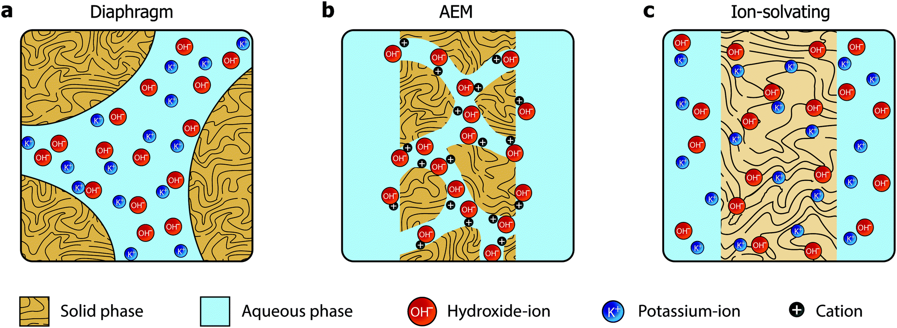 | ||
| Fig. 1 Three approaches towards hydroxide conducting separators. (a) The classical diaphragm consisting of a macroporous inactive material. The pores must form a percolating network. (b) The anion exchange membrane, where positive functional groups on pendant side chains mediate hydroxide conductivity, possibly by reorienting to form ionic channels. No aqueous electrolyte is required. (c) The ion-solvating membrane, which is imbibed with an alkaline electrolyte, commonly KOH. Significant swelling results in a homogeneous mixed phase of the polymer matrix and the electrolyte. | ||
The diaphragms (Fig. 1a) are separator materials that rely solely on the liquid phase of the electrolyte to establish percolating pathways throughout the porous structure. The diaphragm matrix is made from a stable inert polymer, and is often supported by a hydrophilic inorganic filler. Previously, asbestos cloth was used, but the current commercial state-of-the-art diaphragm is made from polysulfone-bonded ZrO2 and is often referred to by the trademark name Zirfon.7,8
AEMs (Fig. 1b), on the other hand, have been investigated for fuel cell applications since early 2000,9 but have yet to achieve success in water electrolysis due to insufficient conductivity and stability. Such membranes are based on polymers with fixed cationic side groups paired with anions that become mobile upon dissociation in the presence of water. In that sense, AEMs are alkaline analogues to PFSA membranes, and an effective and stable ionomer phase is required in the electrode to establish a vast triple phase boundary and to conduct ions inside the catalyst layer.
We present a third alternative approach, which is based on ion-solvating membranes and a supporting electrolyte. Ion-solvating membranes, conceptually sketched in Fig. 1c, are polymeric membranes, which when imbibed with KOH swell and form a homogeneous ternary electrolyte system of polymer/water/KOH. Ion-solvating membranes utilize the uptake and presence of an aqueous alkaline electrolyte to achieve ionic conductivity, and are not necessarily intrinsic hydroxide conductors, but unlike diaphragms they are dense (non-porous) and can be prepared as thin as other polymeric membranes.
A key feature when using ion-solvating membranes is the supporting electrolyte. The electrolyte not only has profound effects on the membrane itself, it also affects all aspects of the electrolyzer cell, from the catalyst layers and electrodes to the balance of plant. For alkaline water electrolysis, a hydroxide electrolyte is of particular interest and hereinafter a supporting electrolyte refers to a hydroxide-based electrolyte. Screening the literature, it is evident that AEM-based cells operated with supporting electrolytes show significantly better performance than those without. This is in particular clear from publications that evaluate cell performance with pure water or carbonate feed and with supporting hydroxide electrolyte feed.10–14 An overview of published cell performance is presented in Fig. 2, with specific details available in the ESI.† The data is grouped by the electrolyte concentration; here delimited as concentrations of KOH or NaOH above or below 0.5 M (∼0.1 S cm−1 at room temperature), and by the presence or absence of PGM catalysts. Commonly, the used electrolyte concentrations are either equal to or less than 1 wt% or at 1 M or above. On this basis, the question arises: if a supporting electrolyte is a requirement or otherwise desired for competitive cell performance, are there new avenues available to pursue instead of the conventional, functionalized pendant side-chain approach, which so far remains largely unsuccessful?
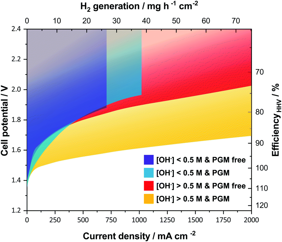 | ||
| Fig. 2 Published literature performance for alkaline electrolyzer cells using polymeric membranes. The presence of a supporting electrolyte ([OH−] > 0.5 M) improves performance and operating range. PGM catalysts still generally outperform the alternatives. The temperature range of the underlying datasets is from 22 to 80 °C. References used; without supporting electrolyte and PGM free (purple),12,39–44 without supporting electrolyte and with PGM (blue),10,11,13,14,45–47 with supporting electrolyte and PGM free (red),12,19,28,44,48–53 and with supporting electrolyte and with PGM (yellow).10,11,13,14,28,54 Further details on specific datasets are available in the ESI.† | ||
To demonstrate the perspectives of ion-solvating membranes, we have utilized KOH(aq)-doped poly(2,2′-(m-phenylene)-5,5′-bibenzimidazole) (m-PBI) as membrane. The KOH/m-PBI system was first described by Xing and Savadogo15 in 2000 for fuel cell applications, and we conducted the first demonstration for water electrolysis in 2013.16 The membranes achieve the highest specific conductivity when equilibrated in bulk electrolyte concentrations in the range of 20–25 wt% KOH17 and exhibit remarkable, though not complete stability, for up to six months in concentrated KOH.18 They do, however, in contrast to AEMs, show negligible conductivity in KOH concentrations below 5 wt%. To complement the membranes, we employed RANEY®-type nickel electrodes, which have large, electrochemically-active surface areas accessible through the supporting KOH(aq) electrolyte. For the hydrogen evolution reaction (HER), a RANEY®-type nickel-molybdenum cathode was used, whereas for the oxygen evolution, a RANEY®-type nickel anode was applied. The polarization characteristics of this cell is shown in Fig. 3, along with reference cells using state-of-the-art diaphragms and plain nickel electrodes and variations thereof. Although the cells with RANEY®-type electrodes and m-PBI membranes display an impressive rate capability of approximately 1700 mA cm−2 at 1.8 V and 2800 mA cm−2 at less than 2 V, a notable degradation in the cell potential and eventual cell failure was observed during long-term tests. While the cell voltage increase was largely due to electrode degradation, the end of life (EoL) was caused by mechanical failure of the membrane. Either in the form of electrode short circuiting, or by rapidly rising H2 in O2 levels on the anode side. Two cells using 40 μm membranes showed an EoL after approximately 120 and 147 h, while cells with 80 μm membranes displayed roughly double the lifetime of 230 and 309 h respectively. Visual inspection upon cell disassembly revealed the appearance of holes or tears in the membranes (Fig. S5, ESI†), as well as some loss of particulate matter from the electrodes evident in the membrane and in the KOH vessels. It has previously been shown that m-PBI and other polybenzimidazole derivatives experience polymer chain scission in hot and concentrated alkaline conditions,18–21 which over time lead to mechanical failure. The process is likely accelerated under polarizing conditions due to changes in the local environment of the membrane and near the electrodes.
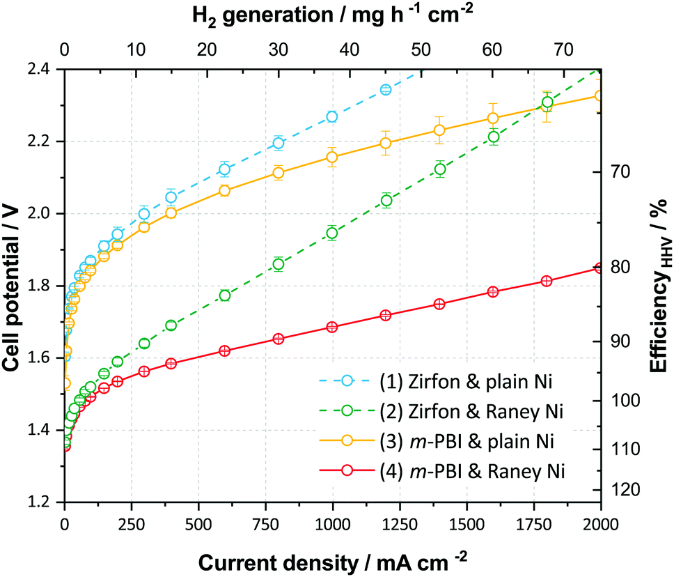 | ||
| Fig. 3 Electrochemical cell performance in 24 wt% KOH and 80 °C. Cell polarization for four different cell configurations. Error bars represent variation between two or three cells. Cells are (cathode/separator/anode): (1) Ni-foam/Zirfon™ PERL diaphragm/Ni-perforated plate; (2) RANEY®-type-NiMo/Zirfon™ PERL diaphragm/RANEY®-type-Ni; (3) Ni-foam/40 μm m-PBI membrane/Ni-perforated plate; and (4) RANEY®-type-NiMo/40 μm m-PBI membrane/RANEY®-type-Ni. | ||
In contrast to the membranes, RANEY®-type electrodes prepared by vacuum plasma spraying (VPS) have previously shown stability of more than 10![[thin space (1/6-em)]](https://www.rsc.org/images/entities/char_2009.gif) 000 h.22 However, the coatings are sensitive to the detailed preparation specifics and it is possible that the more encapsulated environment when pressed against the dense membranes result in a larger degree of pressure build-up in the pores of the coating leading to increased spallation and catalyst loss, in particular at the high current densities reached during the recording of polarization curves. Furthermore, anodic oxidation and hydroxide–oxyhydroxide formation of the nickel catalyst at the anode lead to structural expansion and possibly a pore collapse and corresponding loss of surface area, which is supported by BET data (Table S5, ESI†). Despite this and the all in all inadequate membrane stability, good performance is nonetheless achieved after a 12 h break-in as illustrated in Fig. 3, and the cells demonstrate what can be achieved using suitable electrodes and ion-solvating membranes.
000 h.22 However, the coatings are sensitive to the detailed preparation specifics and it is possible that the more encapsulated environment when pressed against the dense membranes result in a larger degree of pressure build-up in the pores of the coating leading to increased spallation and catalyst loss, in particular at the high current densities reached during the recording of polarization curves. Furthermore, anodic oxidation and hydroxide–oxyhydroxide formation of the nickel catalyst at the anode lead to structural expansion and possibly a pore collapse and corresponding loss of surface area, which is supported by BET data (Table S5, ESI†). Despite this and the all in all inadequate membrane stability, good performance is nonetheless achieved after a 12 h break-in as illustrated in Fig. 3, and the cells demonstrate what can be achieved using suitable electrodes and ion-solvating membranes.
One benefit of working with a supporting electrolyte is the option to omit the ionomer in the electrodes, since the aqueous electrolyte provides the necessary ionic pathways. This enables a wide range of electrode concepts to be employed, such as coated nickel foams, often labelled 3D electrodes or, as in this study, RANEY®-type nickel electrodes. The RANEY®-type nickel electrodes utilized in this work were not based on recent developments, but are well-proven and described in the literature.22–24 Prior to cell assembly, the electrodes were activated by alkaline leaching to remove the majority of their aluminium, resulting in a highly porous material with a very large, accessible internal surface area. Additional electrode details are available in the ESI† (Fig. S6 and Table S5). The pores are accessible to the aqueous electrolyte, but are unlikely to display the same activity if an ionomer is required, as effective pore infiltration without blocking is challenging. Hence these electrodes are best suited for conventional alkaline electrolysis or in membrane-based alkaline concepts including a supporting electrolyte. Although the cell system resembles classical alkaline electrolysis, the dense polymeric membrane can be effectively prepared much thinner than conventional diaphragms, and can correspondingly display much lower ohmic resistance. As we have demonstrated, a lower ohmic resistance enables the cells to operate at higher current densities, approaching or matching those of PEM electrolyzers. Using electrochemical impedance spectroscopy (EIS), the series resistance of cells using Zirfon was measured in the range of 0.24–0.30 Ω cm2, whereas cells with 40–80 μm thick m-PBI membranes had values of 0.04–0.08 Ω cm2 (Fig. S7, ESI†). For comparison, the reported series resistance of PEM electrolyzer cells using Nafion 115 (127 μm) as a membrane is 0.10–0.13 Ω cm2.25 This indicates a comparable conductivity, considering the difference in thickness. Naturally, the effective cell resistance is not solely a result of the membrane, but also consists of other contributions such as the ionic phase in the electrode or catalyst layer.
While a supporting electrolyte is a necessity for ion-solvating membranes, cells based on AEMs have repeatedly demonstrated increased performance when a supporting electrolyte is introduced or when the concentration is increased.10–14 Unfortunately, the large majority of AEMs developed so far are chemically unstable in an alkaline environment and can only operate satisfactorily for a few, to a few hundred, hours.6,11 The instability is primarily due to the hydroxide ions, which readily react with and degrade the anion exchange groups through nucleophilic displacement and elimination reactions.26 Another obstacle with the AEMs is their high CO2 affinity, resulting in the rapid formation of carbonates and bicarbonates and therefore a dramatic conductivity drop when exposed to ambient air.27 This makes the application of the membranes in their fully hydroxide-exchange form challenging. In this perspective, the presence of KOH(aq) is beneficial, but only so far as the stability of the anion exchange groups or polymer backbone is not critically compromised. In fact, the most impressive polarization behaviour published so far is based on a tetramethyl-imidazolium functionalized styrene AEM operated in 1 M KOH.28
A key property of membranes or diaphragms is their ability to hinder gas crossover and limit the mixing of evolved hydrogen and oxygen. This may be particularly critical when pressurized cells are operated at part load as the flushing of permeated hydrogen with the produced oxygen is reduced. Crossover is not only important from a safety point of view, but also in terms of efficiency. However, this is often a somewhat neglected aspect. General statements are frequently made, that rightfully address the porous nature of diaphragms as a problem, while proceeding to mention the dense properties of ion exchange membranes as a solution. What is rarely addressed are the differences in dominant crossover mechanisms, which were recently investigated in detail for both alkaline diaphragms and acidic Nafion membranes.29–33 In short, crossover issues through porous diaphragms primarily stem from convective transport due to differential pressure and the related movement of electrolyte with dissolved gases. For this reason, the rapid ramping of current density can be problematic, as the absolute pressure on each side of the diaphragm must be kept in close proximity. On the contrary, convective crossover is negligible in Nafion-based PEM cells, whereas crossover induced by diffusion through the hydrated microchannel structures of the membrane constitutes a significant effect, with the hydrogen diffusivity in Nafion being more than an order of magnitude larger than in KOH(aq) flooded Zirfon.31 The diffusive crossover is particularly severe under pressurized operation, as it is proportional to the concentration gradient of dissolved hydrogen, which is in turn predominantly proportional to the partial pressure, in accordance with Henry's law. Because of this, solubility in the aqueous phase is important, and both hydrogen and oxygen have a larger solubility in pure water than in aqueous KOH. There is almost an order of magnitude of difference between 0 wt% and 30 wt% aqueous KOH.31,33 This speaks positively for operating with a concentrated supporting electrolyte and lower hydrogen crossover can be expected from ion-solvating membranes in concentrated KOH(aq) than from PEMs or AEMs with hydrated ionic channels. Low crossover values in the proximity of the resolution limit of the detector were observed. For 80 μm cells operated at 100 and 1000 mA cm−2, the H2-concentrations were in the range of 0.10–0.37% and 0.00–0.03%, corresponding to a specific permeability in the vicinity of 3–12 × 10−12 mol s−1 cm−1 bar−1. This is about a factor of 5 or more lower than Nafion at 80 °C (ca. 5 × 10⁻¹¹ mol s−1 cm−1 bar−1),30,34 and similar to the Tokuyama A201 AEM at 50 °C (5.6 × 10⁻¹² mol s−1 cm−1 bar−1 at 50 °C),35 and at least indicative of good gas separation properties.
There are other differences at a cell and system level, which change when a supporting electrolyte is employed. For instance, viscosity and surface tension differ from that of pure water, which may in turn affect the bubble dislocation and gas coverage properties of the electrodes. Operating with water or an aqueous electrolyte on only one side of the membrane is perhaps less feasible and balance of plant aspects related to corrosion and catalyst dissolution and re-deposition could be more challenging.
Stability-wise, the use of a supporting electrolyte is not an insurmountable challenge when it comes to materials for electrodes, cell hardware and system auxiliary units. The main barrier in the development of this technology is the lack of a chemically-stable and mechanically-robust ion-solvating polymer membrane that can support high ion conductivity. Membranes based on polybenzimidazole indeed exhibit good performance and demonstrate the potential of the cell concept, but are intrinsically unstable in the strongly alkaline environment.18 Steric protection36 or enhancement of the electron density37 around the vulnerable sites are degradation mitigation strategies that have proven particularly successful in this context. A recently published study by Mohanthy et al.38 suggests a correlation between the presence of heteroatoms in the polymer backbone and poor alkali resistance. A rational strategy in alkaline ion-solvating polymer electrolyte membrane development is therefore to shift the focus towards stable backbone chemistries with enhanced electrolyte uptake.
Conclusions
In this paper we present a third and alternative way towards efficient alkaline electrolyte membranes for water electrolysis, by means of ion-solvating membranes. This is in contrast to conventional porous diaphragms or anion exchange membranes, which are conceptually different. Ion-solvating membranes require the presence of an aqueous hydroxide electrolyte similar to conventional systems, but are free of pendant anion exchange groups susceptible to degradation by hydroxide ions in a supporting electrolyte. A key benefit of this concept is the option to omit the ionomer in electrodes, which are commonly a weak point of AEM water electrolyzers. With 24 wt% KOH as the supporting electrolyte and thin polybenzimidazole membranes, we demonstrate polarization behaviour comparable to PEM electrolyzers, without any PGM catalysts or components. The high rate capability of 1700 mA cm−2 at 1.8 V at 80 °C demonstrates the potential of this concept, with the prospect of combining the polarization performance of PEM electrolyzers with cheap materials associated with alkaline electrolyzers. In a broader perspective, the envisioned electrolyzer system based on abundant raw materials is not only a matter of reduced cost. Equally importantly, and in contrast to the PEM electrolyzer technology, it is scalable beyond the multi GW level since it is not limited by the availability of PGMs, in particular iridium.Conflicts of interest
There are no conflicts to declare.Acknowledgements
The authors would like to acknowledge the project Boosting economic electricity storage (BEEST) funded by the EUDP programme in Denmark (no. EUDP17-1: 12542), for its financial contributing.References
- D. Stolten, Hydrogen and Fuel Cells, Wiley-VCH, Weinheim, 2010 Search PubMed.
- K. Zeng and D. Zhang, Prog. Energy Combust. Sci., 2010, 36, 307–326 CrossRef CAS.
- M. Carmo, D. L. Fritz, J. Mergel and D. Stolten, Int. J. Hydrogen Energy, 2013, 38, 4901–4934 CrossRef CAS.
- U. Babic, M. Suermann, F. N. Büchi, L. Gubler and T. J. Schmidt, J. Electrochem. Soc., 2017, 164, F387–F399 CrossRef CAS.
- V. M. Rosa, M. B. F. Santos and E. P. da Silva, Int. J. Hydrogen Energy, 1995, 20, 697–700 CrossRef CAS.
- J. R. Varcoe, P. Atanassov, D. R. Dekel, A. M. Herring, M. A. Hickner, P. a. Kohl, A. R. Kucernak, W. E. Mustain, K. Nijmeijer, K. Scott, T. Xu and L. Zhuang, Energy Environ. Sci., 2014, 7, 3135–3191 RSC.
- P. Vermeiren, W. Adriansens, J. P. Moreels and R. Leysen, Int. J. Hydrogen Energy, 1998, 23, 321–324 CrossRef CAS.
- M. Schalenbach, A. R. Zeradjanin, O. Kasian, S. Cherevko and K. J. J. Mayrhofer, Int. J. Electrochem. Sci., 2018, 13, 1173–1226 CrossRef CAS.
- D. R. Dekel, J. Power Sources, 2018, 375, 158–169 CrossRef CAS.
- X. Wu and K. Scott, J. Mater. Chem., 2011, 21, 12344 RSC.
- Y. Leng, G. Chen, A. J. Mendoza, T. B. Tighe, M. A. Hickner and C.-Y. Wang, J. Am. Chem. Soc., 2012, 134, 9054–9057 CrossRef CAS PubMed.
- C. C. Pavel, F. Cecconi, C. Emiliani, S. Santiccioli, A. Scaffidi, S. Catanorchi and M. Comotti, Angew. Chem., Int. Ed., 2014, 53, 1378–1381 CrossRef CAS PubMed.
- J. Hnát, M. Paidar, J. Schauer and K. Bouzek, Int. J. Hydrogen Energy, 2014, 39, 4779–4787 CrossRef.
- G. Gupta, K. Scott and M. Mamlouk, J. Power Sources, 2018, 375, 387–396 CrossRef CAS.
- B. Xing and O. Savadogo, Electrochem. Commun., 2000, 2, 697–702 CrossRef CAS.
- D. Aili, M. K. Hansen, R. F. Renzaho, Q. Li, E. Christensen, J. O. Jensen and N. J. Bjerrum, J. Membr. Sci., 2013, 447, 424–432 CrossRef CAS.
- M. R. Kraglund, D. Aili, K. Jankova, E. Christensen, Q. Li and J. O. Jensen, J. Electrochem. Soc., 2016, 163, F3125–F3131 CrossRef CAS.
- D. Aili, K. Jankova, Q. Li, N. J. Bjerrum and J. O. Jensen, J. Membr. Sci., 2015, 492, 422–429 CrossRef CAS.
- M. R. Kraglund, D. Aili, K. Jankova, E. Christensen, Q. Li and J. O. Jensen, J. Electrochem. Soc., 2016, 163, F3125–F3131 CrossRef CAS.
- D. Henkensmeier, H.-R. Cho, H.-J. Kim, C. Nunes Kirchner, J. Leppin, A. Dyck, J. H. Jang, E. Cho, S.-W. Nam and T.-H. Lim, Polym. Degrad. Stab., 2012, 97, 264–272 CrossRef CAS.
- O. D. Thomas, K. J. W. Y. Soo, T. J. Peckham, M. P. Kulkarni and S. Holdcroft, Polym. Chem., 2011, 2, 1641 RSC.
- G. Schiller, R. Henne, P. Mohr and V. Peinecke, Int. J. Hydrogen Energy, 1998, 23, 761–765 CrossRef CAS.
- G. Schiller and V. Borck, Int. J. Hydrogen Energy, 1992, 17, 261–273 CrossRef CAS.
- G. Schiller, R. Henne and V. Borck, J. Therm. Spray Technol., 1995, 4, 185–194 CrossRef CAS.
- H. Ito, T. Maeda, A. Nakano, A. Kato and T. Yoshida, Electrochim. Acta, 2013, 100, 242–248 CrossRef CAS.
- M. G. Marino and K. D. Kreuer, ChemSusChem, 2015, 8, 513–523 CrossRef CAS PubMed.
- M. G. Marino, J. P. Melchior, A. Wohlfarth and K. D. Kreuer, J. Membr. Sci., 2014, 464, 61–71 CrossRef CAS.
- Z. Liu, S. D. Sajjad, Y. Gao, J. Kaczur and R. I. Masel, ECS Trans., 2017, 77, 71–73 CrossRef CAS.
- M. Schalenbach, M. Carmo, D. L. Fritz, J. Mergel and D. Stolten, Int. J. Hydrogen Energy, 2013, 38, 14921–14933 CrossRef CAS.
- M. Schalenbach, T. Hoefner, P. Paciok, M. Carmo, W. Lueke and D. Stolten, J. Phys. Chem. C, 2015, 119, 25145–25155 CrossRef CAS.
- M. Schalenbach, G. Tjarks, M. Carmo, W. Lueke, M. Mueller and D. Stolten, J. Electrochem. Soc., 2016, 163, F3197–F3208 CrossRef CAS.
- M. Schalenbach, W. Lueke and D. Stolten, J. Electrochem. Soc., 2016, 163, F1480–F1488 CrossRef CAS.
- P. Trinke, P. Haug, J. Brauns, B. Bensmann, R. Hanke-Rauschenbach and T. Turek, J. Electrochem. Soc., 2018, 165, F502–F513 CrossRef CAS.
- H. Ito, T. Maeda, A. Nakano and H. Takenaka, Int. J. Hydrogen Energy, 2011, 36, 10527–10540 CrossRef CAS.
- H. Ito, N. Kawaguchi, S. Someya, T. Munakata, N. Miyazaki, M. Ishida and A. Nakano, Int. J. Hydrogen Energy, 2018, 43, 17030–17039 CrossRef CAS.
- O. D. Thomas, K. J. W. Y. Soo, T. J. Peckham, M. P. Kulkarni and S. Holdcroft, J. Am. Chem. Soc., 2012, 134, 10753–10756 CrossRef CAS PubMed.
- D. Henkensmeier, H. Cho, M. Brela, A. Michalak, A. Dyck, W. Germer, N. M. H. Duong, J. H. Jang, H.-J. Kim, N.-S. Woo and T.-H. Lim, Int. J. Hydrogen Energy, 2014, 39, 2842–2853 CrossRef CAS.
- A. D. Mohanty, S. E. Tignor, J. A. Krause, Y.-K. Choe and C. Bae, Macromolecules, 2016, 49, 3361–3372 CrossRef CAS.
- L. Xiao, S. Zhang, J. Pan, C. Yang, M. He, L. Zhuang and J. Lu, Energy Environ. Sci., 2012, 5, 7869 RSC.
- Y.-C. Cao, X. Wu and K. Scott, Int. J. Hydrogen Energy, 2012, 37, 9524–9528 CrossRef CAS.
- X. Wu and K. Scott, J. Power Sources, 2012, 214, 124–129 CrossRef CAS.
- M. Faraj, M. Boccia, H. Miller, F. Martini, S. Borsacchi, M. Geppi and A. Pucci, Int. J. Hydrogen Energy, 2012, 37, 14992–15002 CrossRef CAS.
- X. Wu and K. Scott, Int. J. Hydrogen Energy, 2013, 38, 3123–3129 CrossRef CAS.
- J. Hnát, M. Plevová, J. Žitka, M. Paidar and K. Bouzek, Electrochim. Acta, 2017, 248, 547–555 CrossRef.
- X. Wu and K. Scott, J. Power Sources, 2012, 206, 14–19 CrossRef CAS.
- J. Parrondo, C. G. Arges, M. Niedzwiecki, E. B. Anderson, K. E. Ayers and V. Ramani, RSC Adv., 2014, 4, 9875 RSC.
- E. J. Park, C. B. Capuano, K. E. Ayers and C. Bae, J. Power Sources, 2018, 375, 367–372 CrossRef CAS.
- S. H. Ahn, B.-S. Lee, I. Choi, S. J. Yoo, H.-J. Kim, E. Cho, D. Henkensmeier, S. W. Nam, S.-K. Kim and J. H. Jang, Appl. Catal., B, 2014, 154–155, 197–205 CrossRef CAS.
- J. Schauer, J. Žitka, Z. Pientka, J. Křivčík, J. Hnát and K. Bouzek, J. Appl. Polym. Sci., 2015, 132, 42581 CrossRef.
- L. A. Diaz, J. Hnát, N. Heredia, M. M. Bruno, F. A. Viva, M. Paidar, H. R. Corti, K. Bouzek and G. C. Abuin, J. Power Sources, 2016, 312, 128–136 CrossRef CAS.
- D. Aili, A. G. Wright, M. R. Kraglund, K. Jankova, S. Holdcroft and J. O. Jensen, J. Mater. Chem. A, 2017, 5, 5055–5066 RSC.
- D. Chanda, J. Hnát, T. Bystron, M. Paidar and K. Bouzek, J. Power Sources, 2017, 347, 247–258 CrossRef CAS.
- L. A. Diaz, R. E. Coppola, G. C. Abuin, R. Escudero-Cid, D. Herranz and P. Ocón, J. Membr. Sci., 2017, 535, 45–55 CrossRef CAS.
- X. Li, F. C. Walsh and D. Pletcher, Phys. Chem. Chem. Phys., 2011, 13, 1162–1167 RSC.
Footnote |
| † Electronic supplementary information (ESI) available: Experimental details and details on reviewed literature. See DOI: 10.1039/c9ee00832b |
| This journal is © The Royal Society of Chemistry 2019 |