
 Open Access Article
 This Open Access Article is licensed under a Creative Commons Attribution-Non Commercial 3.0 Unported Licence
A versatile and membrane-less electrochemical reactor for the electrolysis of water and brine†
S. Mohammad
H. Hashemi
 *ab,
Petr
Karnakov
b,
Pooria
Hadikhani
a,
Enrico
Chinello
c,
Sergey
Litvinov
b,
Christophe
Moser
c,
Petros
Koumoutsakos
b and
Demetri
Psaltis
a
*ab,
Petr
Karnakov
b,
Pooria
Hadikhani
a,
Enrico
Chinello
c,
Sergey
Litvinov
b,
Christophe
Moser
c,
Petros
Koumoutsakos
b and
Demetri
Psaltis
a
aLaboratory of Optics, École Polytechnique Fédérale de Lausanne (EPFL), Lausanne, Switzerland. E-mail: mohammad.hashemi@epfl.ch
bComputational Science & Engineering Laboratory, ETH Zurich, Zurich, Switzerland
cLaboratory of Applied Photonic Devices, École Polytechnique Fédérale de Lausanne (EPFL), Lausanne, Switzerland
First published on 5th March 2019
Abstract
Renewables challenge the management of energy supply and demand due to their intermittency. A promising solution is the direct conversion of the excess electrical energy into valuable chemicals in electrochemical reactors that are inexpensive, scalable, and compatible with irregular availability of electrical power. Membrane-less electrolyzers, deployed on a microfluidic platform, were recently shown to hold great promise for efficient electrolysis and cost-effective operation. The elimination of the membrane increases the reactor lifetime, reduces fabrication costs, and enables the deployment of liquid electrolytes with ionic conductivities that surpass those allowed by solid membranes. Here, we demonstrate a membrane-less architecture that enables unprecedented throughput by 3D printing a device that combines components such as the flow plates and the fluidic ports in a monolithic part, while at the same time, providing tight tolerances and smooth surfaces for precise flow conditioning. We show that inertial fluidic forces are effective even in millifluidic regimes and, therefore, are utilized to control the two-phase flows inside the device and prevent cross-contamination of the products. Simulations provide insight on governing fluid dynamics of coalescing bubbles and their rapid jumps away from the electrodes and help identify three key mechanisms for their fast and intriguing return towards the electrodes. Experiments and simulations are used to demonstrate the efficiency of the inertial separation mechanism in millichannels and at higher flow rates than in microchannels. We analyze the performance of the present device for two reactions: water splitting and the chlor-alkali process, and find product purities of more than 99% and Faradaic efficiencies of more than 90%. The present membrane-less reactor – containing more efficient catalysts – provides close to 40 times higher throughput than its microfluidic counterpart and paves the way for realization of cost-effective and scalable electrochemical stacks that meet the performance and price targets of the renewable energy sector.
Broader contextHydrogen – the simplest and lightest element – is the most abundant matter in the Universe, and yet its concentration in Earth's crust is relatively low. Therefore, before being widely adopted as a fuel, it is necessary to produce H2 in a sustainable and economical way. Electrolysis can provide enough hydrogen by splitting water molecules using electrical power. Thanks to the advancements in renewable energy technologies, electrical power is becoming inexpensively available, but with significant supply fluctuations. There is a two-fold opportunity for clean hydrogen generation in this regard: cost of electricity is no longer a burden and there is a critical need to store the excess amount of energy at the peak production times. To fully harness its potential and move towards a green energy landscape based on hydrogen, a critical step is to make cost-effective and efficient electrolyzers. Ion-conductive membranes or separators are costly and delicate components used in current electrolyzers to keep apart the reaction products. This study shows the scalability of the recently introduced membrane-less technology not only for water electrolysis, but also for electrosynthesis of chlorine and caustic soda. This effort is a step towards the implementation of a viable carbon neutral energy infrastructure. |
Introduction
In recent years, electrochemical reactions are becoming increasingly important for energy storage and conversion devices. Concerns over the environmental impact and sustainability of fossil fuels have promoted the rapid growth of renewable forms of energy and, in turn have introduced new challenges for the energy sector.1 The intermittent production by renewable sources needs to be addressed in order to ensure their efficient exploitation and increase their penetration in the world's energy portfolio. An appealing solution is the conversion and storage of renewable electricity in a clean and carbon-free chemical fuel such as hydrogen.2 Sustainability and environmental concerns dictate in turn that hydrogen should come from a clean process such as water electrolysis, powered by renewable electricity. This makes revisiting the well-established electrolysis technologies a necessity since the traditional reactors are not able to supply hydrogen at competitive prices and relevant scales. Therefore, innovative solutions are essential in facilitating the deployment of hydrogen based storage systems.3 It is worth noting that any advances in this field can potentially benefit all other electrochemical processes as well and eventually encourage further adoption of renewables by them.3 The chlor-alkali process is fundamental for the world's chemical industry with its two main products, i.e. caustic soda and chlorine, used as commodities in manufacturing of more than 50 percent of specialty chemicals.4 Aluminum metal is another major inorganic product of electrochemical reactors. In addition to inorganic materials, electrochemistry is involved in the production of a wide range of organic chemicals such as azobenzene, adiponitrile, and perfluorinated hydrocarbons.5There are three main components in the electrochemical cells architecture: an anode, a cathode, and a membrane or separator. The membrane allows the passage of ions through its structure and at the same time, prevents the mixing of reduction and oxidation products or reactants. Consequently, the membrane is a critical component of electrochemical cells in terms of lifetime, price, and manufacturing due to limitations it imposes on the materials of the anode and the cathode. The membrane cell is commonly used today in chlor-alkali process and is gradually replacing the diaphragm and mercury cells due to their environmental concerns,6 cost and sensitivity to trace amounts of ions such as Mg2+ and Ca2+ in the feed brine.7 However, these ions limit the lifetime of the membrane as well and cause a gradual loss in the efficiency of the cells. Exposure to the high pressure gases coupled with fluctuating renewable sources, induce fatigue that can exacerbate the degradation rate.8 Similar problems apply to the membranes in water electrolyzers. In terms of price, membrane electrode assemblies comprise 24% of the cost of a proton exchange membrane (PEM) stack.9 These factors have been driving the ongoing quest for newer and more reliable membranes/separators.10–13
An intriguing remedy to the above stated drawbacks is the complete removal of the membranes from the cells and its replacement with a highly conductive liquid electrolyte. This concept has been widely studied in electrochemical power sources such as flow batteries14,15 and fuel cells.16,17 Such membrane-less or membrane-free devices rely on the single phase and laminar flows of the oxidant and the fuel in a high Péclet regime, where the mixing of these two streams is minimal.18,19 We note a number of alternative membrane-less concepts including flow through porous electrodes,20,21 gas diffusion electrodes,22,23 and redox mediators.8,24
Despite the compact form factor and design simplicity of the membrane-less configurations, their adoption in electrochemical reactors is limited. One of the main reasons is the fact that earlier membrane-less designs function with single phase flows, which limit their utility. Although multiphase flows often appear in the electrochemical reactors,25 the complexity of controlling gaseous bubbles26 in liquid flows has hindered the successful demonstration of a two-phase flow membrane-less fuel cell until recently.27 For the same reason, it was only in 2015 that the elimination of membranes from the water electrolyzers was demonstrated, when a microfluidic proof-of-concept electrolyzer – motivated by inertial microfluidics28,29 – was reported to separate the product gases by taking advantage of inertial fluidic forces acting on the bubbles.30 This effort together with subsequent studies31–35 has triggered further investigations of membrane-less concepts for electrolyzers.36 This is a promising sign for the potential of this principle in shifting the paradigm of electrolysis for renewable energy conversion and storage.
In this work, we exploit the bubble dynamics26 and present an appropriate scale-up strategy37 to implement a functional and versatile membrane-less cell constructed with additive manufacturing38–41 (see Fig. 1). Like many other fields, the electrochemistry community has benefited significantly from 3D printing42 for electrochemical sensing,43 fabrication of complex electrodes,44–46 and reactor components32,47 among others. The tight tolerances and reduction of the number of the parts and steps in the manufacturing process of a typical electrochemical reactor are the biggest advantages offered by additive manufacturing for fabrication of electrochemical reactors. The possibility to tune the surface roughness of parts by selecting the appropriate 3D printing technology is another advantage where rough surfaces such as electrodes – or smooth surfaces – such as flow channels – are highly desirable. Besides all these advantages, there are certain concerns over the reliability of printed parts in terms of their mechanical and chemical properties. There are many research efforts trying to address these issues and some recent works report parts with impressive properties.48
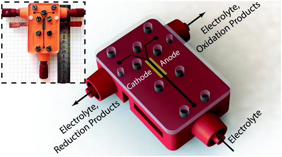 | ||
| Fig. 1 Schematic illustration of the electrolysis cell: the main body (in red) is 3D printed with stereolithography technology. The electrodes (in yellow) are pressed into the devised slots and the assembly is covered by a transparent PMMA plate. A flexible sealing film is sandwiched in between this plate and the 3D printed part to prevent leaking. The inset shows the final assembled device with attached fluidic connectors. | ||
In a scaled-up membrane-less cell, the interaction of bubbles and their coalescence dynamics can lead to more violent flow patterns49 that impact the performance of the reactor. This is even more critical if we consider that almost all studies in inertial microfluidics are done in microchannels, as this field's name suggests, and at Reynolds numbers well below 100. Unlike these works,28,29 we are investigating flow regimes with Re as high as 312. Extension of this effect to higher Re flows in larger channels and for deformable and interacting entities such as gas bubbles is of potential interest to the fields other than biotechnology as we report here. An important observation under these conditions is the abrupt changes in the equilibrium positions of the bubbles after coalescence and their subsequent return towards the electrodes. Such a behavior has been reported before in the cells with static electrolytes,50,51 but to our knowledge, this is the first report on this phenomenon in a flow-based cell. Using numerical simulations, we report mechanisms that induce the return of the bubbles and provide evidence for the strength and importance of each.
We remark that the 3D printed electrochemical reactor of the present study shows a 37-fold throughput enhancement over the first microfabricated prototype30 for water electrolysis. Furthermore, it is successfully tested for the most important industrial electrochemical reaction, i.e. the chlor-alkali reaction. To the best of our knowledge, implementing a membrane-less flow cell for this reaction is not investigated elsewhere. We find that the performance of this device compares well with the commercial water electrolyzers and brine electrolysis cells. This study demonstrates for the first time that the inertial separation of the bubbles can be realized beyond microgeometries and at higher flow rates, establishing it as a viable technology for electrolysis in the energy sector.
Methods
Reactor architecture
The electrochemical cell of this study contains three main parts. Its schematic architecture is provided in Fig. 1 with the picture of the real device in the inset. The main body which is 3D printed using stereolithography technology (Envisiontec Perfactory P4 Mini XL) contains the fluidic channels, female Luer Lock fluidic connectors, devised grooves for the electrodes integration, access holes for electrical connections, and holes for assembly screws. The second part is a pair of laser cut electrodes with the size of 4 mm by 10 mm. These electrodes were purchased in large sheets from De Nora S.p.A. (Milan, Italy) and were used as both anode and cathode. The active surface is coated with the traditional DSA™ blend, which is a 20 μm thick layer containing IrO2, RuO2, and TiO2. These mixed metal oxides are deposited on the surface of a 1 mm thick titanium substrate. The SEM micrographs of electrode's surface are provided in Fig. S1 (ESI†). Each of the electrodes is inserted with a tight tolerance into the devised grooves of the 3D printed chassis by means of a mechanical press. After integration, a part of their active area with the size of 1 mm by 10 mm forms part of the electrolyzer's channel walls and is exposed to the electrolyte flow. The main channel in the electrolyzer has a cross section of 1 mm by 1 mm, is 26 mm long, and leads into a Y-shaped section whose each branch is connected to a separate outlet. Each outlet is dedicated to collect one of the products plus the liquid electrolyte. The active area of the main channel – i.e. the area covered by the electrodes – starts 10 mm before the bifurcation and ends right at its beginning. The rest of the electrodes’ body is buried into the grooves and at the backside they are glued to two copper bars using a conductive epoxy (Conductive Epoxy CW2400 from Circuit Works). The copper bars are used to connect the potentiostat probes for electrochemical characterization and measurements. The cell is closed at the top by a 3 mm thick sheet of PMMA that contains the exact same screw holes of the main body. In between the PMMA cover and the 3D printed part, a 250 μm thick flexible and transparent sealing tape (EATSTAPE 25/0.2 from Sumitube) is employed in order to prevent the leakage. The two parts are then tightened against each other using a series of M3 and M2 screws and nuts. Male Luer Lock connectors are connected to the inlets and outlets of the final assembly to fix the PTFE tubes that introduce the electrolyte in and take products out of the device.Experimental setup
In order to characterize the performance of this electrochemical reactor, we have run a series of electrochemical tests with a Biologic SP-200 potentiostat for two different reactions: the water splitting and the brine electrolysis. In all experiments, the reactor was fixed with tapes on a flat surface of a bench or a table. The channel direction was almost perpendicular to the gravity and we did not observe any effects of the buoyancy on the results in this orientation.The liquid electrolyte is sent to the reactor from a reservoir whose overhead space is connected to a high pressure nitrogen gas line and its pressure is set by a pressure controller (ELVEFLOW OB1 MK3) connected to a mass flow meter (Bronkhorst MINI CORI-FLOW M13) to deliver the preset flow rate. For analysis of products in the water splitting reaction, each reactor outlet is connected to inverted glassware with septum caps to collect the gases for injection into the Gas Chromatograph (GC). For the chlor-alkali reaction, the liquid coming out of each outlet is collected in separate containers. These samples are then analyzed with a colorimetric comparator and a pH meter. The high solubility of Cl2 in water – 7.25 g in 1 kg water at 20 °C and partial pressure of 0.965 bar52 – means that in our measurements, most of chlorine dissolves in the anolyte and, therefore, colorimetric analysis is appropriate.
The transparent top cover of the reactor allows for visual inspection of the two-phase flow kinetics under a microscope with a Photron Mini UX100 fast camera. This allows for a qualitative investigation of the bubble dynamics before moving to a more sophisticated analytical method such as GC (Fig. 3). We used this visual technic only for the water splitting reaction due to the safety concerns over chlorine in the other reaction and recorded videos at 4000 fps for a range of flow rates and current densities.
A PerkinElmer AutoSystem XL GC machine equipped with a thermal conductivity detector has been used to characterize the purity of hydrogen for the first reaction and a colorimetric comparison technic combined with pH measurements is employed for the second reaction. We have collected the gaseous products coming out of each outlet under two inverted glass cylinders for a fixed amount of total current passing through the device, in order to quantify the gas crossover values. The gas samples were then injected into the GC using sample lock gastight syringes. This procedure was repeated three times for eight sets of current densities and flow rates using 0.5 M H2SO4 as the electrolyte. The Faradaic efficiencies in the brine electrolysis are measured using a Lovibond® CHECKIT colorimetric comparator test-kit that can quantify the total chlorine content in the range of 10 to 300 mg of chlorine per liter of solution with a resolution of 10 mg l−1. The test has been run for four flow rates at two different current densities. Each experiment is repeated three times.
We note that the same reactor has been used for tens of hours of measurements and analysis while no noticeable drop was observed in its electrochemical characteristics. For all water splitting experiments in, we recirculated one liter of 1 M or 0.5 M sulfuric acid. Before each cycle, the electrolyte was filtered using a glass frit filter to remove potential particulate contaminations.
Computational methods
We complement the experiments with advanced flow simulations to study the bubble dynamics. The computational model is based on two-component incompressible flows described by the Navier–Stokes equations and an advection equation of the gas volume fraction: | (1) |
 | (2) |
 | (3) |
The equations are discretized using a finite volume scheme employing the SIMPLE method53,54 for pressure coupling and the Volume-of-Fluid (VOF) method with piecewise linear interface reconstruction55 for the advection equation. The surface tension force at the interface S is calculated as fσ = σκ∇α + ∇SσδS following the continuum surface force approach56 with the interface curvature κ estimated from the reconstructed interface and the surface tension coefficient σ, defined either as a constant value or with a prescribed spatial profile.
The model is implemented using the Cubism framework for high performance computing57 and has been validated with various experimental results including inertial focusing of bubbles in a microchannel26 and coalescence of bubbles58 as shown in Fig. S2 and S3 (ESI†).
Results and discussion
Transport of species
Insight on understanding the transport mechanisms of species in the flow-based reactor and their relative importance is crucial for selecting the right set of parameters that lead to its optimized performance. In electrochemical reactions, the net macroscale transport of a species can be described in terms of diffusion, migration, and convection processes: | (4) |
 | (5) |
 | (6) |
In eqn (5), two dimensionless numbers appear: the Péclet number (Pe) which signifies the relative magnitude of convection to diffusion and what we call the CM number that compares the convection to migration strength:
 | (7) |
In the above definitions, L is the characteristic length (interelectrode distance) that is used to non-dimensionalize the spatial dimensions, i.e. x, y, and z in Cartesian coordinates.
The dimensionless numbers of eqn (7) together with the Reynolds number (ESI†) that indicates the relative magnitude of inertial to viscous forces are very useful in selecting the right set of working parameters to obtain highly pure products and to suppress undesirable reactions in the cell.
Fig. 2 illustrates the two reactions of interest in this study within the membrane-less architecture. In water splitting (Fig. 2a), oxygen bubbles evolve at the anode and hydrogen bubbles at the cathode. These bubbles need to be extracted through their dedicated outlets – i.e. each branch of the Y-shaped channel – while preventing the O2 and H2 bubbles to merge. This can be achieved by increasing the inertial forces to keep the two gases apart. However, a very small amount of the product gases may still dissolve in the liquid electrolyte and diffuse across the width of the channel. This process needs to be minimized since it can cause parasitic side reactions and increase gas impurities on the side opposite to their initiation. This can be controlled by having high Pe flows so that a major portion of the dissolved gases is transported out through convection. On the other hand, high flow rates require more pumping power. We have shown previously that the pumping power is negligible compared to the energy content of the generated hydrogen.30
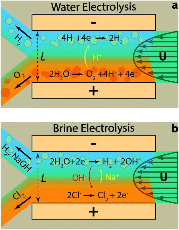 | ||
| Fig. 2 The membrane-less reactor of this study is tested for two electrochemical reactions: (a) water electrolysis and (b) brine electrolysis. The flow rate in both cases should be fast enough to minimize the crossover due to the diffusion of dissolved gases and provide large inertial forces to keep the gas bubbles of each side away from the channel's centreline. In the brine electrolysis, the convective transport of hydroxide ions should also dominate its diffusion towards the anode, which can initiate oxygen evolution as a competing reaction for chlorine evolution. | ||
In acidic electrolytes, protons are generated in the oxidation half-reaction and consumed in the reduction half-reaction. Therefore, their transport through migration and diffusion from the anode towards the cathode is desirable. The same principles hold for the gaseous and dissolved chlorine and hydrogen evolved in the brine electrolysis (Fig. 2b). However, at the same time, the transport of generated hydroxide ions through migration and diffusion from the cathode to the anode is not desirable. Therefore, the electrolyte flow needs to have a high CM number in addition to large Pe and Re numbers. These dimensionless numbers can be calculated using eqn (4) and the definition of Re number (ESI†) based on the values listed in Table 1 and Tables S1–S3 (ESI†) for different species. It is clear from Table 1 that the most critical transport phenomenon for the proper operation of the cell is the migration of hydroxide ions since its CM number is two orders of magnitude smaller than the Pe number for different species. Since a CM of 129 is large enough to minimize the effect of OH− migration to the other side, we choose 8 cm s−1 – used in calculations of Table 1 – as the minimum average velocity in the cell during our experiments. Such a velocity leads to Re number of at least 67 for our electrolytes (Tables S1–S3, ESI†). Effectiveness of this Re for inertial separation of bubbles is tested in the experiments. We note that by high Re in this study, we mean a Re value much larger than 1 but within the Re limit of laminar flows.
![[thin space (1/6-em)]](https://www.rsc.org/images/entities/char_2009.gif)
Water splitting
Visual investigation of the bubble dynamics provides a qualitative tool to probe the impact of current density and flow rate on the bubbles trajectory. Lateral migration of bubbles in the crossflow direction is observed in microfluidics when the Reynolds number is much larger than one.26,62 It has been shown that the equilibrium position of bubbles is different than that of rigid particles in a channel with similar geometry.26 In this work we selected a square channel as the bubbles tend to equilibrate at its four corners and, therefore, provide the desired products separation.Fig. 3a–c present snapshots of the bubbles in the upstream, midstream, and downstream regions of the electrolysis cell, respectively. Each image in these figures corresponds to a specific flow rate (from 300 to 1200 ml h−1) and current density (300 and 450 mA cm−2). In addition, Movies S1 to S3 (ESI†) show the bubble dynamics in the three above-mentioned regions of the cell for Re of 312 and current density of 450 mA cm−2. These videos – recorded at 4000 fps – play back at 30 fps.
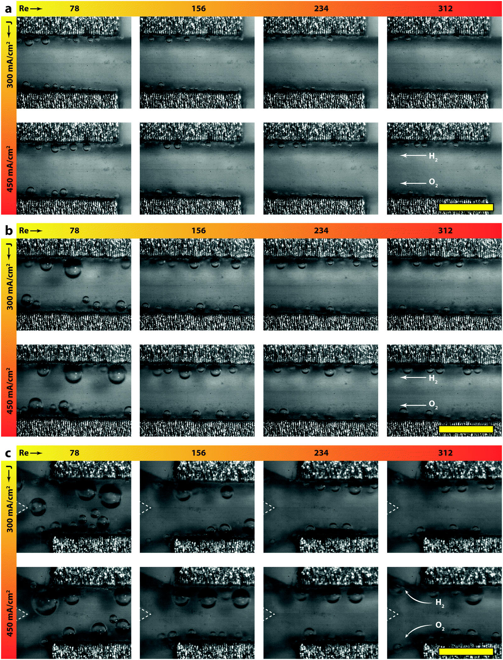 | ||
| Fig. 3 Snapshots of the upstream (a), midstream (b), and downstream (c) regions of the electrolyzer: in general, the volume fraction and average size of bubbles increase with decreasing flow rate or increasing the current density. At low flow rates, some bubbles depart from the walls and move towards the center since the inertial forces are not strong enough. This phenomenon increases the crossover rate at these conditions as quantified by the GC results. The separating wedge is highlighted with a dashed triangle for better clarity in the downstream figures. The yellow scale bars at the corners are 1 mm in size. | ||
Fig. 4 shows the polarization curves for four different flow rates of 1 M (Fig. 4a) and 0.5 M (Fig. 4b) sulfuric acid as electrolyte. Increasing the flow rate from 300 ml h−1 (Re = 73) to 1200 ml h−1 (Re = 292) leads to an increase in the current density from 475 mA cm−2 to 519 mA cm−2 at 2.5 V, when working with 1 M acid. Repeating the same measurement (Re = 78 to 312) for 0.5 M acid, enhances the current density from 399 mA cm−2 to 432 mA cm−2. The increased throughput with flow rate is intuitive since a higher flow rate exerts larger drag forces on the nucleated bubbles and, therefore, decreases their detachment size.63 This implies that the percentage of catalyst surface area covered by bubbles in course of reaction is reduced, resulting in a larger number of reaction active sites. Furthermore, the volume fraction of gas is lower in a fast flowing liquid electrolyte. This contributes to the reduction of ohmic losses in between the electrodes.64 Interestingly, fast flowing electrolytes – as in the membrane-less architecture – are appealing for generation of solar fuels. The inherent fluctuations of the renewable electricity require fast dynamic response from the electrolyzer in order to prevent large overpotentials and products crossover. This is why optimizing the electrolyte flow rate in alkaline cells is crucial before deploying them in the power-to-gas industry.65 Besides the advantages of flow-based schemes for efficient transport of bubbles, they also facilitate the transport of ions in reactors that employ electrolytes with near neutral pH.66
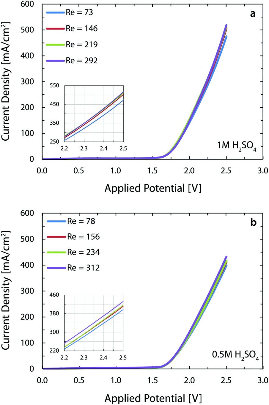 | ||
| Fig. 4 Polarization curves of the water splitting reaction with 1 M (a) and 0.5 M (b) sulfuric acid electrolytes for different flow rates. In both cases, going from the lowest to the highest Re increases the current density by around 10% thanks to the lower volume fraction of the gases in the cell and smaller sizes of detached bubbles. The performance of the cell is similar to the state-of-the-art alkaline electrolyzers but with more dilute and safer electrolytes and at room temperature. The inset provides a detailed view of the data above 2.2 V. | ||
We note that the present current densities are approximately 250% higher than the respective microfluidic membrane-less electrolyzer30 employing the same electrolyte. The reasons behind this significant improvement are: (1) the parallel plate arrangement of the electrodes in the current device provides more uniform current distribution as opposed to the in-plane arrangement of the previous study, and (2) use of better catalysts with significantly lower overpotentials, especially for the oxygen evolution reaction (OER). This second point is clearly noticeable when we compare the onset potential of 2.10 V in the earlier study versus the present 1.64 V, assuming a current density of 10 mA cm−2 for both cases. These two positive factors outweigh the five-fold increase in the interelectrode distance of the current 3D printed cell and combined with the benefit of using much larger electrodes, lead to a 37-fold enhancement in the throughput of the current reactor versus the microfluidic implementation.
The performance of the reactor in this paper is comparable to the state-of-the-art alkaline electrolyzers which operate at the voltage and current density ranges of 1.8–2.4 V and 200–400 mA cm−2 and reach a temperature of 60 to 80 °C with a strong KOH solution (∼30 wt%) as the electrolyte.67 The current reactor operates at more than 400 mA cm−2 at a voltage of 2.4 V with a less conductive, but safer electrolyte and at room temperature. These substantial benefits however come at the price of using more expensive electrodes in this reactor versus Ni-based electrodes in the alkaline electrolyzers.
The Potentio Electrochemical Impedance Spectroscopy (PEIS) measurements are done using both electrolytes to characterize the solution resistance in the membrane-less cell. Fig. 5a indicates an average resistance of 6.7 Ω for 1 M sulfuric acid and Fig. 5b shows the value to be 10 Ω for the 0.5 M acid. The ionic conductivity of 1 M and 0.5 M sulfuric acid is 0.38 and 0.20 S cm−1, respectively.68 Using these values and the cell dimensions in the Ohm's law, the ohmic drops for these two concentrations are expected to be 2.6 and 5 Ω. The larger values from PEIS measurements are mostly due to the added effect of the ohmic contacts through conductive epoxy and copper bars. At 400 mA cm−2, this difference translates into roughly 200 mV of overpotential. Soldering or brazing the electrodes to the copper bars can significantly reduce this loss and further improve the performance.
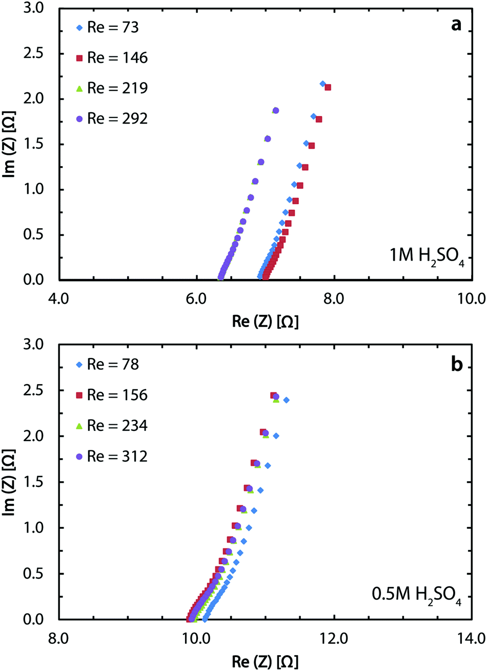 | ||
| Fig. 5 PEIS measurements for the water splitting reaction with 1 M (a) and 0.5 M (b) sulfuric acid electrolytes at different flow rates. The obtained ohmic losses are larger than the calculated values from Ohm's law since the losses at the contacts between the electrodes and the power source are measured here in addition to the solution resistance. Better ohmic contacts can provide up to 200 mV reduction in the cell voltage when working at around 400 mA cm−2. | ||
A GC is employed to obtain the average values of the hydrogen crossover and corresponding measurement errors as presented in Fig. 6. The green zone shows the region where the crossover values are below 4% and, therefore, the gas mixtures are non-explosive. The results indicate that for the lowest tested flow rate, the reactor does not generate safe and pure gas streams which is consistent with Fig. 3 and Movies S1 to S3 (ESI†). By increasing the flow rate, the crossover decreases regardless of the tested current density values since the flow-based separation mechanism described before comes into effect.
 | ||
| Fig. 6 GC results for a set of flow rates and current densities. The green zone shows the safe region where the gas crossover (below 4%) does not lead to an explosive mixture. By increasing the flow rate, the separation of gas bubbles based on the inertial fluidic forces come into effect which leads to almost pure streams of the gases at the outlets. | ||
Bubble coalescence dynamics
In our first microfluidic electrolyzer,30 we were not able to observe the dynamics of bubble coalescence due to the lack of a transparent window in the chip. In a follow-up report, we focused on understanding the inertial migration of the monodisperse and non-interacting bubbles.26 However, in a scaled-up reactor such as the one in this study, the higher convection flow conditions result in an increased number of coalescence events that may affect separation of the products. The current reactor provides the possibility to observe and capture the coalescence of bubbles and its effect on the trajectory of the resulting large bubbles.An interesting observation in many coalescence events is the jump-off of the newly formed bubble and its subsequent return towards the electrode. This intriguing phenomenon has been observed before in cells with static electrolytes,50,51,69 but to the best of our knowledge, this is the first report of this phenomenon under flow conditions. Understanding this process is critical for the gas separation mechanism, since it can potentially move a gas bubble to the other half of the channel, which is undesirable. The jump-off of the bubbles close to the wall can be expected if we consider the creation of a jet like flow between the two merging bubbles and its interaction with the adjacent wall. What is more intriguing is the return of this bubble towards the wall. Until now, the most accepted hypothesis is the flow induced by the Marangoni effect:47,48,66 motion as a result of surface tension gradients at the bubble interface due to the concentration gradients of the dissolved gas in the electrolyte.
Here, detailed simulations allow for the first time to identify the interplay of three mechanisms driving the return of bubbles: inertial force, coalescence with smaller bubbles pinned to the electrode, and the Marangoni force. We quantify these effects by four numerical simulations: Case (1) jump-off and return after interaction with a smaller pinned bubble, Case (2) jump-off and return without the presence of a pinned bubble, Case (3) migration of a single bubble, and Case (4) jump-off and return driven by the Marangoni force. The model parameters correspond to the experimental conditions at  with the liquid–gas density ratio of 1000. The Froude number
  – ratio of flow inertia to gravity – and the capillary number
  – ratio of viscous forces to surface tension – are calculated based on σ = 0.072 N m−1 and g = 9.8 m s−2.
Case 1 considers three bubbles placed in the channel corner initialized by experimental images. The simulation reproduces the jump-off and return of bubbles (see Fig. 7 and 8). Coalescence of the two larger bubbles forms a bubble of radius 0.11 mm and causes jump-off by 0.06 mm from the wall. Return towards the wall starts at t = 2 ms and rapidly accelerates at t = 4 ms after coalescence with the smaller bubble. The simulations match the evolution of the bubble shapes and their distance from the wall after the jump-off with those observed in experiments (see also Movie S4, ESI†).
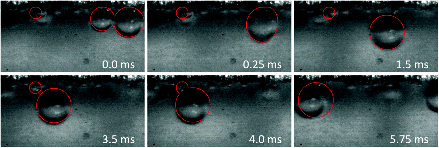 | ||
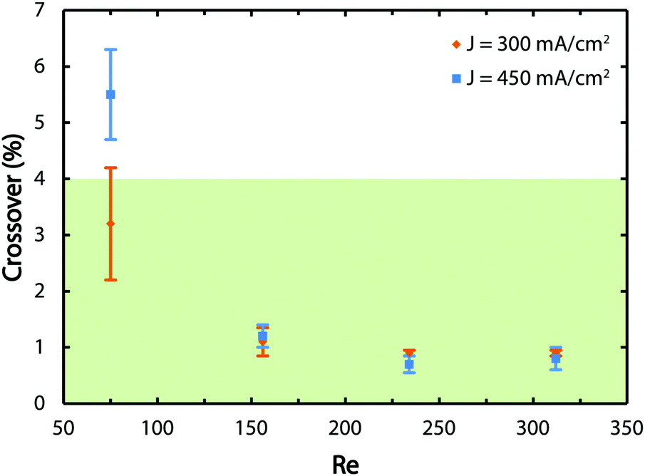
| Fig. 7 Snapshots from the experiment at Re = 234 overlaid by projections of the bubble shapes from the simulation (red lines). The flow direction is from right to left. All three bubbles are initially placed at the channel corner, with the smallest of the three further downstream than the others. Coalescence of the two larger bubbles causes the jump-off at t = 1.5 ms followed by a rapid return towards the electrode at t = 4.0 ms after coalescence with the smaller bubble. | ||
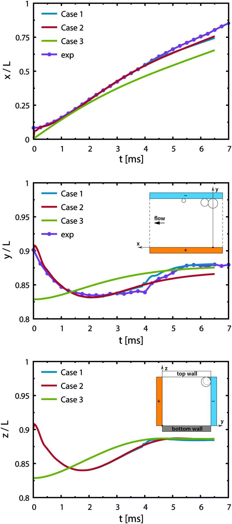 | ||
| Fig. 8 Trajectory of the newly formed bubble from simulations for various initial configurations. The curves indicate the position of the bubble's center of mass for three cases in the streamwise direction (x-axis), in between the electrodes (y-axis) and in the depth (z-axis) with time. The inset sketches of the middle and bottom figures illustrate the coordinate system from two views. Gravity acts towards the bottom wall (opposite to the z-axis). Case 1: two bubbles located upstream and a smaller bubble downstream as shown in Fig. 7, jump-off at t = 1.5 ms and rapid return at t = 4 ms after coalescence with the smaller bubble. Case 2: two bubbles, slower return caused by the inertial force and buoyancy. Case 3: a single bubble placed at a distance from the corner to reproduce conditions after the jump-off without having the disturbances in the flow caused by the coalescence. Experimental data (exp) correspond to Case 1. | ||
The return towards the wall starting before coalescence with the pinned bubble is attributed to inertial migration. It is observed in a simulation excluding the pinned bubble (Case 2) and one starting with a single bubble placed at a distance from the walls (Case 3); see Fig. 8. This shows that the inertial return is independent of coalescence. Interaction with the bubble pinned to the electrode causes a more rapid return: the walls induce a pressure field driving the liquid away from the wall.
Case 4 considers the jump-off starting with two bubbles as in Case 2 and additional Marangoni forces induced by the surface tension gradient prescribed in a boundary layer close to the electrode. The Marangoni effect can drive the return only if the thickness of the boundary layer exceeds the maximum distance from the wall after the jump-off which amounts to 0.06 mm, therefore the thickness is set to δ = 0.1 mm. The surface tension coefficient is uniform outside of the layer and decreases linearly from its edge towards the electrode. The gradient is estimated for hydrogen as 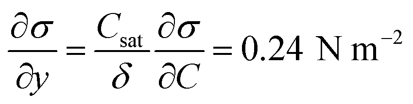 with Csat = 0.75 × 10⁻³ mol l−1 and
 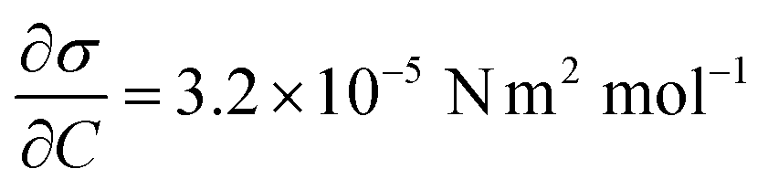 .70Fig. 9 presents trajectories from simulations at constant δ for different values of the gradient in the range between 0.024 and 24 N m−2.
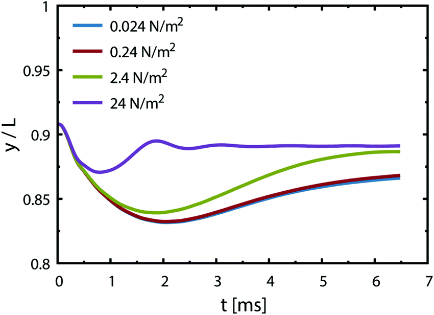 | ||
| Fig. 9 Trajectory of the newly formed bubble from simulations of Case 4, showing the effect of the Marangoni force. The curves represent the position of the bubble's center of mass in between the electrodes (y-axis) with time. Initial configuration consists of two bubbles placed at the corner as in Case 2. Various surface tension gradients are imposed within a boundary layer of thickness 0.1 mm starting from the electrode surface at y/L = 1 towards the center of the channel. The Marangoni force contribution is minimal compared to the inertial forces for small surface tension gradients. | ||
We note that the fastest acceleration of the main bubble is gained from the interaction with a smaller pinned bubble. Coalescence of bubbles is responsible for both the jump-off and the return while inertial migration causes the return at longer time scales. As evidenced from our simulations, the influence of the Marangoni force on the return phenomenon is rather negligible for the estimated value of the surface tension gradient (0.24 N m−2). Applying a ten times larger gradient makes the contribution of the Marangoni force comparable to that of the inertial force if we assume that the boundary layer thickness remains the same.
Besides the jump-off, coalescence results in formation of larger bubbles. These bubbles experience a larger buoyancy force that can potentially affect their trajectory. A simulation without considering the effect of gravity (based on Case 1 from Fig. 8) shows that for bubbles with 0.1 mm in radius, gravity plays a minimal role on deciding the final position of the bubbles (Fig. S4, ESI†).
Brine electrolysis
In the chlor-alkali process, a 20 wt% solution of sodium chloride is electrolyzed in the electrochemical cell to produce chlorine at the anode side, and NaOH and H2 at the cathode side. The polarization curve for this reaction using the current reactor for four different flow rates from 300 ml h−1 to 1200 ml h−1 is presented in Fig. 10. Similar to water splitting, the flow rate is positively correlated with the performance. The current density at 3.25 V increases from 593 mA cm−2 to 706 mA cm−2 by moving from the lowest tested flow rate to the highest flow rate at room temperature. The reasons behind this enhancement are the same as the ones given above for water splitting. The industrial membrane cells have similar characteristics,71 but at much higher working temperature of around 90 °C. Due to the incompatibility of the 3D printing material with this temperature, it is not possible to test the current device in such conditions. Nevertheless, much better performances are expected when testing this technology at operative standard temperatures. The main reason behind this improvement is that in the membrane cells, the interelectrode gap is in the range of few millimeters which is filled by the membrane and the electrolyte. In the 3D printed cell the membrane is replaced by the more conductive electrolyte and the interelectrode gap is reduced to 1 mm.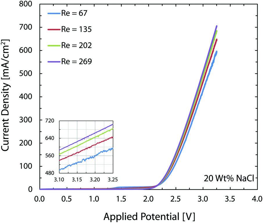 | ||
| Fig. 10 Polarization curves of the chlor-alkali reaction with 20 wt% NaCl electrolyte for different flow rates. Moving from the lowest to the highest Re enhances the current density by approximately 20% thanks to the lower gas volume fraction and lower catalyst coverage by nucleating bubbles. The performance of the cell at room temperature is similar to the state-of-the-art cells that operate at around 90 °C. The inset provides a detailed view of the data above 3.1 V. | ||
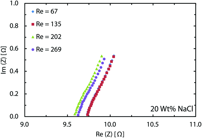
Like water splitting, PEIS measurements enable quantification of the ohmic drop in the NaCl solution. Fig. 11 shows an average value of 9.7 Ω, whereas the solution resistance based on the ionic conductivity of the 20 wt% NaCl solution, 0.226 S cm−1 at 25 °C,73 and cell dimensions should be 4.4 Ω. The 5.3 Ω difference between the two values is due to the ohmic contacts and is consistent with what described earlier for water splitting. As a result, at 700 mA cm−2, up to 370 mV of overpotential could be avoided if better ohmic contact is provided to the electrodes.
 | ||
| Fig. 11 PEIS measurements for the chlor-alkali reaction with 20 wt% NaCl electrolyte at different flow rates. Similar to the water splitting, better ohmic contacts can provide more than 300 mV reduction in the cell potential when working at around 700 mA cm−2. | ||
As mentioned earlier, in the brine electrolysis, the OER competes with the oxidation of chlorine ions. The portion of the current that goes into each reaction depends on the selectivity of the catalyst towards each of them. The DSA electrodes used here have excellent selectivity towards the desired chlorine evolution reaction and can be further optimized by acidification of the anolyte with HCl; a solution commonly used in the industry.71 Nevertheless, in the membrane-less cell, the Faradaic efficiencies need to be investigated, as we operate in different conditions than commercial brine electrolyzers: we do not acidify the electrolyte and, in addition, diffusion of hydroxide ions in our cell can be problematic. Faradaic efficiencies obtained from colorimetric comparison are provided in Fig. 12 for the anodic side's output. The same test has been done for the cathodic side's output and all of the values were below the detection limit of the comparator kit, i.e. 10 mg l−1. For both current densities, the Faradaic efficiency increases significantly by increasing the flow rate and reaches a value of more than 85% at the highest flow rate. Although the small measured values especially at lower flow rates might seem to be due to the enhanced rate of OER at first, considering the theoretical calculations provided earlier and the polarization curves of Fig. 12 necessitates a more careful investigation of this trend. First, the theoretical calculations predicted that this range of flow rates should be large enough to suppress the harmful transport of species such as the diffusion and migration of OH− ions towards the anode. Secondly, if the competing OER was the main reason behind the low current efficiencies at low flow rates, then the monotonic enhancement of current density with flow rate in Fig. 10 would be surprising since the water splitting reaction requires lower theoretical potential (1.23 V) compared to the brine electrolysis (2.19 V) and, therefore, the overall cell current would look different.
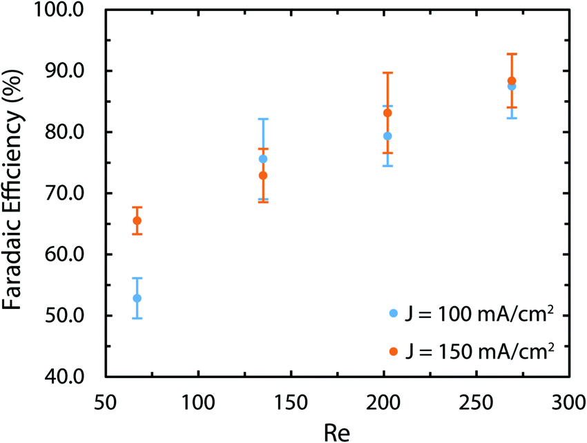 | ||
| Fig. 12 The Faradaic efficiency of the brine electrolysis at different current densities and flow rates measured with the colorimetry technic. The most likely reason for the low efficiency at low flow rates is the loss of Cl2 in gaseous form. The colorimetry method can only measure the amount of dissolved chlorine. This explanation is corroborated by the pH measurements provided in the ESI† that indicate Faradaic efficiencies of more than 88% for all sets of current densities and flow rates. | ||
In order to resolve this observation, we have measured the pH variations of the solution on both sides after the experiments. These results are provided in Fig. S5 and S6 (ESI†). More specifically, we have compared the pH variations on the cathode side with the ideal pH values that are calculated assuming a 100% Faradaic efficiency. Interestingly, using these ideal values and the measured pH values, the Faradaic efficiency is between 88 to 93% for all flow rates. As a result, the most likely reason behind the lower Faradaic efficiencies in Fig. 12 is the possible loss of chlorine in the gaseous form due to the chlorine saturation at the electrode–electrolyte interface, which is more relevant at lower flow rates.
Conclusion
We deploy stereolithography based additive manufacturing to develop a membrane-less electrolyzer with tight tolerances, smooth channel surfaces, and integrated ports. This reactor relies on inertial forces in the flow of highly conductive electrolytes for products separation and its performance has been analyzed for two critical electrochemical reactions: water splitting and the chlor-alkali process. We find the performance of the present reactor to compare well with that of the commercial reactors.We report two hydrodynamic mechanisms influencing the separation of gaseous products in flow-based cells: inertial migration and bubble coalescence. They are directly observed in the experiments and supported by numerical simulations. Marangoni forces contribute to the return of bubbles towards the electrode as well, but for the bubbles of the considered size have only secondary effects and stronger influence is expected for smaller bubbles.
The cell used in this study contains much larger electrodes than those previously reported in microfluidic reactors. We emphasize that although these sizes are not the upper limit in an effort to scale up the membrane-less technology, we expect the optimum dimensions to be in the same order of magnitude considering the flow conditions necessary for the products separation. For instance, the length of the channel can be increased as long as the largest bubble at the end of the channels does not become bigger than half of the channel's width and this can be controlled by the flow rate and current density. As illustrated in Fig. S7 (ESI†), parallelization and stacking of several optimized cells is the pathway towards higher throughputs. We estimate that decreasing the ohmic losses at the contacts can lead to an efficiency enhancement of 10–15% at a current density of around 500 mA cm−2. In addition, introduction of acidified anolytes through a second dedicated inlet will enhance the Faradaic efficiency in the brine electrolysis. Furthermore, printing with materials that endure high temperatures and pressures, enables the possibility to test the device at such temperatures (60 to 80 °C) and pressures (30 to 50 bars). In the membrane-less cell, only flow plates need to tolerate the high operating temperature and pressure since there is no membrane to undergo thermal and pressure induced stresses. Higher pressure also decreases the gas volume fraction which is a desirable factor in lowering down the losses in the interelectrode region. Catalysts with more active area compared to the current electrodes and with engineered nucleation sites72 can significantly boost the performance as well. The losses in the electrolyte can be minimized in two ways: employing sophisticated 3D printers to reduce the interelectrode gap to few hundreds of microns and using more conductive electrolytes such as 6 M KOH along compatible catalysts such as nickel. Upon such improvements, the membrane-less cell is expected to surpass the alkaline cells and approach the PEMs in terms of performance.
We believe that the present membrane-less reactor paves the way for realization of cost-effective and scalable electrochemical stacks that have the potential to revolutionize the renewable energy sector.
Conflicts of interest
There are no conflicts to declare.Acknowledgements
Professor Kevin Sivula and Professor Jeremy Luterbacher's groups were very kind and patient in giving us the access to their GC machines. Additive Manufacturing Workshop of EPFL assisted in the fabrication of the 3D printed part. Ursula Rasthofer cooperated at earlier stages of the project. The authors acknowledge the support from the grant no. “CRSII5_173860” of Swiss National Science Foundation and the grant no. “20NA21-145936” of Nano-Tera Initiative. PK, SL, and PK acknowledge the use of computing resources from CSCS (project s754).References
- S. Chu, Y. Cui and N. Liu, Nat. Mater., 2017, 16, 16–22 CrossRef PubMed.
- J. Andrews and B. Shabani, Int. J. Hydrogen Energy, 2012, 37, 1184–1203 CrossRef CAS.
- S. Ardo, D. F. Rivas, M. A. Modestino, V. S. Greiving, F. F. Abdi, E. A. Llado, V. Artero, K. Ayers, C. Battaglia, J. P. Becker, D. Bederak, A. Berger, F. Buda, E. Chinello, B. Dam, V. Di Palma, T. Edvinsson, K. Fujii, H. Gardeniers, H. Geerlings, S. M. H. Hashemi, S. Haussener, F. Houle, J. Huskens, B. D. James, K. Konrad, A. Kudo, P. P. Kunturu, D. Lohse, B. Mei, E. L. Miller, G. F. Moore, J. Muller, K. L. Orchard, T. E. Rosser, F. H. Saadi, J. W. Schuttauf, B. Seger, S. W. Sheehan, W. A. Smith, J. Spurgeon, M. H. Tang, R. van de Krol, P. C. K. Vesborg and P. Westerik, Energy Environ. Sci., 2018, 11, 2768–2783 RSC.
- X. N. Wang, H. Teichgraeber, A. Palazoglu and N. H. El-Farra, J. Process Control, 2014, 24, 1318–1327 CrossRef CAS.
- C. A. C. Sequeira and D. M. F. Santos, J. Braz. Chem. Soc., 2009, 20, 387–406 CAS.
- J. Crook and A. Mousavi, Environ. Forensics, 2016, 17, 211–217 CrossRef CAS.
- T. Momose, N. Higuchi, O. Arimoto, K. Yamaguchi and C. W. Walton, J. Electrochem. Soc., 1991, 138, 735–741 CAS.
- B. Rausch, M. D. Symes, G. Chisholm and L. Cronin, Science, 2014, 345, 1326–1330 CrossRef CAS PubMed.
- K. E. Ayers, E. B. Anderson, C. B. Capuano, B. D. Carter, L. T. Dalton, G. Hanlon, J. Manco and M. Niedzwiecki, ECS Trans., 2010, 33, 3–15 CAS.
- J. R. Varcoe, P. Atanassov, D. R. Dekel, A. M. Herring, M. A. Hickner, P. A. Kohl, A. R. Kucernak, W. E. Mustain, K. Nijmeijer, K. Scott, T. W. Xu and L. Zhuang, Energy Environ. Sci., 2014, 7, 3135–3191 CAS.
- K. Fu, Y. H. Gong, J. Q. Dai, A. Gong, X. G. Han, Y. G. Yao, C. W. Wang, Y. B. Wang, Y. N. Chen, C. Y. Yan, Y. J. Li, E. D. Wachsman and L. B. Hu, Proc. Natl. Acad. Sci. U. S. A., 2016, 113, 7094–7099 CrossRef CAS PubMed.
- B. E. Logan and M. Elimelech, Nature, 2012, 488, 313–319 CrossRef CAS PubMed.
- S. Z. Oener, S. Ardo and S. W. Boettcher, ACS Energy Lett., 2017, 2, 2625–2634 CrossRef CAS.
- M. A. Goulet and E. Kjeang, J. Power Sources, 2014, 260, 186–196 CrossRef CAS.
- J. W. Lee, M. A. Goulet and E. Kjeang, Lab Chip, 2013, 13, 2504–2507 RSC.
- S. A. M. Shaegh, N. T. Nguyen and S. H. Chan, Int. J. Hydrogen Energy, 2011, 36, 5675–5694 CrossRef.
- M. Safdar, J. Janis and S. Sanchez, Lab Chip, 2016, 16, 2754–2758 RSC.
- S. H. Lee and Y. Ahn, J. Power Sources, 2017, 351, 67–73 CrossRef CAS.
- H. Xu, H. Zhang, H. Z. Wang, D. Y. C. Leung, L. Zhang, J. Cao, K. Jiao and J. Xuan, Appl. Energy, 2015, 160, 930–936 CAS.
- E. Kjeang, R. Michel, D. A. Harrington, N. Djilali and D. Sinton, J. Am. Chem. Soc., 2008, 130, 4000–4006 CrossRef CAS PubMed.
- C. A. Martins, O. A. Ibrahim, P. Pei and E. Kjeang, Electrochim. Acta, 2018, 271, 537–543 CrossRef CAS.
- W. A. Braff, M. Z. Bazant and C. R. Buie, Nat. Commun., 2013, 4, 2346 CrossRef PubMed.
- R. S. Jayashree, M. Mitchell, D. Natarajan, L. J. Markoski and P. J. A. Kenis, Langmuir, 2007, 23, 6871–6874 CrossRef CAS PubMed.
- M. Hou, L. Chen, Z. Guo, X. Dong, Y. Wang and Y. Xia, Nat. Commun., 2018, 9, 438 CrossRef PubMed.
- M. A. Modestino, S. M. H. Hashemi and S. Haussener, Energy Environ. Sci., 2016, 9, 1533–1551 RSC.
- P. Hadikhani, S. M. H. Hashemi, G. Balestra, L. L. Zhu, M. A. Modestino, F. Gallaire and D. Psaltis, Lab Chip, 2018, 18, 1035–1046 RSC.
- S. M. H. Hashemi, M. Neuenschwander, P. Hadikhani, M. A. Modestino and D. Psaltis, J. Power Sources, 2017, 348, 212–218 CAS.
- H. Amini, W. Lee and D. D. Carlo, Lab Chip, 2014, 14, 2739–2761 RSC.
- D. Di Carlo, Lab Chip, 2009, 9, 3038–3046 RSC.
- S. M. H. Hashemi, M. A. Modestino and D. Psaltis, Energy Environ. Sci., 2015, 8, 2003–2009 RSC.
- M. I. Gillespie, F. van der Merwe and R. J. Kriel, J. Power Sources, 2015, 293, 228–235 CAS.
- G. D. O'Neil, C. D. Christian, D. E. Brown and D. V. Esposito, J. Electrochem. Soc., 2016, 163, F3012–F3019 Search PubMed.
- I. Holmes-Gentle, F. Hoffmann, C. A. Mesa and K. Hellgardt, Sustainable Energy Fuels, 2017, 1, 1184–1198 CAS.
- J. T. Davis, J. Qi, X. R. Fan, J. C. Bui and D. V. Esposito, Int. J. Hydrogen Energy, 2018, 43, 1224–1238 CAS.
- M. I. Gillespie and R. J. Kriek, J. Power Sources, 2017, 372, 252–259 CAS.
- D. V. Esposito, Joule, 2017, 1, 887 CrossRef.
- M. A. Modestino, D. F. Rivas, S. M. H. Hashemi, J. G. E. Gardeniers and D. Psaltis, Energy Environ. Sci., 2016, 9, 3381–3391 CAS.
- J. M. Pearce, Science, 2012, 337, 1303–1304 CAS.
- B. C. Gross, J. L. Erkal, S. Y. Lockwood, C. P. Chen and D. M. Spence, Anal. Chem., 2014, 86, 3240–3253 CrossRef CAS PubMed.
- T. Baden, A. M. Chagas, G. J. Gage, T. C. Marzullo, L. L. Prieto-Godino and T. Euler, PLoS Biol., 2015, 13, e1002086 CrossRef PubMed.
- E. MacDonald and R. J. S. Wicker, Science, 2016, 353, aaf2093 CrossRef CAS PubMed.
- A. Ambrosi and M. Pumera, Chem. Soc. Rev., 2016, 45, 2740–2755 RSC.
- L. Krejcova, L. Nejdl, M. A. M. Rodrigo, M. Zurek, M. Matousek, D. Hynek, O. Zitka, P. Kopel, V. Adam and R. Kizek, Biosens. Bioelectron., 2014, 54, 421–427 CrossRef CAS PubMed.
- A. Ambrosi, J. G. S. Moo and M. Pumera, Adv. Funct. Mater., 2016, 26, 698–703 CrossRef CAS.
- C. Zhao, C. Y. Wang, R. Gorkin, S. Beirne, K. W. Shu and G. G. Wallace, Electrochem. Commun., 2014, 41, 20–23 CrossRef CAS.
- K. Sun, T. S. Wei, B. Y. Ahn, J. Y. Seo, S. J. Dillon and J. A. Lewis, Adv. Mater., 2013, 25, 4539–4543 CrossRef CAS PubMed.
- G. Chisholm, P. J. Kitson, N. D. Kirkaldy, L. G. Bloor and L. Cronin, Energy Environ. Sci., 2014, 7, 3026–3032 RSC.
- Y. M. Wang, T. Voisin, J. T. McKeown, J. Ye, N. P. Calta, Z. Li, Z. Zeng, Y. Zhang, W. Chen, T. T. Roehling, R. T. Ott, M. K. Santala, P. J. Depond, M. J. Matthews, A. V. Hamza and T. Zhu, Nat. Mater., 2017, 17, 63 CrossRef PubMed.
- P. Boissonneau and P. Byrne, J. Appl. Electrochem., 2000, 30, 767–775 CrossRef CAS.
- J. P. Glas and J. W. Westwater, Int. J. Heat Mass Transfer, 1964, 7, 1427–1443 CrossRef CAS.
- D. E. Westerheide and J. W. Westwater, AIChE J., 1961, 7, 357–362 CrossRef CAS.
- R. P. Whitney and J. E. Vivian, Ind. Eng. Chem., 1941, 33, 741–744 CrossRef CAS.
- J. H. Ferziger and M. Peric, Computational methods for fluid dynamics, Springer Science & Business Media, 2012 Search PubMed.
- S. V. Patankar and D. B. Spalding, in Numerical Prediction of Flow, Heat Transfer, Turbulence and Combustion, ed. S. V. Patankar, A. Pollard, A. K. Singhal and S. P. Vanka, Pergamon, 1983, pp. 54–73, DOI:10.1016/B978-0-08-030937-8.50013-1.
- E. Aulisa, S. Manservisi, R. Scardovelli and S. Zaleski, J. Comput. Phys., 2007, 225, 2301–2319 CrossRef.
- J. U. Brackbill, D. B. Kothe and C. Zemach, J. Comput. Phys., 1992, 100, 335–354 CrossRef CAS.
- F. Wermelinger, U. Rasthofer, P. E. Hadjidoukas and P. Koumoutsakos, J. Comput. Methods Sci. Eng., 2018, 26, 217–225 Search PubMed.
- A. M. Soto, T. Maddalena, A. Raters, D. van der Meer and D. Lohse, J. Fluid Mech., 2018, 846, 143–165 CrossRef CAS.
- D. L. Wise and G. Houghton, Chem. Eng. Sci., 1966, 21, 999–1010 CrossRef CAS.
- A. Tang and O. C. Sandall, J. Chem. Eng. Data, 1985, 30, 189–191 CrossRef CAS.
- Solutions of electrolytes, https://people.ifm.liu.se/thoed/water/water-7.pdf.
- J. Rivero-Rodriguez and B. Scheid, J. Fluid Mech., 2018, 842, 215–247 CrossRef CAS.
- T. Groß, J. Bauer, G. Ludwig, D. F. Rivas and P. Pelz, Exp. Fluids, 2018, 59, 12 CrossRef.
- N. Nagai, M. Takeuchi and M. T. Furuta, Effects of bubbles between electrodes on alkaline water electrolysis efficiency under forced convection of electrolyte, Proceedings of 16th World Hydrogen Energy Conference, Lyon, 2006.
- E. Amores, J. Rodriguez, J. Oviedo and A. de Lucas-Consuegra, Open Eng., 2017, 7, 141–152 CAS.
- M. A. Modestino, K. A. Walczak, A. Berger, C. M. Evans, S. Haussener, C. Koval, J. S. Newman, J. W. Ager and R. A. Segalman, Energy Environ. Sci., 2014, 7, 297–301 RSC.
- R. Shandarr, C. A. Trudewind and P. Zapp, J. Cleaner Prod., 2014, 85, 151–163 CrossRef.
- H. E. Darling, J. Chem. Eng. Data, 1964, 9, 421–426 CrossRef CAS.
- S. Lubetkin, Electrochim. Acta, 2002, 48, 357–375 CrossRef CAS.
- X. Yang, D. Baczyzmalski, C. Cierpka, G. Mutschke and K. Eckert, Phys. Chem. Chem. Phys., 2018, 20, 11542–11548 RSC.
- R. K. B. Karlsson and A. Cornell, Chem. Rev., 2016, 116, 2982–3028 CrossRef CAS PubMed.
- P. van der Linde, P. Penas-Lopez, A. M. Soto, D. van der Meer, D. Lohse, H. Gardeniers and D. F. Rivas, Energy Environ. Sci., 2018, 11, 3452–3462 RSC.
- http://myweb.wit.edu/sandinic/Research/conductivity%20v%20concentration.pdf .
Footnote |
| † Electronic supplementary information (ESI) available. See DOI: 10.1039/c9ee00219g |
| This journal is © The Royal Society of Chemistry 2019 |