 Open Access Article
Creative Commons Attribution 3.0 Unported Licence
Alkali aluminosilicate geopolymers as binders to encapsulate strontium-selective titanate ion-exchangers
Xinyuan
Ke†
 *a,
Susan A.
Bernal‡
 a,
Tsutomu
Sato
b and
John L.
Provis
 *a
*a
aDepartment of Materials Science & Engineering, The University of Sheffield, Sheffield S1 3JD, UK. E-mail: x.ke@bath.ac.uk; j.provis@sheffield.ac.uk
bFaculty of Engineering, Hokkaido University, Sapporo, Hokkaido 060-0808, Japan
First published on 22nd July 2019
Abstract
Alkali-activated metakaolin geopolymers are attracting interest in the conditioning of nuclear wastes, especially for their ability to immobilise cationic species. However, there is limited understanding of the chemical interactions between the encapsulated spent ion-exchangers, used for decontaminating waste water, and the host aluminosilicate matrix. The lack of such understanding makes it difficult to predict the long-term stability of the waste form. In this study, the suitability of using metakaolin based geopolymer as a matrix for encapsulation of titanate-type ion-exchangers loaded with non-radioactive Sr was investigated for the first time, via spectroscopic and microstructural inspection of the encapsulated ion-exchangers and the aluminosilicate gel matrix. The microstructural and chemical properties of metakaolin geopolymers remained stable after encapsulating titanate type spent ion-exchangers, performed desirably as host materials for conditioning of Sr-loaded titanate ion-exchangers.
Introduction
Soon after the accident at the Fukushima Daiichi Nuclear Power Station on the 11th of March 2011, sea water was injected into the reactor core for emergency cooling.1 Water-soluble radionuclides such as 137Cs and 90Sr contaminated the cooling water, and were then removed during the following water treatment process by ion-selective inorganic resins.2,3 Alternative nanomaterials, such as functional carbon materials and metal–organic frameworks can also be used for removing radionuclides from waste water.4 The water treatment at the Fukushima Daiichi site is ongoing, and continues to generate spent ion exchange media that are loaded with radioisotopes.Sodium titanate, consisting of layered edge-sharing TiO6 octahedral chains linked with exchangeable interlayer sodium cations, was selected at the Fukushima Daiichi site for selective exchange of strontium ions from the waste water.5–9 An alkaline aqueous environment is preferred for the functionality of sodium titanate as an ion-exchanger, as in a non-basic aqueous environment (pH < 8), protonation of the surface cation-exchangeable site is preferred, which significantly reduces ion-exchange capacity.7
The spent ion-exchangers generated during the Fukushima Daiichi water decontamination processes need to be stabilised and disposed of as secondary nuclear wastes. The currently available options for management of these spent ion-exchangers include destructive methods, such as incineration and vitrification; and non-destructive methods, such as cementation.10 Most of the destructive methods involve thermal treatments, which unavoidably generate secondary off-gases that require additional processes for further decontamination. Cementation is instead a simple but robust option for conditioning nuclear wastes, especially for wastes with significant water content (e.g. wet granular ion-exchangers, slurries, etc.). There are numerous different cement systems that have been implemented or proposed to be used as waste forms, including Portland cement and its blends,11 calcium aluminate cement and its modifications with sulfate or phosphate,12,13 magnesium silicate or phosphate cement,14,15 as well as various types of alkali-activated cements.16–18
In choosing a suitable cement system for encapsulation of spent ion-exchangers, there are two important aspects to consider: firstly, the interactions between the ion-exchangers and the cement binder (chemical and dimensional stability); secondly, the partition (or redistribution) of radioelements between the spent ion-exchangers and the cement binder itself. A lower extent of interaction between the cement binder and the spent ion-exchangers would be preferred. The cement binder system should then have a high capacity to take up and/or absorb any radioelements that are released from the spent ion-exchangers, to prevent their further dispersion.19,20
In commonly used Portland cement–blended cement systems, the main mineral phases that immobilise radioelement ions are an aluminium substituted calcium silicate hydrate (C–(A)–S–H) type gel, ettringite (Ca6Al2(SO4)3(OH)12·26H2O), layered double hydroxides (LDHs, Me1−xAlx(OH)2(Am−)x/m·nH2O, where Me represents either Ca or Mg, and Am− commonly represents OH−, CO32−, or SO42−), and in some cases also polymorphs of CaCO3 (e.g. calcite, aragonite). However, among these, only CaCO3 is a highly favourable host for immobilisation of Sr2+ by forming (Ca,Sr)CO3 solid solutions.21 The other phases do not show such a high capacity/affinity to take up free Sr2+ from an aqueous phase.18,22,23 Also, in these high-Ca cement systems, the free Ca2+ in the pore solution might exchange with the Sr in the spent ion-exchanger,24 and thus release Sr2+ to the cement water.24 For this reason, it is desirable to seek cements that are not based on calcium, and so are less likely to cause strontium release from the encapsulated ion-exchanger.
The present study investigates geopolymer cements based on metakaolin. The binding phase in these cements is a monolithic alkali aluminosilicate type gel, which has attracted attention in nuclear waste conditioning due to its chemical and thermal resistance, and ability to immobilise hazardous cations.25–28 These gels consist of crystallographically disordered framework silicates (Q4) in tetrahedral environments, with a significant fraction of the Si sites substituted by Al,29 and are commonly prepared by activating aluminosilicate precursors (e.g. metakaolin or fly ash) with chemical activators (alkali hydroxide and/or silicate solutions).25 The Al substitution in Q4 sites is charge balanced by extra-framework cations, commonly Na+ and K+.29,30 As in zeolites, these extra-framework cations have the potential to be ion-exchanged by cations to be immobilised, including important radioelements (e.g.90Sr2+, 137Cs+).31–33 Studies using geopolymer binders to encapsulate zeolite-type ion-exchangers have shown that geopolymer waste forms were more mechanically durable and chemically stable than Portland cement-based waste forms,17,34,35 even though chemical interaction between the zeolite ion-exchangers and the gel binders was observed.17,34 However, there has not been any published study of the chemical and physical stability of geopolymer waste forms encapsulating titanate-type spent ion-exchangers.
This study presents detailed characterisation of metakaolin-based geopolymer waste forms encapsulating spent titanate ion-exchangers containing non-radioactive Sr. Two widely used activators, sodium silicate and potassium silicate, were used in preparing the gel binder. Based on the material characterisation results, the implications of the physicochemical interactions between the encapsulated ion-exchangers and the host geopolymer matrix on the chemical stability of the waste form is discussed.
Materials and methods
Simulated waste form
The commercial sodium titanate ion-exchanger SrTreat® (Fortum, Finland) was used in this study,36 with a chemical composition of Na0.6TiO2.2(OH)0.2·0.6H2O and grain size between 0.30 to 0.85 mm. The Sr-loaded sodium titanate was prepared by adding the ion-exchanger (as received) into 0.5 mol L−1 Sr(NO3)2 solution at a solid/liquid ratio of 1![[thin space (1/6-em)]](https://www.rsc.org/images/entities/char_2009.gif) :
:![[thin space (1/6-em)]](https://www.rsc.org/images/entities/char_2009.gif) 10 (g mL−1) in 250 mL HDPE bottles, and storing at 20 ± 2 °C for 3 days with regular shaking. Then, the solids were separated via filtration, and then dried at 80 °C in an oven overnight to remove free water. Analysis of the degree of ion exchange achieved is presented in the Results and Discussion section of this paper.
10 (g mL−1) in 250 mL HDPE bottles, and storing at 20 ± 2 °C for 3 days with regular shaking. Then, the solids were separated via filtration, and then dried at 80 °C in an oven overnight to remove free water. Analysis of the degree of ion exchange achieved is presented in the Results and Discussion section of this paper.
The alkali-activated metakaolin was prepared by mixing aqueous sodium silicate or potassium silicate with metakaolin (MetaStar 501, Imerys UK) to obtain a stoichiometry of M2O·Al2O3·3SiO2·11H2O, where M refers to either Na or K. This formulation was chosen according to previous studies in order to achieve dense and mechanically stable gel matrix.37 The activator solutions were prepared by dissolving NaOH (Honeywell Fluka, ≥98%) or KOH (Sigma-Aldrich, >90%) pellets to the commercial sodium silicate solution (SiO2/Na2O ratio of 2.0, water content of 56%) or potassium silicate (SiO2/K2O ratio of 2.5, water content of 15%) supplied by PQ Corporation. The activator solution constituents were blended to give a dissolved SiO2/M2O molar ratio of 1.0. The required amount of Milli-Q water was added to the alkali-activator solution to obtain a constant M2O/H2O ratio in each sample. The sodium silicate-activated metakaolin samples are denoted Na-GP, and the potassium silicate-activated metakaolin samples are denoted K-GP. The simulated waste forms were prepared by firstly dry-mixing the Sr-loaded titanate with alkali-activated metakaolin gel binders, with a mass ratio of spent ion-exchanger to metakaolin precursor of 1![[thin space (1/6-em)]](https://www.rsc.org/images/entities/char_2009.gif) :
:![[thin space (1/6-em)]](https://www.rsc.org/images/entities/char_2009.gif) 10, and then adding the pre-prepared alkali-activator to the dry mix to form fluid pastes. The mixtures were blended using a high shear overhead mixer, cast and sealed in centrifuge tubes, and stored at 20 ± 2 °C for 1 month prior to analysis.
10, and then adding the pre-prepared alkali-activator to the dry mix to form fluid pastes. The mixtures were blended using a high shear overhead mixer, cast and sealed in centrifuge tubes, and stored at 20 ± 2 °C for 1 month prior to analysis.
SEM-EDX
After one month of aging, the simulated geopolymer waste forms were sliced into 5 mm sample discs (Φ 14 mm), mounted onto an aluminium sample stand, and polished using diamond paste to 0.25 μm fineness. The polished sample surface was then analysed by moderate-vacuum scanning electron microscopy (SEM) for backscattered electron imaging, and energy dispersive X-ray spectroscopy (EDX) for elemental analysis, both using a Hitachi benchtop ESEM TM3030 coupled with a Bruker Quantax 70 X-ray microanalysis detector. An acceleration voltage of 15 kV and a working distance of 10 mm were applied.Raman spectroscopy
Sliced solid samples were also used for Raman spectroscopy analysis, following the same preparation methods as for SEM-EDX. Raman spectra were recorded with a Renishaw Invia Raman spectrometer equipped with a CCD detector, using a green line (514.5 nm) laser at 20 mW laser power and a 50× objective. The samples were scanned between 100 cm−1 and 1200 cm−1, with a 10 s exposure time for each sample. Calibration with silicon was undertaken each time the spectrometer was used.X-ray diffraction (XRD) and X-ray fluorescence (XRF)
The crystalline structure and chemical composition of the sodium titanate used in this study, before and after Sr-exchange, were characterised using XRD and XRF. A Panalytical X'Pert3 Powder X-ray diffractometer, with Cu Kα radiation and a nickel filter, was used for XRD. The tests were conducted with a step size of 0.02° and a counting time of 0.5 s per step, from 5° to 55° 2θ. A Panalytical Zetium Wavelength Dispersive X-ray Fluorescence (XRF) Analyser was used for XRF, with a 4 kW rhodium X-ray source. The fused bead method was used for sample preparation, mixing around 1 g of powdered sample with about 10 g of flux (99.5% Li2B4O7 + 0.5% LiI), which was then fused at 1065 °C, moulded in a platinum crucible and air-cooled to room temperature before testing.Results and discussion
Sr-loaded titanate and geopolymer binders
Fig. 1 shows the X-ray diffraction pattern of the metakaolin precursor and the plain Na-geopolymer and K-geopolymer binders (without spent ion-exchangers) stored at 20 ± 2 °C for 1 month. Crystalline anatase (TiO2, Powder Diffraction File (PDF) # 01-084-1286) and quartz (SiO2, PDF# 01-078-2315) were observed from the metakaolin precursor, which stayed as inert phases in the alkali-activated metakaolin gel binder. A trace of hydroxylated muscovite (a mica-group mineral, PDF# 00-026-0911) was also observed in the metakaolin precursor; however, it reacted with the activator to be incorporated into the alkali aluminosilicate gel binder. The main alkali (Na or K) aluminosilicate gel was observed through a broad non-crystalline feature centred at around 28° 2θ, suggesting the formation of a relatively homogeneous gel.38,39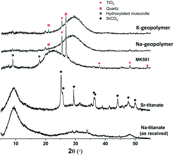 | ||
| Fig. 1 XRD patterns of metakaolin precursor (MK501), plain geopolymer binders (Na-geopolymer and K-geopolymer) and titanate ion-exchangers before (Na-titanate) and after Sr-exchange (Sr-titanate). | ||
The XRD pattern (Fig. 1) of the as-received titanate ion-exchanger showed the material to be apparently semi-crystalline, with a large diffuse scattering centred at around 9.4° 2θ, corresponding to an average interlayer spacing of around 9.4 Å for diffraction of Cu Kα radiation. This value is somewhat larger than the layer spacing between the main edge-sharing TiO6 sheets reported for sodium titanate nanosheets, Na4Ti9O20·nH2O, with an average interlayer spacing of 8.8 Å.8 After ion-exchange with Sr2+, the crystallinity of the titanate did not change significantly, but the formation of a fraction of SrCO3 crystals was observed, likely due to the partial surface carbonation when dried in air.6 According to the XRF analysis of the ion-exchangers (Table 1), the simulated spent ion-exchanger contained 11 wt% SrO. The total loss on ignition (L.O.I.) is higher for titanate ion-exchanged by Sr, likely related to the formation of SrCO3 which decomposes at around 800 °C.40 The results shown in Table 1 suggest an Na/Ti molar ratio of 0.61 for the as-received titanate, and a Na/Ti molar ratio of 0.35 together with a Sr/Ti molar ratio of 0.13 for the Sr-exchanged titanate. The total (2Sr + Na)/Ti ratio (0.61) was not changed before and after Sr-exchange, indicating an exchange extent of 42.6% of the total exchangeable Na+ sites.
| wt% | TiO2 | Na2O | SrO | Other | L.O.I. |
|---|---|---|---|---|---|
| As received | 68.6 | 16.2 | 0.0 | 0.2 | 14.9 |
| Sr-Exchanged | 64.5 | 8.7 | 11.1 | 0.2 | 15.3 |
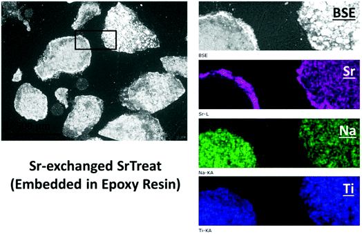
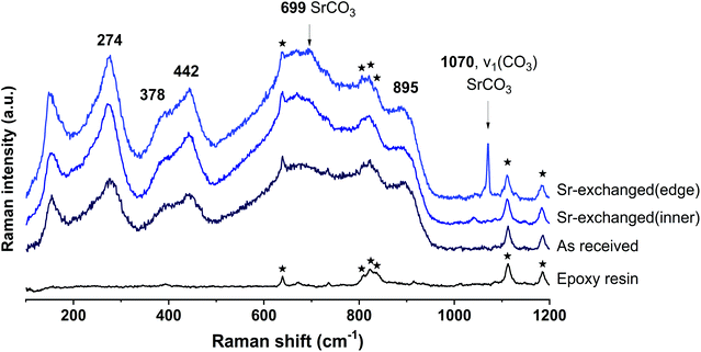
The SEM-BSE images of the cross-section of Sr-exchanged titanate (Fig. 2) show Sr-rich regions surrounding the surface of titanate, while the distribution of Sr element within the ion-exchangers appears to be uniformly distributed. Fig. 3 shows the Raman spectra taken from the same sample at different locations: the edge (Sr-rich) and the inner region of the ion-exchanger. These results were compared to the Raman spectra taken from the as-received titanate ion-exchanger, and the epoxy resin (containing no samples). It appears that, the Sr-rich region on the surface of the titanate was due to the formation of crystallised SrCO3, as suggested by the sharp and intense peak at 1070 cm−1, corresponding to the C![[double bond, length as m-dash]](https://www.rsc.org/images/entities/char_e001.gif) O stretching vibration of carbonates.41
O stretching vibration of carbonates.41
According to the literature,42–46 Raman shifts between 600–700 cm−1 correspond to edge-shared TiO6 (similar to anatase and rutile), those between 700–800 cm−1 correspond to the Ti–O–Ti stretch vibration in regular corner-shared TiO6 chains, 800–900 cm−1 indicates the Ti![[double bond, length as m-dash]](https://www.rsc.org/images/entities/char_e001.gif) O bond in TiO5, and the stretching vibration of Si–O–Ti bonds appear at between 900–1000 cm−1, predominantly at 960 cm−1. The Raman shifts below 600 cm−1 are mostly related to surface Ti–O–(H, Na, K, Sr) bonds.45,46 In Fig. 3, the chemical shifts corresponding the these Ti–O and Ti
O bond in TiO5, and the stretching vibration of Si–O–Ti bonds appear at between 900–1000 cm−1, predominantly at 960 cm−1. The Raman shifts below 600 cm−1 are mostly related to surface Ti–O–(H, Na, K, Sr) bonds.45,46 In Fig. 3, the chemical shifts corresponding the these Ti–O and Ti![[double bond, length as m-dash]](https://www.rsc.org/images/entities/char_e001.gif) O bonds have not changed significantly after ion-exchange, suggesting that the uptake of Sr2+ by titanate will not change the framework structure of titanate. This provides important reference for latter discussion on the effects of using geopolymer for encapsulating these spent ion-exchangers.
O bonds have not changed significantly after ion-exchange, suggesting that the uptake of Sr2+ by titanate will not change the framework structure of titanate. This provides important reference for latter discussion on the effects of using geopolymer for encapsulating these spent ion-exchangers.
Interfaces between geopolymer and encapsulated Sr-loaded sodium titanate
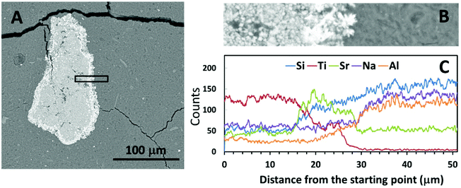
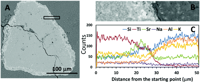
Fig. 4 and 5 show SEM-BSE images of cross-sections of the simulated waste forms with encapsulated titanate particles, and a line scan of the intersection between the titanate granules and each of the geopolymer binders, which were prepared using different activators. In Fig. 4A and 5A, the darker grey regions represent the main alkali aluminosilicate gel binder, and the granular shaped light grey regions with bright white rings represent the spent titanate ion-exchangers. From these images, it appears that apart from drying cracks present in the binder due to imaging under partial vacuum, there have been no significant dimensional changes in either the titanate ion-exchanger or the geopolymer binder after setting that would lead to damage to the matrix. Such damage would have been expected to appear as cracks radiating from the encapsulated particle (if an expansive reaction was induced in the ion exchanger, or shrinkage induced in the geopolymer gel), or as crack formation within the encapsulated particle or along the interface (if the particle had shrunk or the binder expanded).Fig. 4C and 5C show the EDX line scans of the regions shown in Fig. 4B and 5B. As indicated by the line scan data for Ti, there appeared to be a clear boundary between the encapsulated ion-exchanger and the geopolymer binder. From the line scan data for Sr, the exchanged Sr appeared to have accumulated at the surface of the IE particle, as in the ion-exchanged Sr-titanate before encapsulation (Fig. 2). The Sr-rich region surrounding the IE is likely to contain the SrCO3 observed by XRD (Fig. 1), as well as exchanged ions. Although Al and Si were only sourced from the alkali aluminosilicate binder, the line scans of these two elements showed that they might also present in the inner regions of ion-exchanger particles, suggesting that the binder material might have penetrated into these particles, potentially by being absorbed into the oven-dried particles in the early stage of the reaction.
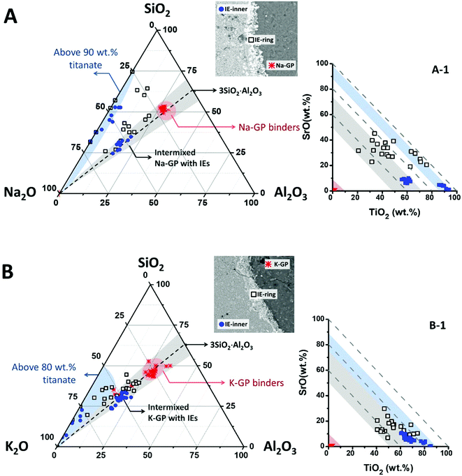
To illustrate the compositions of these intermixed aluminosilicate phases within the ion-exchangers, EDX data points taken from the geopolymer binders, the outer (marked as IE-ring) and the inner (marked as IE-inner) regions of the encapsulated ion-exchangers have been plotted in the Na2O–Al2O3–SiO2 pseudo-ternary diagram (renormalised to exclude TiO2 and SrO2) for the Na-GP waste form (Fig. 6A), and the K2O–Al2O3–SiO2 pseudo-ternary (renormalised to exclude Na2O, TiO2 and SrO2) for the K-GP waste form (Fig. 6B). The black dashed lines in these plots represent alkali aluminosilicate gel compositions with a fixed Si/Al molar ratio of 1.5, the same as the Si/Al ratio of the geopolymer binder in each case. The red regions in these plots cover the data points taken from the geopolymer binders. The areas shaded in grey correspond to regions where the bulk Si/Al ratio is in the range 1.5 ± 0.3, and the light blue shading highlights the data clusters of high overall TiO2 + SrO content. The inset plots Fig. 6A-1 and B-1 show the mass percentages of TiO2vs. SrO (with respect to the total detected elements) for the same data points shown in the ternary diagrams, where the dashed guidelines are used to indicate constant total mass percentages of (TiO2 + SrO). The regions shaded in red, blue and grey correspond to the similarly-shaded regions in Fig. 6A and B respectively.
The inner sections of the encapsulated ion-exchanger particles in both Na-GP (Fig. 6A) and K-GP (Fig. 6B) waste forms are composed of two distinct regions: the regions where alkali aluminosilicate gel is intermixed with alkali titanate (grey region); and the titanate-dominated regions (blue). The alkali (Na or K) aluminosilicate gel found within the inner section of the Sr-exchanged titanate exhibited a similar bulk Si/Al ratio to the main geopolymer binder (grey regions), for both activator types. This suggests that in both Na-GP and K-GP waste forms, there might be up to 50 wt% (as indicated by Fig. 6A-1 and B-1) geopolymer binder intimately intermixed with the ion-exchanger. However, different features were observed from these two types of waste forms within the titanate-dominated region (blue regions). For the Na-GP waste form (Fig. 6A), the titanate-dominated region was mixed with less than 10 wt% sodium silicate with SiO2/Na2O molar ratios varying from 0.5 to 3.0. The Al2O3 content within this region is negligible. In the K-GP waste form (Fig. 6B), the titanate-dominated region was primarily mixed with K2O-rich phases, up to 20 wt%. The Al2O3 content within this region can still be considered negligible. However, the relative SiO2 content was significantly lower in comparison with the Na-GP waste form, with SiO2/K2O molar ratios varying from 0 to 1.5. Since the titanate ion-exchanger contains no K2O as received, the K2O present within the ion-exchanger must have been brought in by the potassium silicate activator. Therefore, as suggested by the identification of a dominant K2O–TiO2–SrO region (lower left corner in the blue region, Fig. 6B), formation of potassium titanate within the ion-exchanger region might take place, due to the uptake of some vacant exchangeable sites by free K+.
Also, the scattered data points observed between the grey and blue regions were showed only for the Na-GP waste form, suggesting that, other than the main alkali aluminosilicate hydrate gels, there might be Si-rich phases formed near the surface of the ion-exchangers. This can be caused by either trapping of alkali silicate activators near the surface at the initial stage of the activation, and/or the formation of titanosilicates that contain Si–O–Ti chemical bonds. The presence of such bonds would indicate chemical reactivity between the encapsulated particles and the geopolymer binder. However, the latter possibility needs to be further discussed from the basis of the Ti–O chemical bond environment within the geopolymer waste forms. In addition, there might also be coexisting strontium silicate hydrate, Sr5Si6O16(OH)2·5H2O, within this region; such a phase has previously been observed to form in Sr2+-rich siliceous alkaline solution at pH ∼ 12.47 The strontium silicate hydrate formed under these conditions presented a semi-crystallised structure similar to tobermorite, Ca5Si6O16(OH)2·4H2O, in which most of the silicate is in the Q2 chain sites.48 As the main alkali aluminosilicate gel contains predominately Q4 tetrahedral silica species, the chemical bonding environment of the Q2 bridging silicates might be used as an indication of the presence of this phase.
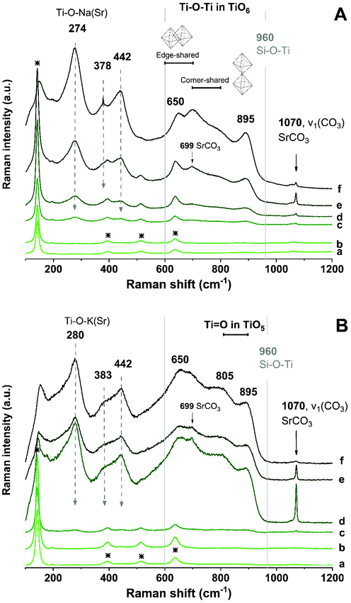
Raman spectroscopy was used to identify the Ti–O chemical bonds and other chemical environments in the geopolymer waste forms. Fig. 7 shows the Raman spectra taken from different locations in the waste forms: the bulk geopolymer binder, crossing the ring section, and toward the inside of the encapsulated ion-exchanger particle. In the bulk geopolymer binder region of both Na-GP (Fig. 7A) and K-GP (Fig. 7B) samples, Raman shifts were observed at 144, 397, 516, and 639 cm−1, matching the spectrum of anatase,49 which was a impurity in the metakaolin precursor (Fig. 1). Although the alkali aluminosilicate gel is the main constituent of the gel binder, no Raman signals corresponding to the Si–O–(Al, Si) bonds (at around 900–1200 cm−1 (ref. 50)) have been identified. However, since the intensity of Raman peaks is influenced by both concentration and structural ordering, disordered structures such as alkali aluminosilicate geopolymer gels would be expected to show weak Raman bands.51
In the outer ring of the ion-exchangers, peaks at around 274 cm−1 (280 cm−1 for K-GP), 378 cm−1, 442 cm−1, 650 cm−1, and 895 cm−1 start to appear, the intensities of which increase when moving towards the inner region of the ion-exchanger particles. The locations of these peaks corresponded to those observed for the as-received sodium titanate ion-exchangers (Fig. 3), and may represent a layer-like structure containing titanate nanotube-like environments.43 However, alterations in the Ti–O chemical bonding environment of the encapsulated ion-exchangers have been observed, involving both surface Ti–O–(H, Na, K, Sr) bonds and the main titanate layers. The Raman shift corresponding to the surface Ti–O–(H, Na, K, Sr) bonds moved towards higher wavenumbers in Fig. 7B, suggesting that bonding involves cations with stronger ionic interactions (e.g. K+ and Sr2+),24,52 consistent with the hypothesis that the surface Ti–O bonds in the K-GP waste form might be significantly charge-balanced by K+ from the activator.
A new Raman peak at around 702 cm−1 appeared from the ion-exchanger encapsulated in the Na-GP, corresponding to the Ti–O–Ti bond in corner-shared TiO6; while a new Raman peak at around 805 cm−1 was observed from the ion-exchanger encapsulated in the K-GP, corresponding to the Ti![[double bond, length as m-dash]](https://www.rsc.org/images/entities/char_e001.gif) O bond in TiO5. However, neither in Fig. 7A nor in Fig. 7B was there a Raman peak associated with Si–O–Ti bonding (960 cm−1 (ref. 44)). This suggests that, although the encapsulated ion-exchangers underwent structural distortion in their main titanate layers, the chemical interactions between the encapsulated titanate ion-exchanger and the geopolymer binder were not extensive as no chemical bonds associated with titanosilicates were formed. An additional sharp and intense peak was observed at 1070 cm−1 in the Sr-rich outer ring of the ion-exchanger encapsulated in both Na-GP and K-GP, corresponding to the C
O bond in TiO5. However, neither in Fig. 7A nor in Fig. 7B was there a Raman peak associated with Si–O–Ti bonding (960 cm−1 (ref. 44)). This suggests that, although the encapsulated ion-exchangers underwent structural distortion in their main titanate layers, the chemical interactions between the encapsulated titanate ion-exchanger and the geopolymer binder were not extensive as no chemical bonds associated with titanosilicates were formed. An additional sharp and intense peak was observed at 1070 cm−1 in the Sr-rich outer ring of the ion-exchanger encapsulated in both Na-GP and K-GP, corresponding to the C![[double bond, length as m-dash]](https://www.rsc.org/images/entities/char_e001.gif) O stretching vibration of carbonates,41 same as that been observed from the ion-exchangers before encapsulation in geopolymer (Fig. 3). This peak decreased in the inner region of the ion-exchanger particles, confirming that the SrCO3 had accumulated mainly in the outer ring of the Sr-exchanged particles.
O stretching vibration of carbonates,41 same as that been observed from the ion-exchangers before encapsulation in geopolymer (Fig. 3). This peak decreased in the inner region of the ion-exchanger particles, confirming that the SrCO3 had accumulated mainly in the outer ring of the Sr-exchanged particles.
The Raman spectrum of a pure strontium silicate hydrate phase is not available from literature. However, the analogous tobermorite-like calcium silicate hydrate phase gives two distinctive Raman peaks, at 671 and 1020 cm−1, attributed to symmetrical bending and symmetrical stretching of Si–O–Si bands within the Q2 silicate chains.53 Comparison between the Raman spectra of calcium silicate and strontium silicate glasses (synthesised by high-energy milling) showed almost identical results, both of which featured the symmetrical Si–O–Si stretching band at around 1050 cm−1.54 Due to the similarity between the crystalline structures of these two phases, it would be within reason to assume that strontium silicate hydrate would contribute to comparable Raman peaks. However, neither of these two Raman peaks identified as being distinctive of the tobermorite-like structure (671 and 1020 cm−1) can be observed in Fig. 7. Also, it has been proven that in the hydrous Na2O–CaO–Al2O3–SiO2 gel system, the formation of (Al-substituted) calcium silicate hydrate gels of tobermorite-like structure was barely observed in samples with CaO lower than 10 wt%.55 For comparison, in the simulated waste forms prepared for this study, the overall SrO mass percentages in Na-GP and K-GP are 0.72 wt% and 0.65 wt%, respectively. Observations from previous studies suggested that Sr2+ behaved comparably to Ca2+ as a structure orienting cation for geopolymers.56 On this basis, the formation of strontium silicate hydrate in the simulated waste forms tested here would be highly unlikely.
Perspectives
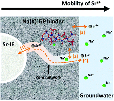
The physical and chemical interactions between the encapsulated ion-exchangers and the geopolymer host matrix play important roles in determining the long-term chemical stability of the designed waste forms. The mobility of Sr2+ within the waste form is one of the most important aspects to consider when assessing its long-term chemical stability, which involves multiple physical and chemical processes including leaching (which is not addressed directly in the current study). As illustrated in Fig. 8, these processes can be summarised as ionic interaction at the solid-solution interfaces ([1]–[3] in Fig. 8) and ionic diffusion in the pore solution ([4] in Fig. 8). The microstructure and the gel chemistry properties of the geopolymer binder, including the pore size distribution, the pore connectivity, the aluminosilicate framework structure, and the co-existing ions and prevailing pH conditions in the pore solution, all play critical roles in these processes.The physicochemical interactions between the encapsulated ion-exchangers and the host geopolymer matrix largely determine the ion exchange process marked as [1] in Fig. 8, which is the release of Sr2+ from the exchanger particles. The experimental results obtained in this study suggest that the titanate ion-exchangers mostly maintained their original physical and chemical properties after having been encapsulated in geopolymers. Therefore, it is reasonable to assume that this ionic interaction process would be primarily be restricted by the reversibility of the Sr-selective ion-exchange process in the presence of geopolymer pore solution. The pore solution in metakaolin-based geopolymers contains approximately 1 mol L−1 alkali hydroxides.57 For titanate type ion-exchangers, their selectivity for Sr2+ is particularly high in alkali aqueous media (pH > 12),8,24,58 and the uptake of Sr2+ will be preferred even in solutions that are very rich in Na+ and/or K+ (up to 10 mol L−1).5,6,24 The equilibrium constant (Keq) for Sr2+ uptake by sodium titanate under an alkaline, Na+ rich environment was reported to be between 2 × 10⁷ to 2 × 10⁸ 5, suggesting that the reverse reaction of this selective exchange process would be very limited in the geopolymer waste form.
The exchange process is also strongly affected by the concentration of divalent cations, such as Ca2+ and Mg2+.24 This further highlights the benefit of using low-calcium, low-magnesium geopolymer gel binders for encapsulation of these spent ion-exchangers, and the very high geopolymer pore fluid pH further suppresses the dissolved concentrations of these ions even if they are present. Since Sr2+ uptake by sodium titanate is pH-dependent, the use of low alkalinity cements would not be as desirable as geopolymers. In addition, the small amount of Sr2+ ions released from the ion-exchanger through the reversed ion-exchange process can then be immobilised by the geopolymer if they do gain any mobility within the binder matrix (process marked as [2] in Fig. 8), either through ion-exchange with the extra-framework cations59,60 or through forming non-reversible inner-sphere adsorption complexes.61 According to such considerations, the overall leachability of Sr2+ of this geopolymer waste form would be expected to be even lower.
The results from this study provide detailed insight into the physicochemical interactions between encapsulated ion-exchangers and the host geopolymer matrix, from elemental distribution to atomic interactions. This understanding will provide indispensable support for future analysis of the macroscale engineering properties, such as mechanical strength and leachability, of the bulk geopolymer waste forms with encapsulated titanate ion-exchangers.
Conclusions
Metakaolin geopolymers, consisting mainly of alkali aluminosilicate gel, show highly desirable performance as binders to encapsulate spent titanate ion-exchangers, simulating those which are loaded with radioactive strontium through water treatment operations at the Fukushima Daiichi site. The resulting waste forms are stable in both microstructural and chemical properties. The encapsulated titanate ion-exchangers were in intimate contact with the alkali aluminosilicate gel binder which also filled in the space within the ion-exchangers, contributing to a dense microstructure in the waste form. The choice of either sodium or potassium as the activator for geopolymer synthesis led to slight alterations in the octahedral titanate coordination in the main titanate sheet of the ion-exchangers. However, the overall chemical interactions between alkali aluminosilicate gel binder and the titanate ion-exchangers did not appear to be significant, as evidenced by the absence of Ti–O–Si bond formation in the samples tested here.Conflicts of interest
There are no conflicts of interest to declare.Acknowledgements
This work was funded by the EPSRC-Japan Civil Nuclear Collaboration programme, grant EP/P013171/1, between the University of Sheffield and Hokkaido University. This research was performed in part at the MIDAS Facility, at the University of Sheffield, which was established with support from the Department of Energy and Climate Change. The authors would like to thank Fortum for supplying the ion exchangers for this study, and PQ Corporation and Imerys for supplying sodium silicate and metakaolin, respectively.References
- T. Shibata, H. Solo-Gabriele and T. Hata, Environ. Sci. Technol., 2012, 46, 3618–3624 CrossRef CAS.
- A. Kirishima, T. Sasaki and N. Sato, J. Nucl. Sci. Technol., 2015, 52, 152–161 CrossRef CAS.
- The Council for the Decommissioning of TEPCO's Fukushima Daiichi Nuclear Power Plant, Summary of decommissioning and contaminated water management, http://www.tepco.co.jp/en/nu/fukushima-np/roadmap/images/d170928_01-e.pdf.
- X. Wang, L. Chen, L. Wang, Q. Fan, D. Pan, J. Li, F. Chi, Y. Xie, S. Yu, C. Xiao, F. Luo, J. Wang, X. Wang, C. Chen, W. Wu, W. Shi, S. Wang and X. Wang, Sci. China: Chem., 2019, 62 DOI:10.1007/s11426-019-9492-4 , in press.
- A. Villard, B. Siboulet, G. Toquer, A. Merceille, A. Grandjean and J.-F. Dufrêche, J. Hazard. Mater., 2015, 283, 432–438 CrossRef CAS.
- O. Oleksiienko, I. Levchuk, M. Sitarz, S. Meleshevych, V. Strelko and M. Sillanpää, J. Colloid Interface Sci., 2015, 438, 159–168 CrossRef CAS.
- J. Lehto, R. Harjula and A.-M. Girard, J. Chem. Soc., Dalton Trans., 1989, 1, 101–103 RSC.
- J. Lehto and A. Clearfield, J. Radioanal. Nucl. Chem., 1987, 118, 1–13 CrossRef CAS.
- A. Clearfield and J. Lehto, J. Solid State Chem., 1988, 73, 98–106 CrossRef CAS.
- International Atomic Energy Agency, Application of ion exchange processes for treatment of radioactive waste and management of spent ion exchangers, IAEA, Vienna, 2002 Search PubMed.
- W. Gashier, T. Miura, K. Hashimoto, R. J. Hand and H. Kinoshita, Adv. Appl. Ceram., 2014, 113, 447–452 CrossRef CAS.
- I. Garcia-Lodeiro, K. Irisawa, F. Jin, Y. Meguro and H. Kinoshita, Cem. Concr. Res., 2018, 109, 243–253 CrossRef CAS.
- C. Cau-dit-Coumes, in Cement-Based Materials for Nuclear Waste Storage, ed. F. Bart, C. Cau-di-Coumes, F. Frizon and S. Lorente, Springer New York, New York, NY, 2013, pp. 171–191 Search PubMed.
- T. Zhang, C. R. Cheeseman and L. J. Vandeperre, Cem. Concr. Res., 2011, 41, 439–442 CrossRef CAS.
- C. Cau-dit-Coumes, D. Lambertin, H. Lahalle, P. Antonucci, C. Cannes and S. Delpech, J. Nucl. Mater., 2014, 453, 31–40 CrossRef CAS.
- C. Shi and A. Fernández-Jiménez, J. Hazard. Mater., 2006, 137, 1656–1663 CrossRef CAS PubMed.
- C. Kuenzel, J. F. Cisneros, T. P. Neville, L. J. Vandeperre, S. J. R. Simons, J. Bensted and C. R. Cheeseman, J. Nucl. Mater., 2015, 466, 94–99 CrossRef CAS.
- N. Mobasher, S. A. Bernal, H. Kinoshita and J. L. Provis, J. Nucl. Mater., 2016, 482, 266–277 CrossRef CAS.
- N. D. M. Evans, Cem. Concr. Res., 2008, 38, 543–553 CrossRef CAS.
- D. A. Kulik, Rev. Mineral. Geochem., 2009, 70, 125–180 CrossRef CAS.
- W. Dong and S. C. Brooks, Environ. Sci. Technol., 2006, 40, 4689–4695 CrossRef CAS PubMed.
- D. A. Kulik, V. L. Vinograd, N. Paulsen and B. Winkler, Phys. Chem. Earth, 2010, 35, 217–232 CrossRef.
- J. Tits, E. Wieland, C. J. Müller, C. Landesman and M. H. Bradbury, J. Colloid Interface Sci., 2006, 300, 78–87 CrossRef CAS.
- J. Ryu, S. Kim, H.-J. Hong, J. Hong, M. Kim, T. Ryu, I.-S. Park, K.-S. Chung, J. S. Jang and B.-G. Kim, Chem. Eng. J., 2016, 304, 503–510 CrossRef CAS.
- J. L. Provis and S. A. Bernal, Annu. Rev. Mater. Res., 2014, 44, 299–327 CrossRef CAS.
- M. G. Blackford, J. V. Hanna, K. J. Pike, E. R. Vance and D. S. Perera, J. Am. Ceram. Soc., 2007, 90, 1193–1199 CrossRef CAS.
- M. Arbel Haddad, E. Ofer-Rozovsky, G. Bar-Nes, E. J. C. Borojovich, A. Nikolski, D. Mogiliansky and A. Katz, J. Nucl. Mater., 2017, 493, 168–179 CrossRef CAS.
- M. Y. Khalil and E. Merz, J. Nucl. Mater., 1994, 211, 141–148 CrossRef CAS.
- P. Duxson, J. L. Provis, G. C. Lukey, F. Separovic and J. S. J. van Deventer, Langmuir, 2005, 21, 3028–3036 CrossRef CAS PubMed.
- P. Duxson, J. L. Provis, G. C. Lukey, J. S. J. van Deventer, F. Separovic and Z. H. Gan, Ind. Eng. Chem. Res., 2006, 45, 9208–9210 CrossRef CAS.
- J. Zhang, J. L. Provis, D. Feng and J. S. J. van Deventer, J. Hazard. Mater., 2008, 157, 587–598 CrossRef CAS PubMed.
- D. S. Perera, E. R. Vance, Z. Aly, J. Davis and C. L. Nicholson, in Environmental Issues and Waste Management Technologies in the Ceramic and Nuclear Industries XI, John Wiley & Sons, Inc., 2006, pp. 91–96 Search PubMed.
- L. Van Tendeloo, B. de Blochouse, D. Dom, J. Vancluysen, R. Snellings, J. A. Martens, C. E. A. Kirschhock, A. Maes and E. Breynaert, Environ. Sci. Technol., 2015, 49, 1729–1737 CrossRef CAS PubMed.
- X. Ke, S. A. Bernal, T. Sato and J. L. Provis, in Proceedings of NUWCEM 2018. Cement-based Materials for Nuclear Wastes, Avignon, France, 2018 Search PubMed.
- Z. Xu, Z. Jiang, D. Wu, X. Peng, Y. Xu, N. Li, Y. Qi and P. Li, Ceram. Int., 2017, 43, 4434–4439 CrossRef CAS.
- Y. Takahatake, A. Shibata, K. Nomura and T. Sato, Minerals, 2017, 7, 247 CrossRef.
- P. Duxson, J. L. Provis, G. C. Lukey, S. W. Mallicoat, W. M. Kriven and J. S. J. van Deventer, Colloids Surf., A, 2005, 269, 47–58 CrossRef CAS.
- P. Duxson, A. Fernández-Jiménez, J. L. Provis, G. C. Lukey, A. Palomo and J. S. J. Deventer, J. Mater. Sci., 2006, 42, 2917–2933 CrossRef.
- M. Lizcano, H. Soo Kim, S. Basu and M. Radovic, J. Mater. Sci., 2012, 47, 2607–2616 CrossRef CAS.
- R. L. Frost, M. C. Hales and W. N. Martens, J. Therm. Anal. Calorim., 2008, 95, 999–1005 CrossRef.
- C.-C. Lin and L.-G. Liu, J. Phys. Chem. Solids, 1997, 58, 977–987 CrossRef CAS.
- T. Gao, Q. Wu, H. Fjellvåg and P. Norby, J. Phys. Chem. C, 2008, 112, 8548–8552 CrossRef CAS.
- T. Gao, H. Fjellvåg and P. Norby, Inorg. Chem., 2009, 48, 1423–1432 CrossRef CAS PubMed.
- Y. Su, M. L. Balmer and B. C. Bunker, J. Phys. Chem. B, 2000, 104, 8160–8169 CrossRef CAS.
- L. Qian, Z.-L. Du, S.-Y. Yang and Z.-S. Jin, J. Mol. Struct., 2005, 749, 103–107 CrossRef CAS.
- S.-H. Byeon, S.-O. Lee and H. Kim, J. Solid State Chem., 1997, 130, 110–116 CrossRef CAS.
- A. R. Felmy, M. J. Mason, P. L. Gassman and D. E. McCready, Am. Mineral., 2003, 88, 73–79 CrossRef CAS.
- I. G. Richardson, Cem. Concr. Res., 2008, 38, 137–158 CrossRef CAS.
- V. Swamy, A. Kuznetsov, L. S. Dubrovinsky, R. A. Caruso, D. G. Shchukin and B. C. Muddle, Phys. Rev. B: Condens. Matter Mater. Phys., 2005, 71, 184302 CrossRef.
- D. A. McKeown, F. L. Galeener and G. E. Brown, J. Non-Cryst. Solids, 1984, 68, 361–378 CrossRef CAS.
- S. Tan and R. J. Hand, J. Nucl. Mater., 2018, 507, 135–144 CrossRef CAS.
- W. Hu, L. Li, G. Li, Y. Liu and R. L. Withers, Sci. Rep., 2014, 4, 6582 CrossRef CAS PubMed.
- I. G. Richardson, J. Skibsted, L. Black and R. J. Kirkpatrick, Adv. Cem. Res., 2010, 22, 233–248 CrossRef CAS.
- J. D. Frantza and B. O. Mysen, Chem. Geol., 1995, 121, 155–176 CrossRef.
- I. Garcia-Lodeiro, A. Palomo, A. Fernández-Jiménez and D. E. Macphee, Cem. Concr. Res., 2011, 41, 923–931 CrossRef CAS.
- J. L. Provis, P. A. Walls and J. S. J. van Deventer, Chem. Eng. Sci., 2008, 63, 4480–4489 CrossRef CAS.
- R. R. Lloyd, J. L. Provis and J. S. J. van Deventer, Cem. Concr. Res., 2010, 40, 1386–1392 CrossRef CAS.
- A. Merceille, E. Weinzaepfel, Y. Barré and A. Grandjean, Sep. Purif. Technol., 2012, 96, 81–88 CrossRef CAS.
- T. Skorina, Appl. Clay Sci., 2014, 87, 205–211 CrossRef CAS.
- B. Walkley, X. Ke, O. H. Hussein, S. A. Bernal and J. L. Provis, J. Hazard. Mater., 2019 Search PubMed , under review.
- S. H. Wallace, S. Shaw, K. Morris, J. S. Small and I. T. Burke, Environ. Sci. Technol., 2013, 47, 3694–3700 CrossRef CAS PubMed.
Footnotes |
| † Current address: Department of Architecture and Civil Engineering, University of Bath, Bath BA2 7AY, United Kingdom. |
| ‡ Current address: School of Civil Engineering, University of Leeds, Leeds LS 9JT, United Kingdom. |
| This journal is © The Royal Society of Chemistry 2019 |

