 Open Access Article
Creative Commons Attribution 3.0 Unported Licence
The coordination behavior of 2,3-bis(diphenylphosphino)maleic-N-phenylimide towards copper, silver, gold and palladium†
Yingxia
Wang
ab,
Andreas
Eichhöfer
 abc,
Florian
Weigend
b,
Dieter
Fenske
abc and
Olaf
Fuhr
 *abc
*abc
aLehn Institute of Functional Materials (LIFM), Sun Yat-Sen University, 135 Xingang Road West, Guangzhou 510275, China
bInstitut für Nanotechnologie (INT), Karlsruher Institut für Technologie (KIT), Hermann-von-Helmholtz-Platz 1, 76344 Eggenstein-Leopoldshafen, Germany
cKarlsruher Nano-Micro-Facility (KNMF), Karlsruher Institut für Technologie (KIT), Hermann-von-Helmholtz-Platz 1, 76344 Eggenstein-Leopoldshafen, Germany. E-mail: olaf.fuhr@kit.edu
First published on 17th April 2019
Abstract
The bidentate phosphine bis(diphenylphosphino)-N-phenyl-maleimide (L1) is used to synthesize a series of complexes from coinage metals and palladium. Some of them are mononuclear species where one metal atom is coordinated by two phosphine ligands. Three of these complexes have been investigated in detail because they contain the initial ligand in an anionic, radical form (L1′) i.e. [Cu(L1L1′)] (1), [Ag(L1L1′)] (7), [Pd(L1′)2] (11). L1′ in 1, 7 and 11 shows significant differences in its bonding parameters compared to free or coordinating L1. By magnetic measurements the radical nature of these three compounds could be verified. Quantum chemical calculations prove the existence of either one (1 and 7) or two (11) unpaired electrons localized on the ligand. Furthermore these calculations can explain that 1 and 7 show an asymmetric structure in solid state where one can clearly differ L1 from L1′.
Introduction
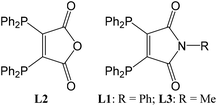
The bidentate phosphine 2,3-bis(diphenylphosphino)maleic anhydride (L2)1,2 and its derivatives3–5 (Fig. 1) represent a class of ligands with low redox potentials. These potential differ depending on the heteroatom in the five-membered ring (L1: −1.37 V, L2 −1.17 V). As a result of this property some of their transition metal complexes show an electron transfer from the metal ion to low lying, unoccupied acceptor states of the ligands; e.g. [(L2)Co(CO)3]6 and [(L3)Mn(CO)4].7 Assuming that cobalt and manganese would have the formal oxidation state 0 these compounds have 19 valence electrons (VE) located at the metal atoms. Indeed as a consequence of the redox properties of the phosphine ligands one electron is transferred from the metal atom onto L2 or L3, respectively, leading to cobalt and manganese in oxidation state +I (18 VE) with the charge balanced by the resulting L2− or L3− radical anions.Reactions of [Ni(CO)4] or [M(PPh3)4] (M = Ni, Pd, Pt) with two equivalents of 2,3-bis(diphenylphosphino)-N-methyl-maleimide (L3) lead to complexes with the composition [M(L3)2].8 For M = Ni the metal atom is tetrahedrally coordinated and this compound is diamagnetic. Accordingly nickel has the oxidation state 0 and both ligands L3 are neutral. In case of palladium and platinum paramagnetic compounds are formed showing square-planar coordination typical for Pd2+ and Pt2+ ions (d8 configuration). Obviously two electrons of the metal atoms were transferred onto the two ligands. In this context these complexes can be described as [M2+(L3−)2]. Similar electron transfer processes have also been described for various complexes containing so-called non-innocent ligands.9–13 Examples for these ligands are indigo,14 2,2-azobispyridine,15 iminoquinones,16,17 phenanthroline,18o-iminosemiquinones19,20 and o-iminobenzosemiquinonato.21,22
Another characteristic of this class of ligands is their tendency of undergoing various substitution and addition reactions in the coordination sphere of transition metals.23–28
In this article we report on the coordination behavior of L1 with coinage metal ions and – in analogy to previous studies8 – also palladium. Some of the new compounds were also investigated with respect to their magnetic properties and modeled by quantum chemical methods.
Results and discussion
Reactions of copper(I) acetate or silver cyclohexylthiolate with bis(diphenylphosphino)-N-phenyl-maleimide (L1) in boiling toluene lead to the formation of neutral mononuclear complex [M(L1L1′)] (M = Cu: 1; Ag: 7). These unexpected results can be explained by redox processes taking place at high temperatures: In case of 1 the initial copper(I) acetate is partly oxidized to copper(II) acetate whereas part of L1 is reduced. The driving force for the formation of 7 might be the oxidation of the cyclohexylthiolate anions to dicyclohexyldisulfide.An analogous gold compound could not be synthesized yet. The two compounds 1 and 7 show similar molecular structures (Fig. 2) where one metal atom is surrounded by the four phosphorus atoms of two ligand molecules in a distorted tetrahedral coordination sphere.
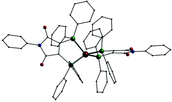 | ||
| Fig. 2 Molecular structure of 1 in solid state; Cu: copper, P: green O: red, N: blue, C: black, H atoms omitted. | ||
As stable compounds with copper or silver in oxidation state 0 have not been confirmed yet (and most probably do not exist),‡ we can surely assume that the metal atoms in 1 and 7 are in oxidation state +I. This indicates that one of the ligands has been reduced to the radical mono-anion L1′, which could be described by the resonance formulae shown in Fig. 3.
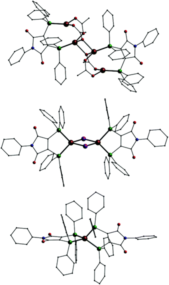
For comparison several more copper, silver and also gold complexes with L1 were synthesized, in which the ligand remains in its neutral state. With copper(I) acetate the tetranuclear compound [(CuOAc)4(L1)2] (2, Fig. 4, top) is formed. This compound consist of two {Cu2(OAc)2L1} subunits which dimerize by additional coordination via one of the oxygen atoms of one acetate of each subunit. Copper(I) halides yield the binuclear complexes [Cu2X2(L1)2] (X = Br−: 3; X = I−: 3, Fig. 4, middle) with a Cu2X2 four-membered ring and each L1 ligand chelating one copper ion. In case of copper(II) sulphate a mononuclear dicationic complex [CuII(L1)2](SO4) (5, Fig. 4, bottom) is formed where the [CuII(L1)2]2+ dication consists of a copper(II) ion coordinated by two neutral L1 ligands very similar to the structure of the neutral compound 1.
Additionally we performed a reaction analogous to the formation of 1 offering a 1![[thin space (1/6-em)]](https://www.rsc.org/images/entities/char_2009.gif) :
:![[thin space (1/6-em)]](https://www.rsc.org/images/entities/char_2009.gif) 1 mixture of the ligands L1 and 2,3-bis(diphenylphosphino)maleic anhydride (L2) where we could isolate a neutral mononuclear complex [Cu(L1L2′)] (6, Fig. 5). As in 1 this compound shows a copper atom which is coordinated by the four phosphorus atoms of the two ligands in a highly distorted tetrahedral arrangement.
1 mixture of the ligands L1 and 2,3-bis(diphenylphosphino)maleic anhydride (L2) where we could isolate a neutral mononuclear complex [Cu(L1L2′)] (6, Fig. 5). As in 1 this compound shows a copper atom which is coordinated by the four phosphorus atoms of the two ligands in a highly distorted tetrahedral arrangement.
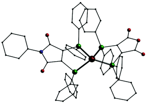 | ||
| Fig. 5 Molecular structure of [Cu(L1L2′)] (6); Cu: copper, P: green O: red, N: blue, C: black, I: violet, H atoms omitted. | ||
Using silver nitrate the reaction with pure L1 yields another cationic mononuclear complex, [Ag(L1)2]NO3 (8). Analogous complexes could also be synthesised from gold(I) sources: [Au(L1)2]X (X = Cl−: 9; X = PF6−: 10, Fig. 6). In these three compounds the cations once more consist of a metal(I) ion tetrahedrally coordinated by the phosphorus atom of two L1 ligands. Just recently a digold complex [(AuCl)2L1] was published, where the two gold(I) ions show the typical linear coordination.29
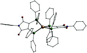 | ||
| Fig. 6 Molecular structure of the monocation [Au(L1)2]+ in 10; Au: gold, P: green O: red, N: blue, C: black, H atoms omitted. | ||
In addition we also investigated the coordination behavior of palladium with L1. Starting from the palladium(0) compound [Pd(Ph3)4] the neutral mononuclear complex [Pd(L1′)2] (11, Fig. 7, top) is formed. An analogous species (A) has been described in the past using (Ph2P)2(C4O2N)Me (L3) as ligand.7 In 11 the palladium atom is surrounded by the four phosphorus atoms in a square planar coordination sphere typical for palladium in oxidation state +II. This means that in 11 the two ligands are present in their reduced anionic form L1′. Once more we synthesized two compounds for comparison. Even with an excess of L1 the reaction of [PdCl2(PPh3)2] only leads to an substitution of the PPh3 ligands resulting in [PdCl2(L1)] (12, Fig. 7, middle). In the presence of KPF6 the mononuclear complex [Pd(L1)2](PF6)2 (13, Fig. 7, bottom) is formed. Also 12 and 13 show the typical square planar coordination of palladium(II) and once more the dication in 13 is very similar to the neutral compound 11.
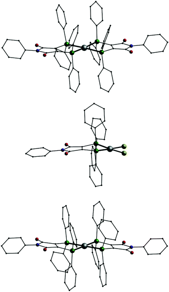 | ||
| Fig. 7 Molecular structures of [Pd(L1′)2] (11, top), [PdCl2(L1)] (12, middle) and the dication [Pd(L1)2]2+ in 13 (bottom); Pd: grey, P: green, Cl: yellow, O: red, N: blue, C: black, H atoms omitted. | ||
The free ligand L1 as well as all metal complexes 1–13 could be isolated as crystalline materials and their structures were determined by single crystal X-ray diffraction. In some cases the compounds crystallize in different packings mainly because of different amounts of incorporated solvent molecules. Compound 1 crystallizes in one reaction batch in two packing variations once in the orthorhombic space group P212121 with the composition 1·2toluene (1a) and secondly in the triclinic space group P![[1 with combining macron]](https://www.rsc.org/images/entities/char_0031_0304.gif) as 1·toluene (1b). Also for 2 two different kinds of crystals are formed: monoclinic crystals in space group P21 having the composition 2·DCM·½cyclohexane (2a, DCM = dichloromethane) and crystals in the triclinic space group P1 as 2·2DCM (2b). Furthermore for 7 a monoclinic solvent-free version in space group C2/c (7a) and a triclinic packing in space group P1 with one additional toluene molecule (7b, with three molecules in the asymmetric unit) could be isolated. Species 9 can be crystallized in a triclinic version in P
as 1·toluene (1b). Also for 2 two different kinds of crystals are formed: monoclinic crystals in space group P21 having the composition 2·DCM·½cyclohexane (2a, DCM = dichloromethane) and crystals in the triclinic space group P1 as 2·2DCM (2b). Furthermore for 7 a monoclinic solvent-free version in space group C2/c (7a) and a triclinic packing in space group P1 with one additional toluene molecule (7b, with three molecules in the asymmetric unit) could be isolated. Species 9 can be crystallized in a triclinic version in P![[1 with combining macron]](https://www.rsc.org/images/entities/char_0031_0304.gif) as 9·2toluene (9a) and monoclinic in C2/c as 9·3DCM (9b). Compound 10 always crystallizes from one reaction batch in two modifications: triclinic in P
as 9·2toluene (9a) and monoclinic in C2/c as 9·3DCM (9b). Compound 10 always crystallizes from one reaction batch in two modifications: triclinic in P![[1 with combining macron]](https://www.rsc.org/images/entities/char_0031_0304.gif) (10a) and monoclinic in P21/n (10b) both having the same composition 10·2½DCM. Also for 11 two different kinds of crystals are yielded, one in the monoclinic space group C2/c without additional solvent molecules (11a) the other one with one additional molecule of DCM in the space group Cc (11b). For 12 even three kinds of crystals were found, which grow simultaneously from one reaction batch: a trigonal form in space group R3 (12a), a monoclinic one in P21/c (12b) and a triclinic form in P
(10a) and monoclinic in P21/n (10b) both having the same composition 10·2½DCM. Also for 11 two different kinds of crystals are yielded, one in the monoclinic space group C2/c without additional solvent molecules (11a) the other one with one additional molecule of DCM in the space group Cc (11b). For 12 even three kinds of crystals were found, which grow simultaneously from one reaction batch: a trigonal form in space group R3 (12a), a monoclinic one in P21/c (12b) and a triclinic form in P![[1 with combining macron]](https://www.rsc.org/images/entities/char_0031_0304.gif) (12c). Finally also 13 crystalizes as two different solvent adducts: 13·2acetone (13a) and 13·3DCM (13b). Detailed crystallographic and refinement data of L1 and 1–13 are given in the electronic supplement in Table S1.†
(12c). Finally also 13 crystalizes as two different solvent adducts: 13·2acetone (13a) and 13·3DCM (13b). Detailed crystallographic and refinement data of L1 and 1–13 are given in the electronic supplement in Table S1.†
One hint, that ligand L1 got reduced in some reactions, are the bond lengths in the maleic imid part. Selected bond lengths of L1 and 1–13 according to Fig. 8 are summarized in Table 1.
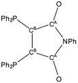 | ||
| Fig. 8 Scheme of L1 showing the atom labelling with respect to Table 1. | ||
| Comp. | CB–CB | CB–CA | CA–O | CA–N | CB–P |
|---|---|---|---|---|---|
| L1 | 134.8(2) | 150.5(2), 151.3(2) | 120.2(2), 120.3(2) | 140.0(2), 140.1(2) | 182.0(2), 183.3(2) |
| 1a | 133.4(8), 139.9(9) | 144.7(9), 145.4(9) , 150.1(9), 150.6(9) | 120.1(8), 120.6(8), 122.2(8), 122.8(8) | 140.4(8), 141.7(8), 142.2(8), 142.3(8) | 177.4(7), 178.0(6) , 183.1(6), 183.3(7) |
| 1b | 136.6(5), 138.2(4) | 146.4(4), 146.5(5), 147.2(4), 149.0(5) | 121.3(4), 121.3(4), 122.0(4), 122.1(4) | 140.6(4), 140.7(5), 140.9(4), 141.5(4) | 180.2(3), 180.3(3), 180.5(3), 180.7(3) |
| 2a | 134.2(2), 136.8(7) | 149.3(9), 150.1(9), 151.3(8), 153.8(9) | 119.2(6), 120.1(6), 120.2(7), 121.5(5) | 138.5(7), 139.0(7), 139.0(7), 140.6(7) | 181.7(6), 182.8(6), 182.9(6), 183.0(6) |
| 2b | 133.8(9), 134.5(9) | 150.6(11), 151.1(11), 151.9(12), 152.6(11) | 118.2(9), 120.3(9), 120.5(8), 121.1(8) | 138.3(9), 139.9(8), 140.3(11), 140.6(11), | 182.4(7), 182.9(8), 184.5(8), 184.7(8) |
| 3 | 133.8(8) | 151.2(7), 152.2(6) | 119.1(8), 119.6(7) | 139.3(8), 140.9(7) | 181.2(5), 183.5(5) |
| 4 | 133.7(5) | 150.7(4), 151.1(4) | 119.9(4), 120.2(4) | 140.0(4), 140.3(4) | 182.2(3), 182.9(3) |
| 5 | 133.2(6), 134.7(6) | 150.3(8), 150.8(7), 150.9(6), 150.9(6) | 119.7(5), 120.0(6), 120.2(6), 120.4(7) | 139.5(5), 139.9(6), 140.2(7), 140.6(7) | 181.4(4), 182.3(5), 182.5(5), 182.7(4) |
| 6 L1 | 133.4(5), 133.5(5), 134.1(6) | 150.5(6), 151.3(5), 151.3(6), 151.7(5), 152.3(7), 153.1(5) | 119.2(6), 119.5(5), 119.8(5), 119.9(6), 120.3(6), 120.8(5), | 138.2(7), 138.5(6), 139.3(5), 140.6(4), 140.7(5), 140.7(6) | 180.8(4), 181.7(5), 182.3(3), 182.5(4), 182.6(4), 182.7(4) |
| L2′ | 139.9(5), 140.9(6), 141.4(7) | 141.8(7), 142.1(5), 143.1(5), 143.3(5), 144.7(5), 144.9(7) | 120.7(5), 120.3(6), 121.8(5), 121.8(7), 121.9(7), 122.4(5) | 140.2(5), 140.5(5), 140.7(5), 141.0(6), 141.1(7), 141.4(5) | 177.3(5), 178.3(4), 178.6(4), 178.8(4), 178.8(4), 179.1(5) |
| 7a | 137.5(6) | 146.6(7), 147.4(6) | 121.5(6), 122.0(6) | 140.8(5), 142.2(6) | 180.0(5), 180.5(4) |
| 7b | 132.9(10), 133.0(10), 133.5(10), 139.9(14), 142.1(13), 142.3(14) | 141.7(11), 143.1(12), 144.0(13), 144.8(10), 144.9(11), 145.2(15), 150.2(13), 150.7(12), 151.3(13), 152.7(11), 153.8(13), 154.2(13) | 117.9(9), 118.5(11), 119.5(11), 119.8(9), 120.2(9), 120.9(10), 121.9(11), 122.1(10), 122.8(14), 123.9(10), 124.2(12), 124.6(12) | 138.8(10), 138.9(10), 139.0(19), 139.1(11), 139.5(11), 140.4(10), 140.5(10), 141.7(11), 141.7(12), 142.0(12), 142.5(12), 142.7(12) | 176.5(9), 177.3(8), 178.1(8), 178.1(10), 178.4(9), 178.4(10) , 181.5(9), 181.9(9), 182.3(9), 182.8(8), 182.9(9), 182.9(10) |
| 8 | 131.8(12), 134.7(13) | 150.5(13), 150.6(14), 151.1(15), 152.0(13) | 119.4(12), 119.6(11), 119.8(10), 120.3(11) | 139.1(11), 139.1(11), 139.6(12), 139.8(11) | 181.8(10), 182.8(10), 184.1(10), 184.1(10) |
| 9a | 134.5(12), 135.7(15) | 149.5(14), 150.4(14), 151.8(14),151.9(15) | 119.7(14), 120.1(10), 120.5(13), 120.7(11) | 139.9(12), 140.5(14), 140.9(15), 141.2(12) | 180.2(12), 180.4(10), 180.6(10), 182.0(9) |
| 9b | 132.5(9), 133.5(13) | 150.7(10), 150.9(13), 151.5(19), 151.4(11) | 118.2(9), 118.8(12), 120.0(10), 121.3(8) | 136.4(9), 138.5(12), 141.7(9), 142.2(9) | 180.5(7), 182.4(8), 182.7(7), 183.0(10) |
| 10a | 131.5(18), 138.8(17) | 148.7(16), 149.9(16), 151.1(14), 153.2(14) | 118.8(16), 119.2(15), 124.8(15), 128.6(17) | 136.2(18), 136.3(15), 138.5(16), 144.1(19) | 177.4(12), 181.1(10), 181.4(11), 182.9(13) |
| 10b | 132.7(12), 132.8(11) | 150.4(9), 150.5(11), 152.8(8), 153.2(9) | 117.6(10), 119.(9), 120.9(10), 121.0(10) | 139.8(9), 141.3(10), 141.3(10), 141.8(10) | 181.0(7), 181.6(8), 181.9(6), 183.0(6) |
| 11a | 141.8(5) | 143.2(7), 143.9(4) | 122.1(3), 122.3(5) | 143.4(6), 147.1(4) | 175.9(3), 177.0(5) |
| 11b | 139.6(13), 141.1(10) | 143.3(11), 143.4(11), 144.2(12), 144.5(12) | 122.2(10), 122.8(11), 123.3(10), 123.4(10) | 141.8(11), 141.8(11), 142.0(10), 143.0(10) | 175.4(7), 175.6(9), 176.1(9), 176.2(9) |
| 12a | 135.0(18) | 149.0(14), 151.6(12) | 118.4(14), 121.8(19) | 137.9(17), 140(16) | 179.6(10), 181.2(9) |
| 12b | 132.8(3), 132.8(3), 132.9(3), 133.0(3) | 149.7(3), 149.7(3), 149.8(3), 150.2(3), 150.2(3), 150.3(3), 150.6(3), 151.3(3) | 119.3(3), 119.4(3), 119.8(3), 119.9(3), 120.3(3), 120.4(3), 120.5(3), 120.7(3) | 139.5(3), 139.8(3), 140.0(3), 140.1(3), 140.6(3), 141.3(3), 141.7(3), 141.7(3) | 181.6(2), 181.7(2), 181.8(2), 181.9(2), 181.9(2), 182.0(2), 182.1(2), 182.3(2) |
| 12c | 132.0(13), 135.3(10) | 149.6(14), 150.1(14), 150.5(12), 151.7(15) | 119.6(10), 119.7(9), 119.7(9), 121.6 (12) | 138.3(11), 141.2(13), 141.4(10), 142.3(11) | 181.0(10), 181.2(8), 181.7(10), 183.4(11) |
| 13a | 132.9(5) | 150.1(4), 150.9(4) | 120.0(4), 120.3(5) | 139.1(4), 139.1(5) | 180.4(3), 180.5(3) |
| 13b | 132.8(4) | 150.9(4), 151.0(4) | 119.7(3), 119.9(3) | 139.5(4), 139.7(3) | 180.6(3), 181.0(3) |
As highlighted by bold italic numbers in Table 1 in some of these compounds the bond lengths of the ligands differ significantly from those found in the free ligand. In agreement with the resonance formulae shown in Fig. 3 the CB–CB bonds are longer, the CB–CA bonds are shorter and the CA–O bonds are longer compared to those in L1. Also the bonds CB–P (shortened) and CA–N (elongated) undergo changes in their lengths. Looking at the data for 1a and 1b the bond lengths suggest that in 1a the complexes [Cu(L1L1′)] (1) are ordered in the packing with defined positions for L1 and L1′. In contrast the bond lengths in 1b are between those of pure L1 and L1′ indicating that the ligands are disordered while one can still assume that each complex should be neutral with composition [Cu(L1L1′)]. The same phenomena is found for 7a and 7b, both containing the neutral complex [Ag(L1L1′)]. For 7b the two ligands have significantly different bond lengths indicating an ordered packing with precise positions for L1 and L1′. On the other hand in 7a the [Ag(L1L1′)] complex is located on a 2-fold axis (the refined asymmetric unit consists of half a molecule) and the bond lengths in the ligand are once more an average between L1 and L1′. In case of the palladium complexes in 11a and 11b the distances clearly show that both ligands have been reduced and 11 should be formulated as a palladium(II) dication coordinated by two anionic L1′ ligands.
Compound 6 crystallizes with three molecules in the asymmetric unit. In case of this mixed complex where two different ligands are present the bond lengths indicate that L1 is present in its neutral form whereas L2 has been reduced to the analogous anion L2′.
For all other complexes – the copper compounds 2–5, the silver species 8, the gold complexes 9 and 10![[thin space (1/6-em)]](https://www.rsc.org/images/entities/char_2009.gif) § as well as the palladium compounds 12 and 13 – the bond lengths indicate that the ligands are present in their original non-charged state and also the oxidation states of the metal ions did not change. This is also in agreement with the anions which are present in these compounds. On the other hand no counterions were found in 1, 7 and 11 during the refinement of the X-ray data leading to the statement that these complexes must be neutral.
§ as well as the palladium compounds 12 and 13 – the bond lengths indicate that the ligands are present in their original non-charged state and also the oxidation states of the metal ions did not change. This is also in agreement with the anions which are present in these compounds. On the other hand no counterions were found in 1, 7 and 11 during the refinement of the X-ray data leading to the statement that these complexes must be neutral.
Another method to verify the thesis that in some cases L1 has been reduced is to look at the significant C–O vibrations in the IR spectra. The wavenumbers of the C–O vibration bands in IR spectra of L1, L2 and 1–13 are summarized in Table 2.
| Comp. | Wavenumber/cm−1 |
|---|---|
| L1 | 1767, 1711 |
| L2 | 1762, 1716 |
| 1 | 1770, 1717, 1664, 1641, 1610 |
| 2 | 1767, 1713 |
| 3 | 1769, 1716 |
| 4 | 1769, 1716 |
| 5 | 1775, 1719 |
| 6 | 1718, 1649, 1602 |
| 7 | 1766, 1712, 1658, 1640, 1607 |
| 8 | 1773, 1716 |
| 9 | 1773, 1716 |
| 10 | 1775, 1719 |
| 11 | 1716, 1671, 1620 |
| 12 | 1774, 1719 |
| 13 | 1777, 1725 |
The pure ligand L1 shows one strong signal at 1711 cm−1 and a weak at 1767 cm−1. For those compounds, where we assume the presence of the anionic ligand L1′, i.e.1, 7, and 11, additional bands between 1670 cm−1 and 1600 cm−1 are present whereas the other complexes show only the strong band between 1713 cm−1 and 1725 cm−1 and the weak one close to 1767 cm−1. For the mixed species 6, where we should also have one anionic ligand, three vibration signals are detected.
As the pure ligand L1 is intensively orange in colour and L2 is yellow, all compounds 1–13 are also coloured. The colours of L1, L2 and 1–13 are listed in Table 3; absorption spectra of solid samples of these compounds in the UV-VIS-NIR range are shown in the supplement (Fig. S1–S13†).
| Comp. | Colour |
|---|---|
| L1 | Orange |
| L2 | Yellow |
| 1 | Dark reddish orange |
| 2 | Bluish violet |
| 3 | Brownish blue |
| 4 | Bluish grey |
| 5 | Brownish red |
| 6 | Dark orange |
| 7 | Dark red |
| 8 | Orange |
| 9 | Red |
| 10 | Bluish violet |
| 11 | Dark red to brown |
| 12 | Yellow |
| 13 | Yellow |
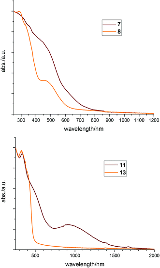
Especially compounds 1, 6, 7 and 11, which we suppose having ligands with unpaired electrons, are intensively dark in colour, a phenomenon typical for radicals. These effects can best be seen by comparing 7 with 8 or 11 with 13, respectively. Looking at the structures of these pairs, the geometry and binding parameters of the complexes are very similar. In 7 and 8 there is one silver atom tetrahedrally surrounded by the four phosphorus atoms of the two ligands. Compound 7 – with the radical ligand L1′ – is dark red, whereas 8 – with two neutral ligands L1 and the charge being compensated by a nitrate anion – is bright orange. The same differences can be observed in the two palladium complexes, which both show a square planar coordination of the metal: the neutral compound 11 has a dark red to brown colour whereas the ionic compound 13 is yellow. These effects can also be seen in the solid state UV-VIS absorption spectra (Fig. 9) where the neutral compounds have significant absorption at higher wavelengths compared to the ionic ones. Looking at the spectra of 7 and 8 the absorption of 7 is red shifted (Fig. 9, top). Comparing 11 with 13, (Fig. 9, bottom) the spectrum of compound 11 shows a broad absorption signal in the near IR region cantered at 930 nm.
Magnetic properties
The static magnetic behavior of complex [Cu(L1L1′)] (1) was studied between 2 and 300 K in a field of 1000 Oe (Fig. 10). At 2 K the value of χT (0.30 cm3 mol−1 K) is below the one expected for a spin state of S = 1/2 with one unpaired electron localized on one of the ligands. With increasing temperature χT displays a small linear increase. In agreement with these observations the data could be fitted by the PHI program30 (eqn (S1) in ESI†) with the parameters S = 1/2, g = 1.79 and a TIP of 4.4 × 10⁻⁴ cm3 mol−1. The simultaneous fit of the magnetization data (Fig. S14 in ESI†) taken at 2 K, 3 K, 4 K, 6 K, 10 K and 25 K display some slight deviations especially for the data at lower temperature and higher fields.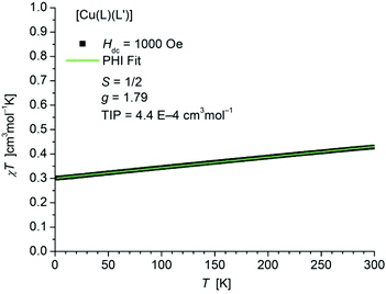 | ||
| Fig. 10 Temperature dependence of χT of [Cu(L1L1′)] (1). The solid green line represents the result of the simultaneous fitting with the temperature dependent magnetization (Fig. S14 in ESI†) according to a Spin Hamiltonian (eqn (S1) in ESI†) by the PHI program. | ||
The static magnetic behavior of complex [Ag(L1L1′)] (7) was studied between 2 and 150 K in a field of 5000 Oe (Fig. 11). At 2 K the value of χT (0.36 cm3 mol−1 K) is close to the one expected for a spin state of S = 1/2 with one unpaired electron localized on one of the ligands. With increasing temperature χT displays a small linear increase. In agreement with these observations the data could be fitted by the PHI program30 (eqn (S1) in ESI†) with the parameters S = 1/2, g = 1.953 and a TIP of 4.27 × 10⁻⁴ cm3 mol−1. Above 150 K the paramagnetic signal of the sample continuously changes to a diamagnetic one due to the significant diamagnetic contribution of the two ligands (χdia = −910 10−6 cm3 mol−1) which causes centering problems and makes an evaluation of the data unreliable.
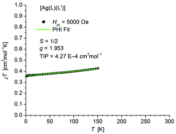 | ||
| Fig. 11 Temperature dependence of χT of [Ag(L1L1′)] (7). The solid green line represents the result of the fitting according to a Spin Hamiltonian (eqn (S1) in ESI†) by the PHI program. | ||
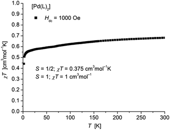
The static magnetic behavior of complex [Pd(L1′)2] (11) was studied between 2 and 300 K in a field of 1000 Oe (Fig. 12). At room temperature the value of χT (0.68 cm3 mol−1 K) is distinctly lower than the one expected for a spin state of S = 1 with two non-interacting unpaired electrons localized on each of the ligands. With decreasing temperature χT decreases down to a value of 0.44 cm3 mol−1 K at 2 K indicative for an antiferromagnetic exchange interaction. In accordance, magnetization measurements at 2 K (Fig. S15 in ESI†) do not show saturation up to a field of 7 T with a maximum value of MH = 1.43NAμB which is also well below a theoretical MS = 2 for a spin state of S = 1.
Quantum chemical calculations
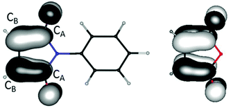
For two of the complexes (1a and 7b) the two ligands of identical composition exhibit different structure parameters. One is apparently reduced while the other is not. This is unexpected, at least if considering a single molecule in the gas phase. One might rather have expected a partial reduction of both ligands, resulting from maximum delocalization of the unpaired electron. For clarification and quantification of the reasons for this symmetry breaking, quantum chemical calculations31 were carried out with density functional techniques (B3-LYP functional,32 polarized split-valence basis sets33). For modelling the electrostatic influence of neighbored molecules in the crystal the conductor-like screening model (COSMO)34 was used in some of the calculations; if applied it is always explicitly noted.We start with considering the free ligands L1 and L2. Their LUMOs are shown in Fig. 13. They are anti-bonding with respect to the CB–CB bond and bonding with respect to the CB–CA bonds. Consequently, the latter are shortened upon reduction while the former are elongated. This effect is also found in the experimental solid state structures for 1a, 6, 7b and 11 (see Table 1). The changes amount to ca. 6 pm in both cases, see also Fig. 13. Thus, for instance the CB–CB distances are convenient measures for the oxidation state both in experimentally obtained and in calculated structures.
Studies were continued with optimizations of structure parameters of [Cu(L1L2′)] (6), [Cu(L1L1′)] (1), [Ag(L1L1′)] (7), [Ag(L1L1)]+ (cation in 8), [Pd(L1′)2] (11) and [Pd(L1)2]2+ (dication in 13). We always started from the experimental structure and used COSMO in all cases. The resulting CB–CB and CB–CA distances are listed in Table 4 together with the number of unpaired electrons on both ligands, as resulting from a Mulliken population analysis. The shorter type of CB–CB distances amounts to ca. 135 pm, the longer type to ca. 142 pm, very similar to the measured data, 132 to 135 pm and 140 to 142 pm, and also to that for the free ligands in the respective oxidation state, see Fig. 13. In particular, the asymmetric shapes of 6, 1a and 7b are preserved. The numbers of unpaired electrons at the ligands are well correlated to the CB–CB and CB–CA distances: the unpaired electron always fully resides on the ligand with the longer CB–CB distance and the shorter CB–CA distances.
| d(CB–CB)/pm | d(CA–CB)/pm | Unpaired electr. | ||||
|---|---|---|---|---|---|---|
| Left | Right | Left | Right | Left | Right | |
| [Cu(L1L2′)] (6) | 135.2 | 141.9 | 151.3; 151.6 | 144.1; 144.2 | 0 | 0.96 |
| [Cu(L1L1′)] (1) | 135.3 | 142.1 | 151.5; 151.7 | 145.1; 145.3 | 0 | 0.97 |
| [Ag(L1L1′)] (7) | 135.2 | 142.0 | 151.6; 151.7 | 145.3; 145.4 | 0 | 0.95 |
| [Ag(L1L1)]+ in 8 | 135.2 | 135.1 | 151.7; 151.8 | 151.6; 151.7 | 0 | 0 |
| [Pd(L1′)2] (11) | 140.6 | 140.7 | 146.4; 146.4 | 146.3; 146.4 | 0.92 | 0.94 |
| [Pd(L1)2]2+ in 13 | 135.1 | 135.2 | 151.5; 151.9 | 151.6; 151.9 | 0 | 0 |
The asymmetric form of [Cu(L1L2′)] (6) – with L2′ being reduced and incorporating the unpaired electron – is expected due to the higher absolute value of the electron affinity of L2, see Fig. 13. For [Cu(L1L1′)] (1) and [Ag(L1L1′)] (7) in contrast, the preservation of the asymmetric structure after its optimization (with COSMO) is a bit surprising. However, as exemplarily calculated for 1, the energetic preference of the asymmetric structure (A as found in 1a) over a symmetric structure (S in 1b) amounts to 15 kJ mol−1; S was obtained by interpolation between the two variants of A (CuL1L1′ and CuL1′L1). We discuss this preference by comparing the total energy and the contribution from the interaction with the neighbored molecules in the crystal within COSMO, Eint, for three cases: structures A, and S, and a minimally distorted symmetric structure S′ (derived from S), for which the two CB–CB distances differ by only 0.5 pm. For S, the singly occupied HOMO is the positive linear combination of the LUMO of L1 at the right and L1 at the left hand side of the molecule. The unpaired electron thus is equally distributed to the two ligands; for S, Eint amounts to 122 kJ mol−1. For S′ in contrast, the unpaired electron is located solely at the ligand with the slightly (0.5 pm) longer CB–CB distance. The resulting polarity of the molecule is energetically favorable for the interaction with the neighbor molecules: Eint increases by 25 kJ mol−1. However, localization at only one of the ligands is unfavorable for the energy of the molecule itself. The total energy, which is the sum of the energy of the molecule and Eint, is worse for S′ than for S by 4 kJ mol−1. Thus, the energy gain by Eint obviously is (over)compensated by an energy loss due to the higher localization of the unpaired electron. Relaxation of the geometric structure of S′ finally yields the antisymmetric structure A. This comes along with a gain in energy by 19 kJ mol−1 in the total energy. This gain is solely due to structure relaxation; the interaction energy with the neighbored molecules is almost constant (Eint changes by only 0.1 kJ mol−1) and yields the overall preference of 15 kJ mol−1 of A over S. In contrast, the analogous calculation with the environment interaction being neglected (by switching off COSMO) yields a slight preference of 3.5 kJ mol−1 for the symmetric species; moreover, in this case A no longer is a minimum but converges to S when performing a structure optimization. The observed asymmetry thus is not a simple effect of crystal packing, but the result of a fragile balance of energy needed for localizing the electron at one side and energy gained by interaction with the neighbor molecules in the crystal. If the latter plus the energy gain by subsequent structure relaxation effects are larger than the former, the molecule is asymmetric despite two identical ligands.
Conclusions
Using bis(diphenylphosphino)-N-phenyl-maleimide (L1) in coordination chemistry of coinage metals or palladium, respectively, one can isolate neutral mononuclear complexes were the ligand is reduced to form the anionic monoradical L1′: [Cu(L1L1′)] (1), [Ag(L1L1′)] (7) and [Pd(L1′)2] (11). These compounds and a series of comparable complexes in which the ligand did not accept an electron were characterized by single crystal X-ray analysis. The nature of the reduced ligand in 1, 7 and 11 could be verified by several indicators: the bond lengths in L1 and L1′ show significant differences, the CO vibration signals in IR spectra are shifted and also magnetic measurements proved the existence of unpaired electrons. Also quantum chemical calculations show the presence of unpaired electrons localized on the ligands in compounds 1, 6, 7 and 11. Furthermore calculations for 1 show a small but significant preference for the asymmetric arrangement, i.e. localization of the electron on one side of the complex, in contrast to symmetric arrangement with the electron being delocalized on both ligands.Conflicts of interest
There are no conflicts to declare.Acknowledgements
The authors are grateful to Mr Sven Stahl and Mrs Milena Staub for their assistance in the laboratory. This work was supported by the 111 project (90002-18011002) and the National Natural Science Foundation of China (21720102007).Notes and references
- D. Fenske and H. J. Becher, Chem. Ber., 1974, 107, 117–122 CrossRef CAS.
- H. J. Becher, W. Bensmann and D. Fenske, Chem. Ber., 1977, 110, 315–321 CrossRef CAS.
- D. Fenske and H. J. Becher, Chem. Ber., 1975, 108, 2115–2123 CrossRef CAS.
- D. Fenske and A. Christidis, Angew. Chem., 1981, 93, 113–115 ( Angew. Chem. Int. Ed. , 1981 , 20 , 129–131 ) CrossRef CAS.
- H. J. Becher, D. Fenske and M. Heymann, Z. Anorg. Allg. Chem., 1981, 475, 27–34 CrossRef CAS.
- D. Fenske, Angew. Chem., 1976, 88, 415 ( Angew. Chem. Int. Ed. , 1976 , 15 , 381–382 ) CrossRef CAS.
- D. Fenske, Chem. Ber., 1979, 112, 363–375 CrossRef CAS.
- W. Bensmann and D. Fenske, Angew. Chem., 1979, 91, 754–755 ( Angew. Chem. Int. Ed. , 1979 , 18 , 677–678 ) CrossRef CAS.
- W. Kaim and A. Paretzki, Coord. Chem. Rev., 2017, 344, 345–354 CrossRef CAS.
- S. Kuwata and T. Ikariya, Chem. Commun., 2014, 50, 14290–14300 RSC.
- S. Sproules and K. Wieghardt, Coord. Chem. Rev., 2010, 254, 1358–1382 CrossRef CAS.
- A. B. P. Lever, Coord. Chem. Rev., 2010, 254, 1397–1405 CrossRef CAS.
- P. Deplano, L. Pilia, D. Espa, M. L. Mercuri and A. Serpe, Coord. Chem. Rev., 2010, 254, 1434–1447 CrossRef CAS.
- M. Chatterjee, P. Mondal, K. Beyer, A. Paretzki, W. Kaim and G. K. Lahiri, Dalton Trans., 2017, 46, 5091–5102 RSC.
- B. Sarkar, S. Patra, J. Fiedler, R. B. Sunoj, D. Janardanan, G. K. Lahiri and W. Kaim, J. Am. Chem. Soc., 2008, 130, 3532–3542 CrossRef CAS PubMed.
- S. Bhattacharya, P. Gupta, F. Basuli and C. G. Pierpont, Inorg. Chem., 2002, 41, 5810–5816 CrossRef CAS PubMed.
- M. G. Chegerev, A. V. Piskunov, A. A. Starikova, S. P. Kubrin, G. K. Fukin, V. K. Cherkasov and G. A. Abakumov, Eur. J. Inorg. Chem., 2018, 1087–1092 CrossRef CAS.
- M. Wang, T. Weyhermüller and K. Wieghardt, Eur. J. Inorg. Chem., 2015, 3246–3254 CrossRef CAS.
- C. N. Verani, S. Gallert, E. Bill, T. Weyhermüller, K. Wieghardt and P. Chaudhuri, Chem. Commun., 1999, 1747–1748 RSC.
- J. Jacquet, E. Salanouve, M. Orio, H. Vezin, S. Blanchard, E. Derat, M. Desage-El Murr and L. Fensterbank, Chem. Commun., 2014, 50, 10394–10397 RSC.
- P. Chaudhuri, C. N. Verani, E. Bill, E. Bothe, T. Weyhermüller and K. Wieghardt, J. Am. Chem. Soc., 2001, 123, 2213–2223 CrossRef CAS PubMed.
- X. Sun, H. Chun, K. Hildenbrand, E. Bothe, T. Weyhermüller, F. Neese and K. Wieghardt, Inorg. Chem., 2002, 41, 4295–4303 CrossRef CAS PubMed.
- W. Bensmann and D. Fenske, Angew. Chem., 1978, 90, 488–489 ( Angew. Chem. Int. Ed. , 1978 , 17 , 462–463 ) CrossRef CAS.
- K. Ejsmont, W. H. Watson, J. Liu and M. G. Richmond, J. Chem. Crystallogr., 2003, 33, 541–547 CrossRef CAS.
- W. H. Watson, S. G. Bodige, J. Liu and M. G. Richmond, Struct. Chem., 2003, 14, 369–375 CrossRef CAS.
- W. Yu, O. Fuhr and D. Fenske, J. Cluster Sci., 2012, 23, 753–766 CrossRef CAS.
- W. Yu, L. Guggolz, O. Fuhr, D. Fenske and S. Dehnen, Dalton Trans., 2015, 44, 9363–9366 RSC.
- W. Yu, Y. Wang, O. Fuhr, D. Fenske and S. Dehnen, Dalton Trans., 2018, 47, 1032–1035 RSC.
- R. Nyamwihura, L. Yang, V. N. Nesterov and M. G. Richmond, J. Mol. Struct., 2017, 1129, 188–194 CrossRef CAS.
- N. F. Chilton, R. P. Anderson, L. D. Turner, A. Soncini and K. S. Murray, J. Comput. Chem., 2013, 34, 1164–1175 CrossRef CAS PubMed.
- TURBOMOLE V7.2, 2017, a development of University of Karlsruhe and. Forschungszentrum Karlsruhe GmbH, 1989–2007, TURBOMOLE GmbH, since 2007 Search PubMed.
- C. Lee, W. Yang and R. G. Parr, Phys. Rev. B, 1988, 37, 785–789 CrossRef CAS.
- F. Weigend and R. Ahlrichs, Phys. Chem. Chem. Phys., 2005, 7, 3297–3305 RSC.
- A. Klamt and G. Schürmann, J. Chem. Soc., Perkin Trans., 1993, 2, 799–805 RSC.
- G. W. Wattand and J. W. Dawes, J Inorg. Nucl. Chem., 1960, 14, 32–34 CrossRef.
- A. J. Layton, R. S. Nyholm, G. A. Pneumaticakis and M. L. Tobe, Nature, 1967, 214, 1109–1110 CrossRef CAS.
- T. Murugesan, P. R. Sarode, J. Gopalakrishnan and C. N. R. Rao, J. Chem. Soc., Dalton Trans., 1980, 837–839 RSC.
- J. A. Howard, B. Mile, J. R. Morton and K. F. Preston, J. Phys. Chem., 1986, 90, 2027–2029 CrossRef CAS.
- A. J. Layton, R. S. Nyholm, G. A. Pneumaticakis and M. L. Tobe, Nature, 1968, 218, 950 CrossRef CAS.
- F. A. Cotton, G. Wilkinson, C. A. Murillo and M. Bochmann, Advanced Inorganic Chemistry, 6th edn, Wiley, New York, 1999, pp. 854, 1097 Search PubMed.
- A. F. Hollemann, E. Wiberg and N. Wiberg, Anorganische Chemie, Band2, de Gruyter, Berlin, 103th edn, 2017, p. 1693 Search PubMed.
- H. Huber, E. P. Kündig, M. Moskovits and G. A. Ozin, J. Am. Chem. Soc., 1975, 97, 2097–2106 CrossRef CAS.
- M. E. Alikhani and L. Manceron, J. Mol. Spec., 2015, 310, 32–38 CrossRef CAS.
Footnotes |
| † Electronic supplementary information (ESI) available: Experimental details and crystallographic data. CCDC 1847908 (L1), 1847913–1847934 (1a–13b). For ESI and crystallographic data in CIF or other electronic format see DOI: 10.1039/c8dt05003a |
| ‡ In the 1960s and 1980s few reports about copper(0) and silver(0) compounds35–38 were published, but in more recent publications none of these compounds is mentioned any more (in one case even the original authors themselves doubt their previous report39). Standard textbooks of inorganic chemistry also do not note any stable copper(0) or silver(0) compounds.40,41 Instable copper carbonyls have been detected captured in solid argon or neon matrix.42,43 |
| § All X-rayed crystals of 10a and 10b were found to be twinned. For 10a only an uncomplete (87%) low quality data set could be obtained. This might be the reason for the large variations of the bond lengths for this compound compared to all other structures published in this paper. |
| This journal is © The Royal Society of Chemistry 2019 |

