
 Open Access Article
 This Open Access Article is licensed under a Creative Commons Attribution-Non Commercial 3.0 Unported Licence
A high-entropy B4(HfMo2TaTi)C and SiC ceramic composite†
Hanzhu
Zhang
 a,
Daniel
Hedman
a,
Peizhong
Feng
b,
Gang
Han
c and
Farid
Akhtar
*a
a,
Daniel
Hedman
a,
Peizhong
Feng
b,
Gang
Han
c and
Farid
Akhtar
*a
aDivision of Materials Science, Luleå University of Technology, 971 87 Luleå, Sweden. E-mail: farid.akhtar@ltu.se
bSchool of Materials Science and Engineering, China University of Mining and Technology, 221116, Xuzhou, China
cSchool of Materials Science and Engineering, University of Science and Technology Beijing, 100083, Beijing, China
First published on 8th February 2019
Abstract
A multicomponent composite of refractory carbides, B4C, HfC, Mo2C, TaC, TiC and SiC, of rhombohedral, face-centered cubic (FCC) and hexagonal crystal structures is reported to form a single phase B4(HfMo2TaTi)C ceramic with SiC. The independent diffusion of the metal and nonmetal atoms led to a unique hexagonal lattice structure of the B4(HfMo2TaTi)C ceramic with alternating layers of metal atoms and C/B atoms. In addition, the classical differences in the crystal structures and lattice parameters among the utilized carbides were overcome. Electron microscopy, X-ray diffraction and calculations using density functional theory (DFT) confirmed the formation of a single phase B4(HfMo2TaTi)C ceramic with a hexagonal close-packed (HCP) crystal structure. The DFT based crystal structure prediction suggests that the metal atoms of Hf, Mo, Ta and Ti are distributed on the (0001) plane in the HCP lattice, while the carbon/boron atoms form hexagonal 2D grids on the (0002) plane in the HCP unit cell. The nanoindentation of the high-entropy phase showed hardness values of 35 GPa compared to the theoretical hardness value estimated based on the rule of mixtures (23 GPa). The higher hardness was contributed by the solid solution strengthening effect in the multicomponent hexagonal structure. The addition of SiC as the secondary phase in the sintered material tailored the microstructure of the composite and offered oxidation resistance to the high-entropy ceramic composite at high temperatures.
Introduction
Ultrahigh temperature ceramics (UHTCs) like Zr2B,1,2 HfB2![[thin space (1/6-em)]](https://www.rsc.org/images/entities/char_2009.gif) 3 and TaC4,5 with high thermal stability and remarkable mechanical properties, including high hardness, high mechanical strength and good wear resistance, can tolerate extreme working environments involving elevated temperatures and high loadings. These ceramics have been widely studied for high temperature applications in the form of monolithic ceramics and composites.6–8 In terms of UHTC composites, silicon carbide has been incorporated to process UHTCs to tailor the microstructure and enhance the high temperature oxidation resistance.9–13 Inspired by the concept of high-entropy alloys (HEAs), scientific efforts have been devoted to a new branch of UHTCs incorporating high-entropy ceramics (HECs). Developed from multicomponent ceramic compounds such as metallic oxides, nitrides or carbides, HECs show the possibility of forming a single-phase solid solution, in both bulk and film forms.14–16 The single-phase HECs display superior mechanical properties compared to conventional ceramic materials, due to severe lattice distortion and the sluggish diffusion effect, which make them suitable for applications requiring high mechanical performance and phase stability at elevated temperatures.17–19 The first crystalline HECs with a single-phase face-centered cubic (FCC) crystal structure were fabricated from metallic oxides by Rost, C.M. et al. in 2015.20 Later, Joshua Gild et al. sintered high-entropy diboride with a hexagonal close packed (HCP) crystal structure, which showed improved mechanical properties over individual borides.14 Notably, the phase formation rules in HEC systems, i.e., thermodynamics and geometry criteria, are followed while designing HECs. In the recent HEC studies by Rost C.M.,20 Joshua Gilda14 and Elinor Castle,21 the focus was on using one certain ceramic system, either metal oxide, boride or carbide. It is considered that as the starting materials in a HEC system, ceramic compounds (preferably metallic ceramic compounds with only one nonmetallic element) have the least geometrical difference in their lattice structures and can lead to a single-phase solid solution.
3 and TaC4,5 with high thermal stability and remarkable mechanical properties, including high hardness, high mechanical strength and good wear resistance, can tolerate extreme working environments involving elevated temperatures and high loadings. These ceramics have been widely studied for high temperature applications in the form of monolithic ceramics and composites.6–8 In terms of UHTC composites, silicon carbide has been incorporated to process UHTCs to tailor the microstructure and enhance the high temperature oxidation resistance.9–13 Inspired by the concept of high-entropy alloys (HEAs), scientific efforts have been devoted to a new branch of UHTCs incorporating high-entropy ceramics (HECs). Developed from multicomponent ceramic compounds such as metallic oxides, nitrides or carbides, HECs show the possibility of forming a single-phase solid solution, in both bulk and film forms.14–16 The single-phase HECs display superior mechanical properties compared to conventional ceramic materials, due to severe lattice distortion and the sluggish diffusion effect, which make them suitable for applications requiring high mechanical performance and phase stability at elevated temperatures.17–19 The first crystalline HECs with a single-phase face-centered cubic (FCC) crystal structure were fabricated from metallic oxides by Rost, C.M. et al. in 2015.20 Later, Joshua Gild et al. sintered high-entropy diboride with a hexagonal close packed (HCP) crystal structure, which showed improved mechanical properties over individual borides.14 Notably, the phase formation rules in HEC systems, i.e., thermodynamics and geometry criteria, are followed while designing HECs. In the recent HEC studies by Rost C.M.,20 Joshua Gilda14 and Elinor Castle,21 the focus was on using one certain ceramic system, either metal oxide, boride or carbide. It is considered that as the starting materials in a HEC system, ceramic compounds (preferably metallic ceramic compounds with only one nonmetallic element) have the least geometrical difference in their lattice structures and can lead to a single-phase solid solution.
B4C is well known to have a high melting point, high strength and relatively low thermal expansion and conductivity. An HEC composite containing B4C and other UHTCs such as HfC, Mo2C, TaC, TiC and SiC can theoretically benefit by gaining reinforcement effects from all the constituents.22–25 However, HECs combining both boride and carbide systems have not been attempted because of the large differences in their physical and crystallographic properties, including, for example, that the density of HfC is 12.2 g cm−3 while the density of B4C is low as 2.52 g cm−3. Moreover, the aforementioned ceramic system shows vast differences in its crystal structures (FCC, HCP and rhombohedral), which makes the formation of the high-entropy phase from these constituents challenging.
In this research, a new high-entropy ceramic composite containing the UHTC constituents HfC, Mo2C, TaC, TiC, B4C and SiC whiskers (SiCw) was designed and in situ synthesized and consolidated by pulsed current processing (PCP). The single-phase HECs were achieved in an unconventional high-entropy system containing four metal atoms (Hf, Mo, Ta, and Ti) and two nonmetallic atoms (C and B). The high-entropy phase was assessed using electron microscopy and X-ray diffraction (XRD). The distribution of atoms in the HCP high-entropy crystal structure was investigated by experimental XRD and evolutionary crystal structure predictions using density-functional theory (DFT). The nanoindentation hardness, oxidation behaviour and wear resistance properties of the SiC-HEC composite were investigated and showed remarkable improvement of the mechanical properties and oxidation resistance.
Results and discussion
The microstructure of the high-entropy ceramic (HEC) composite in Fig. 1 shows that the PCP sintered HEC composite consists of two phases. According to the corresponding energy-dispersive X-ray spectroscopy (EDS) compositional mapping, the bright phase has a uniform distribution of Hf, Mo, Ta and Ti metal atoms, and the dark phase is rich in Si and C in the composite. The bright high-density phase in the microstructure refers to the high-entropy ceramic B4(HfMo2TaTi)C phase, and the low-density dark phase represents SiC, according to the sensitivity of atomic number by the backscattered electron detector.26 The volume fraction of these phases was estimated to be 3:1 (bright:dark phase) by the “point counting” method (ASTM E562-08).27 It can be seen that the SiC whiskers lost their rod-like shape and coalesced, while the high-entropy phase is displayed as “connected islands” with a grain size of 5–10 μm in the microstructure. A similar microstructure of the composite and the morphology change of the SiCw reinforcement at a high sintering temperature (>1600 °C) have also been observed in other UHTC-SiCw composites.28–30 The addition of SiCw in the ceramic composite inhibited the grain growth of the HEC phase, which can be beneficial for the mechanical properties of the composite by the grain-boundary strengthening mechanism.28,31 The average composition ratio of metal atoms in the HEC phase was investigated by compositional mapping analysis on the high-entropy phase at ten different locations. It was found that the high-entropy solid solution consisted of an equal-atomic ratio of the four metallic elements, which was consistent with the mixing ratio of the starting precursors excluding SiC. As EDS lacks the accuracy for the detection of light elements,32 the presence of B and C in the HEC phase was investigated by wavelength dispersive X-ray spectroscopy (WDS). In Fig. 1b, the WDS spectrum recorded from the high-entropy phase confirms that the HEC phase consists of all four metal elements (Hf, Mo, Ta and Ti) and the nonmetallic elements (C and B). Therefore, we conclude that the precursor carbides (B4C, HfC, Mo2C, TaC and TiC) have formed a single-phase solid solution, and SiCw as the secondary phase is uniformly distributed in the microstructure.
 | ||
| Fig. 1 The microstructure of the PCPed HEC composite shows the presence of two different phases. Both (a) EDS compositional mapping and (b) WDS analysis show that the bright high-entropy ceramic phase contains Hf, Mo, Ta, Ti, C and B. | ||
The X-ray diffraction (XRD) data in Fig. 2a show the phase evolution from precursors with various crystal structures to a single-crystal structure after sintering. The HEC phase exhibits a hexagonal close-packed (HCP) crystal structure, which is confirmed by the selected area diffraction (SAD) pattern taken from the high-entropy phase (Fig. 2b). The lattice parameters of the obtained high-entropy phase were identified from the XRD pattern as a = 0.307 nm and c = 0.330 nm. The lattice planes of the HCP structure identified in Fig. 2a are denoted by considering the primitive hexagonal unit cell. The lattice strain for individual reflection planes of the HCP structure was calculated by the Wilson equation33 included in XRD analysis software Highscore Plus after subtracting Kα2 radiation for the analysis. The current high-entropy ceramic phase shows an average lattice strain of 0.083%, with the highest strain on the (001), (002) and (103) planes, which is lower than the reported lattice strain in a metallic high-entropy system (1–2%).34,35
 | ||
| Fig. 2 The phase identification of the HEC composite. The XRD diffratograms of the high-entropy ceramic composite in (a) show the phase evolution before/after PCP and the calculated lattice strain in the individual lattice planes, the crystal structure was shown in the SAD pattern (b) taken from the high-entropy ceramic phase in the PCPed composite. | ||
Compared with the precursor carbides, it can be seen that HEC has smaller lattice parameters but a similar cell volume (0.02693 nm3) (Table 1). The refractory carbides from Group IV and Group V are well known for the mutual solubility. Among the metallic carbide precursors in this study, the system has the maximum mutual solubility when HfC, TaC or TiC act as the solvent carbide compared to Mo2C being the solvent carbide.36 In addition, Ta has the lowest metal vacancy formation energy in the carbide (3.5 eV) compared with Hf (9.3 eV) and Ti (8.6 eV),21 thereby suggesting that the metal atoms diffuse into the TaC lattice rather than Ta diffusing into other carbide lattices. Another significant fact is that in carbide lattices, the diffusion of metal atoms is independent of that of carbon atoms.21,37 The self-diffusion rate of carbon has been reported to be several orders of magnitude faster than metal atoms, because carbon atoms jump to a tetrahedral hole before they migrate to the carbon vacancy whilst metal atoms only migrate to metal vacancies,38 resulting in a lower activation energy of carbon self-diffusion.39 Therefore, we extrapolated that the whole-phase transformation process toward the HEC phase in the high-temperature ceramic composite includes two important parts. The first stage is the complex rearrangement of atoms with the FCC metal carbide TaC acting as the host lattice and the elements Hf, Ti, Mo, C and B from other constituents migrating as guest atoms through the diffusion process. During the diffusion process, metal atoms and C/B atoms diffuse independently in their own sublattices (metal and nonmetal atoms) and form alternating layers in the lattice. Apart from the complex diffusion process, the host FCC lattice structure also experiences a change in the stacking sequence, resulting in a high-entropy phase with Hf, Mo, Ta, Ti, B and C atoms presented in the HCP lattice. Such a phase transition from an FCC to HCP structure, which is induced by the pressure in the high-entropy system, has been reported.40
| Component | Crystal structure | Niggli-reduced cell volume (nm3) | Lattice parameters a (nm) | Lattice length at the close-packed plane a′ (nm) | δ a′ |
|---|---|---|---|---|---|
| HfC | FCC | 0.02497 | 0.4640 | 0.3281 | 4.84% |
| TaC | FCC | 0.02211 | 0.4442 | 0.3141 | |
| TiC | FCC | 0.02024 | 0.4315 | 0.3060 | |
| Mo2C | Hexagonal | 0.03676 | 0.3000 | 0.3000 | |
| B4C | Rhombohedral | 0.10950 | 0.5600 |
In a traditional high-entropy alloy system, the atomic size difference (δ) between the solute and solvent atoms should be less than 15% in order to form substitutional solid solutions, and the crystal structure of elements is suggested to be the same according to the Hume–Rothery (H–R) rules.41 Because of the existence of two different sublattices (metal and nonmetal atoms) and their independent diffusion behavior in the current carbide system, H–R theory cannot define the phase selection rule. Based on the discussion of the complex diffusion process, the choice of metal atoms is considered to be the essential factor in the formation of high-entropy ceramic solid solution. We have determined the geometric factor δa′ from four metal carbides HfC, Mo2C, TaC and TiC.
Since metal atoms migrate only to the nearest metal vacancy on their original planes, it is suggested that the migration of metal atoms occurs only at the close packed planes of (111) for FCC metal carbides and (0001) for Mo2C (HCP), respectively. Thus, the lattice length a′ was determined based on their close packed planes. Since HfC, TaC and TiC have a rocksalt (NaCl) crystal structure that contains 8 atoms per cell, a′ was calculated based on the reduced primitive cell by eqn (1), while a′ for Mo2C stays the same as its lattice parameter a.
 | (1) |
 | (2) |
Based on the experimentally obtained XRD diffractogram, a theoretical prediction of the HEC crystal structure can be obtained. From the diffraction peaks in Fig. 2a, we determine that the primitive Bravais lattice is hexagonal with lattice parameters of a, b = 0.307 nm and c = 0.330 nm. As the highest intensity peaks correspond to the (001), (101) and (101) lattice planes, the atoms with the highest atomic scattering factor (the metal atoms) were placed at a point in the lattice where these planes intersect. As seen in Fig. 3b, the intersection point of these planes is the origin (0,0,0). With only the metal atoms placed in the lattice (Fig. 3c), a simulated XRD pattern that closely matches the experimental one was obtained. However, it is clear from Fig. 3a that a lattice containing only metal atoms underestimates the intensity of the peak corresponding to the (101) plane.
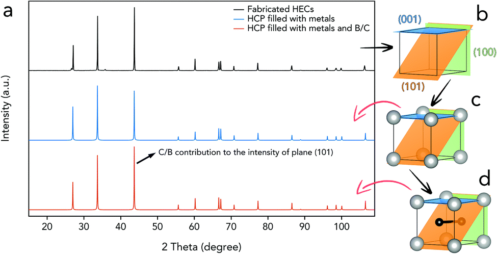 | ||
| Fig. 3 Theoretical lattice structure for the HEC phase derived from the experimental XRD results. (a) The experimental XRD pattern compared with the simulated XRD patterns for the structures shown in (c) and (d). (b) The empty HCP HEC primitive unit cell showing the planes corresponding to the three highest diffraction peaks. (c) The HEC lattice filled with metal atoms (gray) at (0,0,0) where all three planes intersect. (d) The HEC lattice filled with both metal and nonmetal atoms (black) along the (101) plane at positions (1/3,2/3,1/2) and (2/3,1/3,1/2). | ||
The difference in the reflection intensity for plane (101) is due to the absence of carbon/boron in the simulated lattice. This finding implies that the fabricated high-entropy phase contains a carbon/boron hexagonal-shaped 2D grid in the (002) plane of the HCP lattice, which is consistent with the assumption of the independent diffusion of metal and carbon/boron atoms. Thus, we extrapolate that the position of the nonmetal atoms in the lattice must lie on the (101) plane, in order to intensify the peak corresponding to this plane. The placement of the nonmetal atoms is thus determined to be at positions (x,y,z) = (1/3,2/3,1/2) and (2/3,1/3,1/2) in the lattice. With the lattice filled with both metal and nonmetal atoms at the determined positions (Fig. 3d), a simulated XRD diffractogram which matches the experiments very well is obtained. This crystal structure is also similar to the one suggested by Joshua Gilda et al.14 for their high-entropy diboride.
To verify the theoretical prediction for the HEC crystal structure, DFT based evolutionary crystal structure predictions were performed using XtalOpt42 in combination with the Vienna ab initio simulation package (VASP).43 Based on the composition of the precursors, the ratio of nonmetal atoms to metal atoms is 1.8. The crystal structure predictions were performed with 8 metal atoms (Hf2Mo2Ta2Ti2) and 16 non-metal atoms (B16xC16(1−x)). This composition corresponds to a 2 × 2 × 2 supercell of the theoretically predicted HEC crystal structure. The results show that the predicted lowest energy structures for x = 1 and x = 0.875 match our theoretically predicted crystal structure (see the ESI†).
For further investigations using DFT calculations, the HEC was modeled using special quasi-random structures (SQSs). Since the HEC lacks long range ordering due to its high-entropy nature, large SQSs are required.44 SQSs of sizes 2 × 2 × 2, 4 × 4 × 4 and 6 × 6 × 6 repetitions (supercells) of the theoretically predicted HEC crystal structure were created using the alloy theoretic automated toolkit (ATAT).45 The SQS supercells were created with different boron contents x = 1.0, 0.875, 0.75, 0.625, 0.5, 0.375, 0.25, 0.125 and 0.0 (see the ESI†). The simulated XRD diffractogram for the fully relaxed SQS structures (both lattice and atomic positions) with x = 1 is shown in Fig. 4. A 4 × 4 × 4 or larger SQS supercell is required in order to achieve convergence with respect to the lattice parameters and formation enthalpy at 0 K. The XRD patterns for the fully relaxed 4 × 4 × 4 and 6 × 6 × 6 supercells show excellent agreement with the experimentally obtained XRD pattern. DFT calculations determine the lattice parameters of a, b = 0.308 nm, and c = 0.333 nm and a formation enthalpy Hf = −2.29 eV, meaning that the HEC has a lower formation enthalpy than the precursors, HfC = −1.83 eV, Mo2C = −0.28 eV, TaC = −1.16 eV, TiC = −1.66 eV and B4C = −0.449 eV as calculated using DFT (see the ESI†). The formation enthalpy for the HEC at 0 K is lower than that of the precursors and the increase of the TΔS term at elevated temperature can further reduce the free energy, points to energetically favorable conditions for the formation of high-entropy ceramic solid solutions during the PCP. The effect of different boron contents, x, was investigated using 2 × 2 × 2 and 4 × 4 × 4 SQSs (see the ESI†). The combination of experimental and simulation results shows that the high-entropy ceramic phase can be synthesized from ceramic compounds with FCC, HCP and rhombohedral crystal structures. Independent diffusion of metal and carbon/boron atoms led to alternating hexagonal layers in the obtained HCP crystal structure.
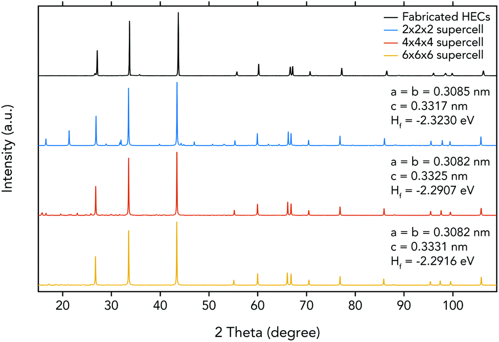 | ||
| Fig. 4 Simulated XRD patterns for DFT optimized SQS of different sizes with x = 1.0 compared with the experimentally obtained pattern. The insets show the formation enthalpy at 0 K, Hf, and the lattice parameters, a, b, and c for the fully DFT relaxed SQS (here, the angles α, β, and γ deviate less than 0.03 degrees from their theoretical values of 90, 90, and 120 degrees). | ||
Since the HEC composite is designed for high-temperature applications, the resistance to oxidation was investigated under both a moderate temperature (900 °C) for a long time and high temperature (2000 °C) for a short time. The HEC composite was heated and exposed to air for 50 hours at 900 °C. It can be seen from Fig. 5a that the change in the HEC weight was negligible throughout the measurement, which shows the resistance to oxidation of the HEC composite. We correlate this with the formation of the silica protection layer from silicon carbide on the sample surface, as was reported previously for ceramic composites containing SiC.46,47 The sample was exposed to a liquefied petroleum gas (LPG) torch, which has a flame temperature of 2000 °C,48 for 20 s. The XRD patterns of the HEC composite before and after the torch experiment (Fig. 5b) are normalized at 2θ = 27.1°. A slight increase in peak intensity at 2θ = 33.7° and 43.7°, as well as a few weakly pronounced additional diffraction peaks, was observed in the XRD pattern of the oxidized HEC composite. These XRD diffraction peaks correspond to metallic oxides, HfO2 and TaO2. The mass of the specimen shows no increase after being heated by the LPG torch in air, thus suggesting that the oxidation process was hindered, possibly because the oxidation only took place close to the specimen surface and led to a negligible mass increase. No obvious cracks are observed on the HEC composite surface after the oxidation test. Both measurements strongly suggest that the PCPed B4(HfMo2TaTi)C composite has a remarkable oxidation resistance and is desirable to serve in elevated temperature working environments.
 | ||
| Fig. 5 The PCPed HEC composite shows remarkable properties. (a) Oxidation behaviour of the HEC composite is examined by exposing to air for 50 hours at 900 °C, (b) XRD patterns of the sample exposed to liquefied petroleum gas (LPG) for 20 s in air, (c) nanoindentation of PCPed HECs shows the average hardness values (35.4 GPa) of the HEC phase, and (d) the wear resistance shows that the COF of the sintered HEC bulk material is approximately 0.5 at a load of 10 N. | ||
The nanoindentation of the PCPed HEC composite was performed on selected rectangular areas on the sample surface, showing a hardness of 35.4 GPa (Fig. 5c) and a Young's modulus of 472.4 GPa for the high-entropy phase. According to the rule of mixtures calculated from the hardness values of monolithic carbides, the theoretical hardness of the high-entropy phase is 23.2 GPa, which is 48% lower than the experimental result. The improvement of the mechanical performance over conventional carbide materials could be attributed to the solid solution hardening mechanism.21 The wear resistance test was performed under a load of 10 N with a sliding distance of 120 m and a sliding speed of 100 rpm at room temperature. The initial increase in the coefficient of friction (COF) arises from the initial process of wear creation on the sample surface. The COF curve has a flat and consistent friction coefficient of 0.5 after the break-in procedure at the beginning.49 The fluctuation of the curve is related to the lack of flatness on the sample surface. No material transfer was observed on the microstructure of the wear ball or the evaluated composite surface.
Conclusions
Six different carbides with various crystal structures were mixed and sintered using pulsed current processing (PCP). The composite contains a high-entropy ceramic (HEC) phase B4(HfMo2TaTi)C and coalesced SiCw as the second phase in the microstructure. From the experimental XRD result, a hexagonal close-packed (HCP) crystal structure was suggested. The HCP crystal structure was confirmed by DFT based crystal structure searches, and is suggested to have a layered structure with alternating metal and carbon/boron layers as a result of the independent diffusion of metal and nonmetal atoms. The formation enthalpy of the HEC solid solution at 0 K is lower than that of the precursors, pointing to energetically favorable conditions for the formation of high-entropy ceramic solid solutions during the PCP process. The HEC phase B4(HfMo2TaTi)C shows a high nanohardness (35.4 GPa), which is 48% higher than the theoretical value. The remarkable improvement in the mechanical performance is attributed to the solid solution strengthening mechanism. The high-temperature HEC composite also shows a low and consistent frictional coefficient. Moreover, the addition of SiCw contributed to the excellent oxidation resistance of the sintered HEC composite.Conflicts of interest
There are no conflicts to declare.Acknowledgements
This work was supported by the Swedish Foundation for Strategic Research (SSF) for the Infrastructure Fellowship (grant no. RIF14-0083), the National Natural Science Foundation of China (grant no. 51574241) and the bilateral project of the NSFC-STINT (grant no. 51611130064). The authors would like to acknowledge the computational resources and knowhow provided by the Swedish National Infrastructure for Computing (project SNIC 2018/3-111) at High Performance Computing Center North (HPC2N).References
- S. S. Hwang, A. L. Vasiliev and N. P. Padture, Mater. Sci. Eng., A, 2007, 464, 216–224 CrossRef.
- G. J. Zhang, Z. Y. Deng, N. Kondo, J. F. Yang and T. Ohji, J. Am. Ceram. Soc., 2000, 83, 2330–2332 CrossRef CAS.
- M. Gasch, D. Ellerby, E. Irby, S. Beckman, M. Gusman and S. Johnson, J. Mater. Sci., 2004, 39, 5925–5937 CrossRef CAS.
- E. Sani, L. Mercatelli, D. Fontani, J.-L. Sans and D. Sciti, J. Renewable Sustainable Energy, 2011, 3, 063107 CrossRef.
- J. X. Liu, Y. M. Kan and G. J. Zhang, J. Am. Ceram. Soc., 2010, 93, 370–373 CrossRef CAS.
- H.-T. Liu, J. Zou, D.-W. Ni, W.-W. Wu, Y.-M. Kan and G.-J. Zhang, Scr. Mater., 2011, 65, 37–40 CrossRef CAS.
- B. Nayebi, M. S. Asl, M. G. Kakroudi, I. Farahbakhsh and M. Shokouhimehr, Ceram. Int., 2016, 42, 17009–17015 CrossRef CAS.
- W. Fahrenholtz, G. Hilmas, A. L. Chamberlain and J. W. Zimmermann, J. Mater. Sci., 2004, 39, 5951–5957 CrossRef CAS.
- N. P. Bansal, Handbook of ceramic composites, Springer Science & Business Media, 2006 Search PubMed.
- D. Liu, Y. Gao, J. Liu, K. Li, F. Liu, Y. Wang and L. An, J. Eur. Ceram. Soc., 2016, 36, 2051–2055 CrossRef CAS.
- P. F. Becher and G. C. Wei, J. Am. Ceram. Soc., 1984, 67, C-267–C-269 CrossRef CAS.
- W. Gibbs, J. Petrovic and R. Honnell, SiC whisker-MoSi2 matrix composites, 11th Annual Conference on Composites and Advanced Ceramic Materials, 1987, pp. 645–648.
- A. L. Chamberlain, W. G. Fahrenholtz, G. E. Hilmas and D. T. Ellerby, J. Am. Ceram. Soc., 2004, 87, 1170–1172 CrossRef CAS.
- J. Gild, Y. Zhang, T. Harrington, S. Jiang, T. Hu, M. C. Quinn, W. M. Mellor, N. Zhou, K. Vecchio and J. Luo, Sci. Rep., 2016, 6, 37946 CrossRef CAS PubMed.
- W.-J. Shen, M.-H. Tsai, Y.-S. Chang and J.-W. Yeh, Thin Solid Films, 2012, 520, 6183–6188 CrossRef CAS.
- Q.-W. Xing, S.-Q. Xia, X.-H. Yan and Y. Zhang, J. Mater. Res., 2018, 33, 3347–3354 CrossRef CAS.
- Y. Zhang, T. T. Zuo, Z. Tang, M. C. Gao, K. A. Dahmen, P. K. Liaw and Z. P. Lu, Prog. Mater. Sci., 2014, 61, 1–93 CrossRef CAS.
- B. S. Murty, J.-W. Yeh and S. Ranganathan, High-entropy alloys, Butterworth-Heinemann, 2014 Search PubMed.
- J. W. Yeh, S. K. Chen, S. J. Lin, J. Y. Gan, T. S. Chin, T. T. Shun, C. H. Tsau and S. Y. Chang, Adv. Eng. Mater., 2004, 6, 299–303 CrossRef CAS.
- C. M. Rost, E. Sachet, T. Borman, A. Moballegh, E. C. Dickey, D. Hou, J. L. Jones, S. Curtarolo and J.-P. Maria, Nat. Commun., 2015, 6, 8485 CrossRef CAS PubMed.
- E. Castle, T. Csanádi, S. Grasso, J. Dusza and M. Reece, Sci. Rep., 2018, 8, 8609 CrossRef PubMed.
- D. Jianxin and S. Junlong, Ceram. Int., 2009, 35, 771–778 CrossRef.
- T. Wang, C. Ni and P. Karandikar, in Characterization of Minerals, Metals, and Materials, Springer, 2016, pp. 279–286 Search PubMed.
- C. Hwang, Q. Yang, S. Xiang, V. Domnich, A. U. Khan, K. Y. Xie, K. J. Hemker and R. A. Haber, J. Eur. Ceram. Soc., 2018, 718–725 Search PubMed.
- J.-L. Innocent, D. Portehault, G. Gouget, S. Maruyama, I. Ohkubo and T. Mori, Mater. Renewable Sustainable Energy, 2017, 6, 6 CrossRef.
- J. I. Goldstein, D. E. Newbury, J. R. Michael, N. W. Ritchie, J. H. J. Scott and D. C. Joy, Scanning electron microscopy and X-ray microanalysis, Springer, 2017 Search PubMed.
- A. Standard, ASTM E562-08, 2008 Search PubMed.
- S. Sugiyama, D. Kudo and H. Taimatsu, Mater. Trans., 2008, 49, 1644–1649 CrossRef CAS.
- K. Farhadi, A. Sabahi Namini, M. Shahedi Asl, A. Mohammadzadeh and M. Ghassemi Kakroudi, Int. J. Refract. Met. Hard Mater., 2016, 61, 84–90 CrossRef CAS.
- C. Musa, R. Orrù, D. Sciti, L. Silvestroni and G. Cao, J. Eur. Ceram. Soc., 2013, 33, 603–614 CrossRef CAS.
- F. D. Gac and J. J. Petrovic, J. Am. Ceram. Soc., 1985, 68, C-200–C-201 CrossRef.
- B. K. Agarwal, X-ray spectroscopy: an introduction, Springer, 2013 Search PubMed.
- A. J. C. Wilson, X-ray Optics: the Diffraction of X-rays by Finite and Imperfect Crystals, Methuen, 1949 Search PubMed.
- S. G. Ma and Y. Zhang, Mater. Sci. Eng., A, 2012, 532, 480–486 CrossRef CAS.
- S. Varalakshmi, M. Kamaraj and B. S. Murty, Mater. Sci. Eng., A, 2010, 527, 1027–1030 CrossRef.
- H. O. Pierson, Handbook of refractory carbides and nitrides: properties, characteristics, processing and applications, William Andrew, 1996 Search PubMed.
- S. Ghaffari, M. Faghihi-Sani, F. Golestani-Fard and M. Nojabayy, Int. J. Refract. Met. Hard Mater., 2013, 41, 180–184 CrossRef CAS.
- J. Tobin, L. Adelsberg, L. Cadoff and W. Brizes, Carbon diffusion in the group IVB and VB transition element monocarbides, Westinghouse Electric Corp., Pittsburgh, Pa., USA, Astronuclear Lab., 1965 Search PubMed.
- G. E. Hollox, Mater. Sci. Eng., 1968, 3(3), 121–137 CrossRef CAS.
- F. Zhang, S. Zhao, K. Jin, H. Bei, D. Popov, C. Park, J. C. Neuefeind, W. J. Weber and Y. Zhang, Appl. Phys. Lett., 2017, 110, 011902 CrossRef.
- W. Hume-Rothery, Phase stability in metals and alloys, McGraw-Hill, New York, 1967, p. 3 Search PubMed.
- D. C. Lonie and E. Zurek, Comput. Phys. Commun., 2011, 182, 2305–2306 CrossRef CAS.
- G. Kresse and J. Furthmüller, Phys. Rev. B: Condens. Matter Mater. Phys., 1996, 54, 11169–11186 CrossRef CAS.
- M. C. Gao, J.-W. Yeh, P. K. Liaw and Y. Zhang, High-Entropy Alloys, Springer, 2016 Search PubMed.
- A. van de Walle, P. Tiwary, M. de Jong, D. L. Olmsted, M. Asta, A. Dick, D. Shin, Y. Wang, L. Q. Chen and Z. K. Liu, Calphad, 2013, 42, 13–18 CrossRef CAS.
- I. N. Godovannaya and O. I. Popova, in Chemical Properties and Analysis of Refractory Compounds/Khimicheskie Svoistva I Metody Analiza Tugoplavkikh Soedinenii/Химические Свойства И Методы Анализа Тугоплавких Соединений, ed. G. V. Samsonov, Springer US, Boston, MA, 1972, pp. 33–35, DOI:10.1007/978-1-4615-8555-8_7.
- K. Upadhya, J. Yang and W. Hoffman, Am. Ceram. Soc. Bull., 1997, 76, 51–56 CAS.
- D. Carinhana Jr., L. G. Barreta, C. J. Rocha, A. M. D. Santos and C. A. Bertran, J. Braz. Chem. Soc., 2008, 19, 1326–1335 CrossRef.
- T. Chapman, D. Niesz, R. Fox and T. Fawcett, Wear, 1999, 236, 81–87 CrossRef CAS.
Footnote |
| † Electronic supplementary information (ESI) available. See DOI: 10.1039/c8dt04555k |
| This journal is © The Royal Society of Chemistry 2019 |