
 Open Access Article
 This Open Access Article is licensed under a Creative Commons Attribution-Non Commercial 3.0 Unported Licence
Tunable colloidal Ni nanoparticles confined and redistributed in mesoporous silica for CO2 methanation†
Wilbert L.
Vrijburg
 a,
Jolanda W. A.
van Helden
a,
Arno J. F.
van Hoof
a,
Heiner
Friedrich
a,
Esther
Groeneveld
b,
Evgeny A.
Pidko‡
*a and
Emiel J. M.
Hensen
*a
a,
Jolanda W. A.
van Helden
a,
Arno J. F.
van Hoof
a,
Heiner
Friedrich
a,
Esther
Groeneveld
b,
Evgeny A.
Pidko‡
*a and
Emiel J. M.
Hensen
*a
aLaboratory of Inorganic Materials and Catalysis, Schuit Institute of Catalysis, Eindhoven University of Technology, P.O. Box 513, 5600 MB Eindhoven, The Netherlands. E-mail: e.a.pidko@tudelft.nl; e.j.m.hensen@tue.nl
bBASF Nederland B.V., De Meern, The Netherlands
First published on 22nd April 2019
Abstract
Herein we report our efforts to control the size of colloidal Ni nanoparticles (NiNPs) via a seed-mediated approach and to produce supported Ni catalysts that are sinter-resistant. NiNPs are prepared using a mild capping ligand and an external reducing agent at 90 °C to obtain seeds of 3–4 nm, followed by NiNP growth at 220 °C to vary the final size up to 8 nm. These NiNPs were either introduced onto high surface area silica via direct deposition in organic solvents, or encapsulated in mesoporous silica. Encapsulation was determined to be the most promising approach to support the particles. A range of such encapsulated NiNP catalysts were evaluated for CO2 hydrogenation between 200–400 °C: they were comparably active as catalysts reported in the literature, and thermally stable and sinter-resistant for 70 h at 350 °C. Nevertheless, it was found that the Ni phase was redistributed throughout the mesoporous silica network, resulting in Ni catalysts with nearly identical particle size of 4–5 nm, determined by the size of the support pores, after a combination of oxidative and reductive pretreatments. Our approach provides a route to obtain Ni@SiO2 catalysts with a narrow particle size distribution from a range of colloidal NiNP precursors.
1 Introduction
Colloidal routes towards supported metal catalysts have long been proposed as a strategy to obtain well-defined heterogeneous catalysts due to the possibility to control nanoparticle size and shape.1,2 The flexibility in colloidal preparation routes are often viewed as advantageous over conventional catalyst synthesis methods such as impregnation or coprecipitation.3,4 Both particle size and shape are known to significantly influence the catalytic activity of supported nanoparticles in structure–sensitive reactions such as Fischer–Tropsch and CO2 reduction.5–9 Despite the perceived advantages for colloidal synthetic approaches, most studies have focused on producing noble metal catalysts,10 with industrially relevant metals such as Ni and Co receiving limited attention.The synthesis of supported metal catalysts via colloidal approaches involves two main challenges related to (i) the control of the nanoparticle size and (ii) the controlled deposition of the colloidal nanoparticles onto a support and the removal of the capping ligands to obtain active catalysts. The former challenge has received more attention than the latter, even though the deposition step is crucial to obtain active and stable catalysts.11 Ineffective anchoring of the nanoparticles may lead to significant particle aggregation during high-temperature activation, whereas low temperature treatments may not effectively remove the capping ligands.12,13 Good control over nanoparticle deposition on oxidic supports is particularly important for Ni, which is susceptible to particle sintering. Moreover, despite several studies in recent years aiming to control Ni nanoparticle (NiNP) size, only limited studies have provided synthetic approaches that yielded NiNPs between 1–10 nm, which that were then also deposited on a support to investigate particle sintering after capping agent removal.14
Colloidal nanoparticles are comprised of a metallic core stabilized by long-chain organic ligands (capping/stabilizing agents). Vital to obtaining homogeneously dispersed nanoparticles are homogeneous seed formation (nucleation) of metallic monomers, induced by metal atom (monomer) concentrations surpassing a threshold concentration (supersaturation). Nucleation stops once the monomer concentration drops below the supersaturation concentration, with existing nuclei consuming the remaining monomers in the organic solution (heterogeneous nucleation).15 Synthetic routes to produce NiNPs have usually involved either (i) thermal decomposition of an organometallic precursor to produce and grow the nuclei, or (ii) inducing nucleation using an external reducing agent to reduce Ni2+, either as organometallic complex or salt, to metallic Ni0. In thermal decomposition procedures, Ni is usually reduced by the capping agents present in the solution.16
Thermal decomposition methods for NiNP synthesis have been extensively explored, with Ni(acac)2 often employed as the Ni precursor. Zhang et al. studied the influence of temperature on NiNP size employing only oleylamine (OAm) as both solvent and capping agent.17 Polydispersed particles with a mean diameter of 22 nm were obtained after nucleation and growth at 220 °C, while nucleation was already found to start at 180 °C. A narrow particle size distribution for 20–60 nm NiNPs could be obtained by separating the seed and growth steps in the synthesis. To achieve this, a two-step seed-growth approach was introduced, in which the initial seeds formed at 220 °C could be grown more homogeneously by introducing additional precursor at room temperature and then maintaining the solution at 195 °C. Chen et al. explored a variety of alkylamines as capping agents and reducing agents when preparing NiNPs via thermal decomposition routes, obtaining particles between 10–50 nm.18
In order to improve control over particle sizes, many studies resorted to stronger capping agents. These have primarily involved phosphorous containing ligands,18–23 although sulfur containing agents have also been explored.24,25 Winnischofer et al. screened various ratios of Ni precursors, phosphine, and amine functionalized ligands to control Ni particle sizes between 4.8–16.3 nm.26 Carenco et al. studied the growth mechanism of NiNPs, employing a combination of trioctylphosphine (TOP) and OAm as capping agents.19 Within their work, the authors determined OAm to be an effective reducing agent (and therefore nucleation agent) but a weak capping agent, whereas the phosphine ligand was an efficient capping agent but poor reducing agent for Ni(acac)2. The exclusive use of OAm as both capping and reducing agent led to Ni particles between 50–80 nm under thermal reduction conditions. Their understanding of the nucleation and growth mechanism allowed the authors to tailor particle sizes from 2 to 30 nm by varying the OAm![[thin space (1/6-em)]](https://www.rsc.org/images/entities/char_2009.gif) :TOP ratio, with TOP-only mixtures yielding the smallest particle sizes with a mean diameter of 2 nm.
:TOP ratio, with TOP-only mixtures yielding the smallest particle sizes with a mean diameter of 2 nm.
The key problem with employing phosphorous containing ligands (P-ligands) is that the phosphorous is inevitably incorporated into the Ni lattice, even at temperatures below 220 °C.19,27–29 Calcination at 500 °C was found to be insufficient to remove phosphorous from deposited NiNPs, yielding supported P-containing Ni nanoparticles which were inactive in cyclohexene hydrogenation.30 However, Ni-phosphides were not observed by XRD and the predominant phase in the synthesized NiNPs was metallic Ni. Similar effects have also been observed for Co-based NPs.31 The use of P-containing ligands should therefore be avoided if Ni- and Co-based hydrogenation catalysts are desired.
Thermal decomposition strategies alone are insufficient to achieve particle size control in the absence of P-ligands, particularly if Ni(acac)2 is employed as the Ni precursor. In addition to thermal reduction strategies the use of strong reducing agents such as NaBH4,32,33 hydrazine,34–36 polyols,37 and more recently borane tert-butylamine (BTB) complex have been explored.38,39 Using OAm and oleic acid (OAc) as co-surfactants at 90 °C, Metin and co-workers were able to synthesize monodisperse NiNPs from 3.2 to 5.4 nm by lowering the BTB/Ni ratio from 3/1 to 1/1 respectively.38 Particles smaller than 3 nm were obtained by Li et al. by increasing the temperature at which BTB was injected into the Ni(acac)2 solution from 90 °C to 180 °C.40 However, particle size control to obtain a series of larger particles between 4 to 10 nm was not achieved, which could be desirable when employed in structure–sensitive catalytic reactions such as CO and CO2 hydrogenation.5–8
In addition to accurately controlling the particle size of colloidal NiNPs, their effective and controlled deposition on oxidic supports and subsequent removal of the organic ligands are vital to obtain active and well-defined catalysts. Direct deposition via impregnation methods are facile,1 but Ni is prone to sintering during ligand removal by calcination at elevated temperatures.30 Rinaldi et al. deposited NiNPs on SiO2 and found that high temperature treatments, although effective at reducing the amount of ligands on the NiNP surface, also increased the particle mobility which led to significant sintering from 5 nm to 20 nm after reduction at 500 °C.30 Zacharaki et al. successfully deposited NiNPs on Al2O3 and effectively removed the ligands by thermal treatment with only slight sintering observed after reduction at 400 °C. Complete reduction was not achieved though, and this is necessary for hydrogenation catalysis.14 More robust methods must therefore be developed to support well-defined colloidal nanoparticles and to maintain their dispersion if colloidal routes are to be considered a beneficial approach. To this end, nanoparticle confinement in porous matrices is considered a viable strategy. The stabilization of small (<2 nm) NiNPs through confinement in zeolite micropores has been investigated by Laprune et al.41 and Goodarzi et al.42 Brock and co-workers successfully encapsulated Ni2P colloidal nanoparticles (d = 11 nm) in mesoporous silica to prevent their aggregation after ligand removal and catalyst activation.43 Such strategies have been studied for supporting colloidal Pt and Pd nanoparticles,44–47 as well as phosphorous-free colloidal NiNPs,48–50 although these NiNP studies sought to support and stabilize particles larger than 20 nm. At present, no study has been able to produce well-defined colloidal NiNPs which vary in particle size and maintain their dispersion once supported and thermally activated (i.e. ligand removal and catalyst reduction), and are active in gas phase hydrogenation reactions. Ideally, such an approach would lead to catalysts that are tailored for a specific structure–sensitive reaction.
In this work, we report the preparation of mesoporous silica supported NiNPs prepared via the colloidal approach. By building a comprehensive set of colloidal NiNPs, we are able to isolate important factors controlling growth and nucleation using established colloidal nanoparticle growth theory. A two-step seed-mediated synthetic approach was developed, in which NiNP nucleation was induced with an external reducing agent under mild conditions. Particles were subsequently grown under thermal decomposition conditions (>200 °C) to obtain NiNPs between 3–8 nm using P-free ligands. Next, strategies to support the colloidal NiNPs and remove their ligands were investigated. Encapsulation of NiNPs in mesoporous silica produced active and stable hydrogenation catalysts. Moreover, encapsulation of colloidal NiNPs of different sizes ultimately led to a redistribution of the encapsulated Ni to yield catalysts with identical particle sizes and substantial catalytic activity. This approach demonstrates that colloidal NiNP growth can be effectively controlled using only mild capping agents, but that the support pore size becomes the controlling factor of the final NiNP size in encapsulated Ni@SiO2 hydrogenation catalysts.
2 Experimental
2.1 Materials
Nickel acetylacetonate (anhydrous, 95%) was purchased from Strem, and oleylamine (OAm, technical, >70%), oleic acid (OAc, 90%), borane tert-butylamine complex (BTB, 97%), and cetrimonium bromide (CTAB, >99%) from Sigma Aldrich. Amorphous silica (Sipernat® 50 S, surface area 500 m2 g−1) was purchased from Evonik. Hexane (99%), toluene (99.7%), CHCl3 (99.9%, stab./amylene) were purchased from Biosolve, and tetraethyl orthosilicate (TEOS, >99%) from Merck. All chemicals were used as received without further purification.2.2 Colloidal nanoparticle synthesis
Ni nanoparticles between 3–8 nm were synthesized using seed-mediated growth methods based on a combination of literature approaches.19,38,39 To obtain the smallest particles (seeds), 257 mg Ni(acac)2 (1 mmol), 15 mL oleylamine (OAm) and 0.32 mL oleic acid (OAc, 1 mmol) were added to a 250 mL two-neck round-bottomed flask equipped with a magnetic stirring bar. The mixture was brought under inert conditions by flushing with Ar and degassed at 110 °C for 30 min to removed oxygen and water. A green–blue solution was obtained. In a second flask, 0.44 g borane tert-butyl amine complex (BTB, 5 mmol) was dissolved in 2 mL OAm and degassed. The Ni(acac)2 solution was cooled to 90 °C and the BTB solution was subsequently injected into the Ni(acac)2 solution. The mixture went black within 30 s, signaling the reduction of the Ni2+ to metallic Ni. The synthesis continued for 1 h, after which the reaction was quenched by adding 17 mL toluene and cooled to room temperature. Nanoparticles were precipitated by adding acetone as an anti-solvent, followed by centrifugation (5000 rpm, 10 min). The supernatant was removed and the particles were washed by redispersing them in 5 mL toluene, followed by precipitation with 45 mL acetone and centrifugation. Particles were washed 3 times with the toluene/acetone mixture.To obtain larger particles, the seeds were grown at elevated temperatures. After 1 h of the initial seed formation (as described above), the black solution was heated to 220 °C using a heating mantle. Additional Ni(acac)2 (2–4 mmol) in equimolar OAc (2–4 mmol) was dissolved in octadecene (ODE, 10–20 mL) and was added dropwise to the round-bottomed flask using a Teflon cannula at a rate of ca. 0.5 mL min−1. The particles were kept at 220 °C for an additional 1.5 h, after which the heating mantle was removed. Toluene was added to make a 1:1 solution with the colloidal NPs. Nanoparticles were precipitated, collected, and washed according to the procedure outlined above.
2.3 Supported colloidal nanoparticles
In order to remove the organic ligands (OAm/OAc) and templating/stabilizing agent (CTAB), Ni@SiO2 was calcined in 20 vol% O2 in N2 mixture (50 mL min−1) at 500 °C (1 °C min−1, 10 h). The oxidized NiO@SiO2 nanoparticles were reduced at 450–550 °C in 10 vol% H2 in He flow (2.5 °C min−1, 6 h).
2.4 Characterization
2.5 Catalytic activity measurements
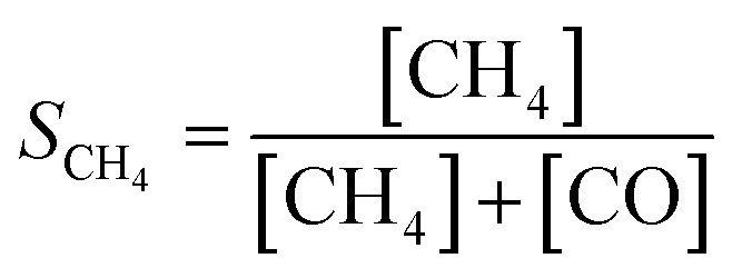
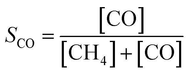
The catalytic activity of the prepared samples for gas-phase hydrogenation reactions was performed in a 10-channel high-throughput flow reactor. Prepared samples were pelletized at a pressure of 300 MPa and sieved to a 75–125 μm fraction. Approximately 50 mg catalyst (75–125 μm) was diluted with 150 mg SiC and loaded into a quartz reactor tube with an internal diameter of 0.4 cm. Quartz wool was used before and after the catalyst bed. Effluent products were analyzed by online gas chromatography (Interscience CompactGC) equipped with Restek Rt-Q-Bond and Rt-Msieve 5 Å (TCD), Restek Rt-U-Bond and Rt-Q-Bond (TCD), and Restek Rtx-1 (FID) columns.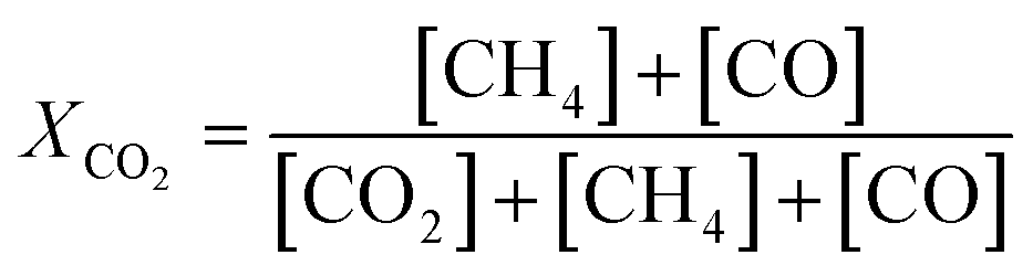 | (1) |
 | (2) |
 | (3) |
3 Results and discussion
3.1 Ni particle size control
The general procedures for the colloidal synthesis of Ni nanoparticles employed here are summarized in Fig. 1 with the main results summarized in Table 1. Representative TEM images for obtained NiNPs are shown in Fig. 2. Benchmark procedure 1 involved the synthesis of the colloidal NiNPs through thermal decomposition of Ni(acac)2 in the presence of an equimolar amount of oleic acid (OAc) and excess oleylamine (OAm) at 220 °C. OAc was used as a co-surfactant to efficiently solvate Ni2+ in the non-polar organic solution. This procedure resulted in polydisperse NiNPs with an average particle size of 53 nm (Fig. 2a), despite the large excess of 46 equivalent of OAm. The results are consistent with earlier reports by Zhang et al.17 and Carenco et al.19 Previously, the large sizes and broad size distribution of the NPs were attributed to the rapid reduction of Ni2+ to Ni(0) by OAm, leading to a burst of Ni(0) species which could not be effectively stabilized by OAm and therefore aggregate into polydisperse particles.19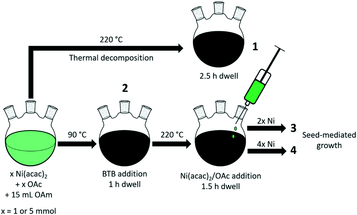 | ||
| Fig. 1 Schematic illustration of Ni nanoparticle synthesis procedures 1–4. | ||
| Procedure | Initial Ni(acac)2 (mmol) | BTB/Ni | T (°C) | Ni(acac)2 added (mmol) | d (nm) | Fraction Ni0b (%) |
|---|---|---|---|---|---|---|
| a BTB injection at 90 °C, Ni(acac)2 addition at 220 °C. b Air exposed. Surface fraction determined by XPS. | ||||||
| 1 | 5 | n/a | 220 | 0 | 53 (± 14) | 47 |
| 2 | 1 | 5 | 90 | 0 | 4.4 (± 0.5) | 22 |
| 3a | 1 | 5 | 90, 220 | 2 | 6.3 (± 1.0) | 12 |
| 4a | 1 | 5 | 90, 220 | 4 | 7.9 (± 1.5) | 39 |
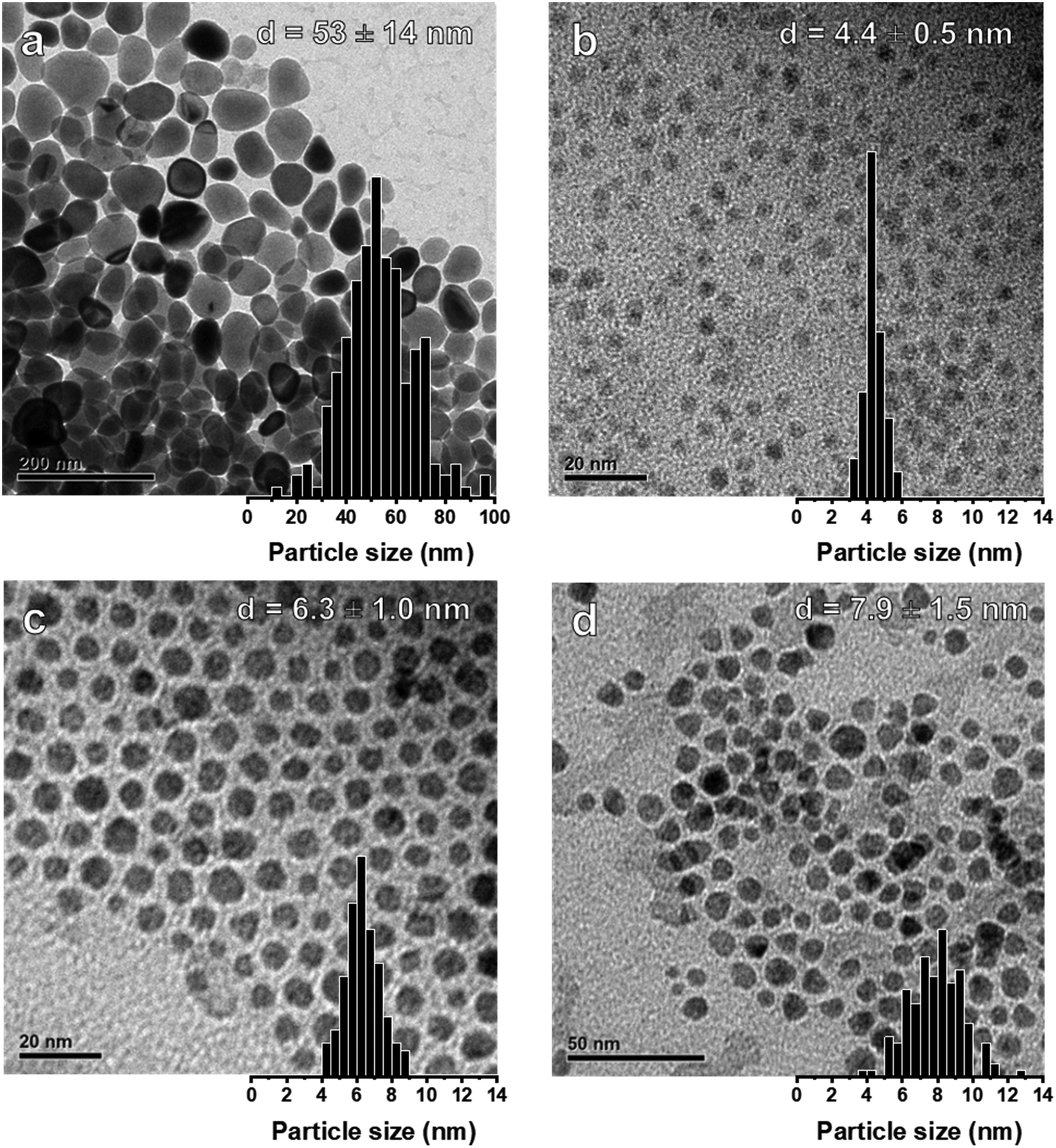 | ||
| Fig. 2 (a) TEM image and distribution of colloidal NiNPs prepared by thermal decomposition of Ni(acac)2 in OAm at 220 °C (procedure 1). Colloidal NiNPs prepared using seed-mediated growth methods: (b) initial particles produced with BTB/Ni = 5 at 90 °C (procedure 2). By increasing the temperature to 220 °C, particles were grown by the dropwise addition of (c) 2 equivalents (procedure 3) or (d) 4 equivalents (procedure 4) Ni(acac)2 in an OAc/ODE solution. | ||
To obtain smaller particles with a narrower size distribution, lower-temperature procedures (90 °C) with an external reducing agent were applied (procedures 2–4, Fig. 1, Table 1).38 Borane tert-butylamine (BTB) was dissolved in OAm and injected into the Ni(acac)2/OAc/OAm solution, turning the mixture black almost instantly (procedure 2). The rapid injection of the external reducing agent leads to a supersaturated solution during which particle nucleation occurs. It is vital that this step is carried out rapidly to achieve homogeneous nucleation and obtain colloidal NPs with a narrow particle size distribution. TEM images confirm that nanoparticles of 4.4 nm were obtained for BTB/Ni = 5 after 1 h growth at 90 °C (Fig. 2b). After precipitating out the NiNPs using a toluene/acetone mixture, the remaining supernatant still appeared slightly green, suggesting that not all the Ni2+ had been reduced.
To obtain larger particles, the nanoparticles were pre-formed at 90 °C and rapidly heated to 220 °C. Additional Ni(acac)2 (2 or 4 mmol) dissolved in OAc (2 or 4 mmol, respectively) and ODE (10 or 20 mmol, respectively) was added dropwise to the colloidal dispersion (procedures 3 and 4 respectively, Fig. 1, Table 1). NiNPs of 6.3 nm and 7.9 nm were obtained in this way by the addition of 2 mmol and 4 mmol Ni(acac)2 to the initial suspension at 220 °C. The Ni2+ concentration and the rate of addition were kept constant during the different procedures.
Structural properties of as-synthesized colloidal NiNPs were studied by XRD (Fig. 3). NiNPs synthesized via the BTB reduction pathway (procedures 2–4) did not exhibit crystalline phases in XRD which we attribute to the small particle size.51,52 Low-intensity contributions between 40–45° are likely from amorphous carbon deposits. In contrast, the XRD pattern of NiNPs synthesized by direct thermal decomposition of Ni(acac)2 showed sharp diffraction peaks at 39.1°, 41.6°, 44.6°, 58.4°, 71.0°, and 78.0° correspond to the (100), (002), (101), (102), (110), and (103) crystal planes of hcp-Ni3C (JCPDS no. 04-0853). The hexagonal lattice constants of a = 2.65 Å and c = 4.35 Å match those reported in literature for hcp-Ni3C.53–55 Colloidal routes providing Ni3C nanoparticles have been reported before during synthesis carried out above 200 °C, with carbon contaminations of the organic surfactants yielding the carbide phase.54–57 However, due to the nearly similar lattice parameters of hcp-Ni3C and metastable hcp-Ni, we cannot only rely on XRD to discern between these two crystal phases.53 The carbide phase was confirmed by XPS measurements of the C 1s region (see ESI†). By etching the NiNP surface with Ar+ ions, a peak positioned at 283.5 eV emerged, which could be attributed to the Ni–C bond.54 This phase is metastable and decomposes into fcc-Ni in reducing atmospheres above 300 °C.58,59 XPS measurements of the C 1s region after Ar+ etching did not reveal a Ni–C phase for these smaller NiNPs (see ESI†).
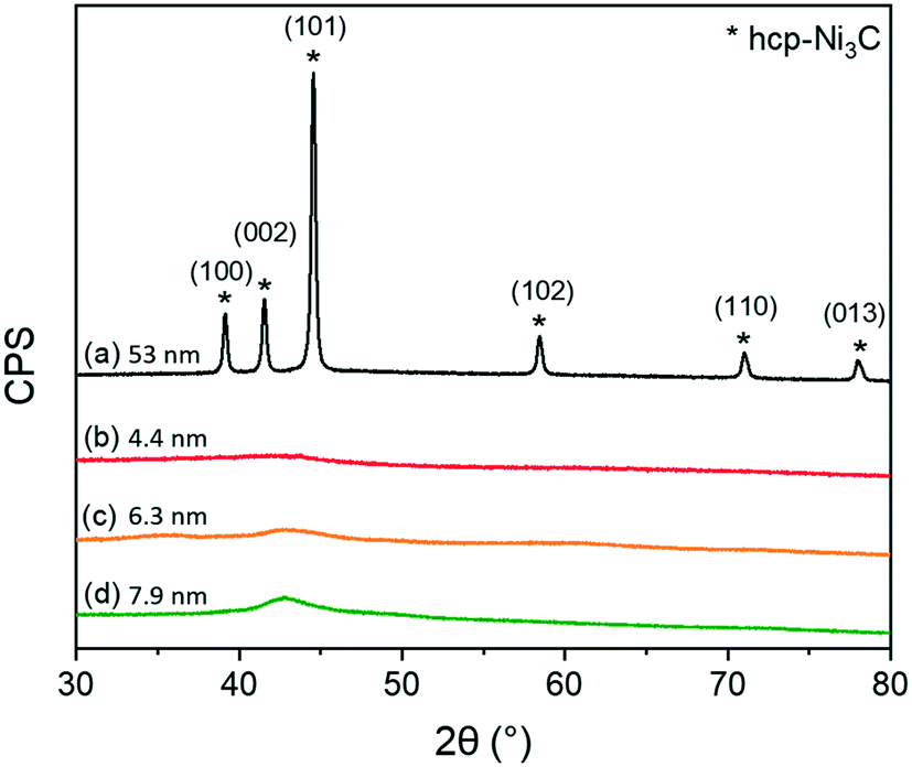 | ||
| Fig. 3 XRD patterns for the colloidal NiNPs synthesized by (a) thermal decomposition at 220 °C (procedure 1), (b) BTB addition at 90 °C to give the smallest NiNPs (procedure 2). Seed-mediated approaches were ramped to 220 °C and either (c) 2 equivalents (procedure 3) or (d) 4 equivalents of Ni(acac)2 (procedure 4) was added dropwise. | ||
The nature of the particles was studied further with XPS. XP spectra of colloidal NiNPs after exposure to air were obtained in the Ni 2p3/2 region (Fig. 4). Despite the absence of oxidic Ni phases in XRD, we observed both metallic Ni0 (BE = 852.8 eV) as well as oxidized Ni2+ (main peak BE = 856.0 eV, satellite peak BE = 861.5 eV) on all NiNPs, confirming that the NiNPs readily passivated in air. Larger colloidal NiNPs appeared to be more resistant to passivation as evidenced by a higher Ni0 fraction (Table 1).
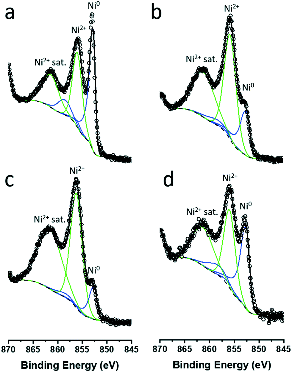 | ||
| Fig. 4 Fitted XP spectra in the Ni 2p3/2 region of colloidal NiNPs synthesized by (a) thermal decomposition at 220 °C (procedure 1, d = 53 nm), and (b) BTB addition at 90 °C (procedure 2, d = 4.4 nm). XP spectra of NiNPs obtained synthesized by seed formation at 90 °C and particle growth at 220 °C by (c) 2 eq. Ni addition (procedure 3, d = 6.3 nm), and (d) 4 eq. Ni addition (procedure 4, d = 7.9 nm). Open circles represent raw data, and metallic Ni0 (blue) and Ni2+ (green) contributions were fitted. | ||
Interestingly, our results demonstrate that OAm is an effective capping agent at temperatures at which Ni(acac)2 decomposes (>200 °C).60 This result contrasts earlier findings by Carenco et al., who determined OAm to be a weak capping agent under thermal decomposition conditions, leading to large, polydispersed nanoparticles.19 Based on our data, we speculate that OAm is an adequate capping agent but a poor reducing agent, resulting in an ineffective nucleation and slow growth. The theory of colloidal nanoparticle growth has been reviewed in great detail elsewhere.1,3,15,61,62 In the absence of an external reducing agent, atomic Ni monomer formation is kinetically limited during the temperature ramp to 220 °C. Therefore, once (local) supersaturation is achieved, Ni seeds are formed and the monomer concentration decreases below the threshold concentration for nucleation. However, due to the slow Ni(acac)2 decomposition, relatively few seeds are formed when compared to an approach employing an external reducing agent. The low seed concentration leads to large particles. Moreover, as decomposition kinetics increase at higher temperature, the rate of monomer formation is also increased. If the monomer concentration exceeds the threshold concentration required for supersaturation, nucleation will occur resulting in the formation of new seeds. The formation of new seeds during the growth of existing seeds is the main cause of the broad particle size distribution. With our seed-mediated approach, we obtain a rapid increase in monomer concentration at low temperatures which leads to homogeneous nucleation. These particles maintain their narrow size distribution upon increasing the temperature to 220 °C. Further addition of Ni(acac)2 under decomposition conditions maintains a low monomer concentration and grows the existing particles rather than nucleating new ones. Overall this approach allows a better control of NiNP synthesis. In contrast, addition of Ni(acac)2 at 90 °C did not result in the formation of larger particles, but in a higher yield of NiNP (see the ESI†), confirming that the low-temperature seed formation must be combined with the high-temperature particle growth to obtain larger particles. To the best of our knowledge, this is the first report of seed-mediated NiNPs able to control nanoparticle growth below 10 nm, with earlier studies reporting particles larger than 25 nm.17
3.2 Colloidal Ni/SiO2
Initially, two approaches were explored to support pre-synthesized colloidal NiNPs: direct deposition on SiO2 and encapsulation in SiO2. An initial set of 3 catalyst samples were prepared via direct deposition by contacting the colloidal NiNPs with a commercial SiO2 support. The NiNPs were either dispersed in hexane (Ni/SiO2-h), toluene (Ni/SiO2-t), or chloroform (Ni/SiO2-c). Alternatively, colloidal NiNPs were encapsulated by first dispersing the particles in CHCl3, adding the dispersion into a CTAB solution. CHCl3 was removed by evaporation at 75 °C to yield CTAB-stabilized, OAm capped colloidal NiNPs in H2O.43 This double-micelle approach stabilizes the hydrophobic colloidal nanoparticles in aqueous media. Particles were encapsulated in SiO2 by adding the molecular silicon precursor TEOS under basic conditions. The hydrolysis of TEOS and condensation of silica was allowed to proceed for at least 12 h. The sample was washed extensively and calcined at 500 °C to remove all templating agents. For all samples, low Ni loadings (ca. 1–2 wt%) were used to minimize particle aggregation during ligand removal and catalyst activation, both achieved by reduction in 10 vol% H2 in He at 450 °C. All samples had initial colloidal NiNP sizes around 3.5 nm (Table 2), achieved by following procedure 2 and allowing only 5 min growth time. These particles were only used in this initial screening study.| Sample | Solvent | wt% Ni | d 1 (±), nm |
|---|---|---|---|
| Ni/SiO2-h | Hexane | 2.1 | 3.4 (0.5) |
| Ni/SiO2-t | Toluene | 0.7 | 3.7 (0.7) |
| Ni/SiO2-c | CHCl3 | 1.2 | 3.7 (0.7) |
| Ni@SiO2 | CHCl3/H2O | 1.2 | 3.7 (0.7) |
TEM images obtained for directly deposited NiNPs after reductive treatment at 450 °C are presented in Fig. 5a–c. The images highlight the differences in the aggregation of the Ni phase. A weak interaction between the commercial SiO2 and colloidal NiNPs led to ineffective anchoring of the NiNPs, as evident from the sintering after reduction. In contrast, encapsulated nanoparticles (Fig. 5d) retained their initial particle size (3.5 ± 0.5 nm), even after reduction at 550 °C.
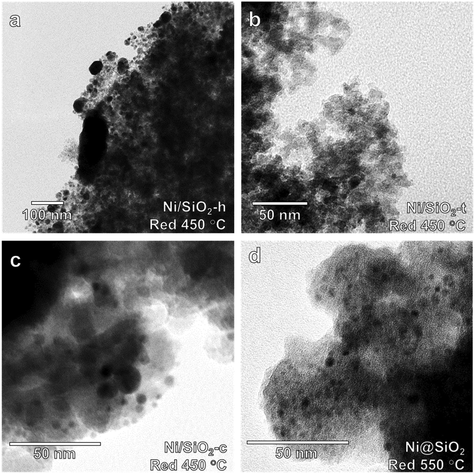 | ||
| Fig. 5 TEM micrographs of (a) hexane, (b) toluene, and (c) chloroform suspended NiNPs deposited on amorphous SiO2 after reduction at 450 °C. (d) NiNPs encapsulated in mesoporous SiO2 after reduction at 550 °C showing an average particle size of 3.5 nm. | ||
To verify the potential of these samples for catalysis, they were employed in the gas-phase benzene hydrogenation to cyclohexane. This reaction, regarded as structure-insensitive, probes the hydrogenation properties of the supported colloidal nanoparticles. Fig. 6 shows turnover frequencies (TOFs) measured at 100 °C normalized to the total Ni content for the supported and encapsulated NiNPs. Hexane deposited NPs were not studied due to the significant sintering observed by TEM. After reduction at 450 °C, the encapsulated NiNPs were more active than the directly deposited particles. Pre-calcination of directly deposited NiNPs did not improve the catalytic performance of these materials (ESI†). Clearly, encapsulation of NiNPs yielded superior performing catalysts compared to direct deposition, showing significantly higher hydrogenation activity after catalysts were reduced at 450 °C. We also found that reduction at 550 °C led to even higher activity for the encapsulated NiNPs, whereas this treatment strongly decreased the performance of the deposited NiNP catalyst. The high activity after reduction at 550 °C should be due to a higher reduction degree, whilst this positive effect is suppressed by sintering for the deposited NiNP catalyst. Although sintering was observed for Ni/SiO2-t, this sample surprisingly was not active at all. Based on these results, we conclude that supporting the NiNPs by encapsulation is the most viable approach to study particle size effects in supported Ni catalysts and proceeded to investigate this synthetic route in greater detail.
 | ||
| Fig. 6 Gas-phase benzene hydrogenation TOFs at 100 °C over encapsulated Ni@SiO2, Ni/SiO2-c and Ni/SiO2-t after reduction at 450 °C and 550 °C. | ||
3.3 Encapsulation of NiNPs in mesoporous SiO2
Having optimized both NiNP synthesis and NiNP supporting techniques, a set of encapsulated Ni(x)@SiO2 catalysts was prepared in which x denotes the original NiNP size. Procedures 2, 3, and 4 were used to synthesize the NiNPs of 4.4 nm, 6.8 nm, and 7.2 nm respectively. The new set of colloidal nanoparticles were similar in size compared with those obtained in the earlier synthesis optimization work, highlighting the method's reproducibility. Particles of 5.0 nm were obtained by rapid heating of the initial BTB/Ni solution from 90 °C to 220 °C without injecting additional Ni(acac)2 under thermal decomposition conditions, indicating that unreduced Ni2+ at 90 °C may still be reduced at 220 °C, growing the existing NiNPs from ca. 4.4 to 5.0 nm. After extensive washing and vacuum drying, approximately 200 mg colloidal NiNPs was supported via encapsulation. Ligand and templating agents were removed by slow calcination at 500 °C (10 h, 1 °C min−1), as determined by TGA analysis (see ESI†). Ni content and physical characterization of calcined materials are summarized in Table 3. BET surface areas were determined by N2 physisorption (see ESI†) and were high for all catalysts, ranging between about 890–980 m2 g−1.| Sample | Ni wt%a | BET (m2 g−1) | V tot (cm3 g−1) | Pore sizeb (nm) | H2 chem. (mmol g−1) | Accessible metallic Ni (%) | d (nm) | |
|---|---|---|---|---|---|---|---|---|
| H2 chem. | HAADF-STEMc | |||||||
| a Determined with ICP-OES after calcination at 500 °C. b Determined from d-spacing using the position of the SiO2 (100) diffraction obtained from low-angle XRD measurements. c Samples were reduced at 600 °C (10 vol% H2) and passivated at RT (1 vol% O2, 6 h). | ||||||||
| Ni(4.4) | 2.4 | 979 | 1.46 | 4.4 | 0.019 | 9.1 | 11.1 | 4.3 (± 0.6) |
| Ni(5.0) | 4.8 | 983 | 1.74 | 4.9 | 0.052 | 12.9 | 7.9 | 4.6 (± 0.6) |
| Ni(6.8) | 3.7 | 964 | 2.15 | 4.7 | 0.036 | 11.4 | 8.9 | 4.7 (± 0.7) |
| Ni(7.2) | 8.6 | 891 | 1.18 | 5.4 | 0.087 | 11.8 | 8.6 | 4.6 (± 0.6) |
Further characterization with XRD (Fig. 7) showed that the catalysts were largely amorphous after calcination. The broad reflection around 22° is characteristic of amorphous silica. NiO reflections were only observed for the higher loaded Ni(7.2)@SiO2 and to a lesser extent Ni(5.0)@SiO2 catalysts. Sharp reflections from (200) and (220) planes were observed around 43.7° and 64.0°, respectively, indicating the formation of large NiO crystallites (JCPDS no. 47-1049), which we verified with HAADF-STEM (ESI†). Moreover, very weak and broad contributions centered around 35.2° (envelope of two reflection peaks) and 61.0° are indicative of a Ni-silicate phase (JCPDS no. 49-1859).63,64 This was a first indicator that the nanoparticle-like structure of NiNPs is lost during calcination. Low-angle XRD measurements (Fig. 7b) confirmed the presence of MCM-41 like mesoporous structures in all catalysts. The average mesopore size was calculated from the d-spacing derived from the position of the (100) reflection and ranged from 4.4 nm for Ni(4.4)@SiO2, to 5.4 nm for Ni(7.2)@SiO2 (Table 3).
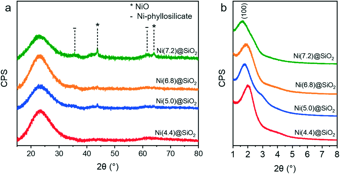 | ||
| Fig. 7 (a) Wide angle XRD patterns of encapsulated NiNPs after calcination at 500 °C (10 h, 1 °C min−1). (b) Small-angle XRD confirming the presence of MCM-41 like mesopores for all catalysts. | ||
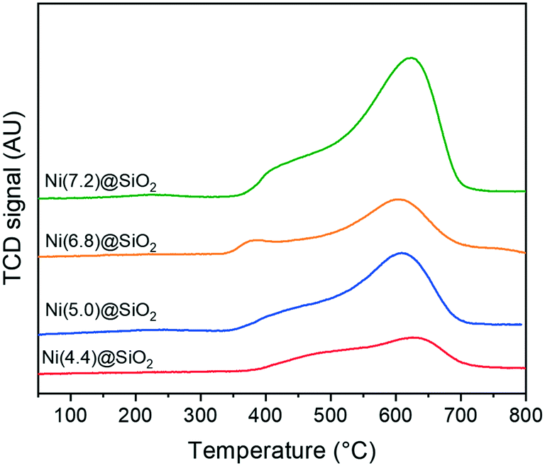
Crucial to the catalytic activity of Ni-based hydrogenation catalysts is the reducibility of Ni and the availability of metallic Ni active sites. Fig. 8 shows the TPR profiles of encapsulated nanoparticles after calcination. All catalysts exhibit a maximum reduction temperature between 600–650 °C, which is characteristic of Ni strongly interacting with the support. Shoulders around 450 °C can be attributed to the reduction of NiO weakly interacting with SiO2. Moreover, the total hydrogen consumption scales with the total Ni content, whilst the TPR profiles are composed of similar features.
 | ||
| Fig. 8 H2-TPR profiles of Ni(x)@SiO2 catalysts. | ||
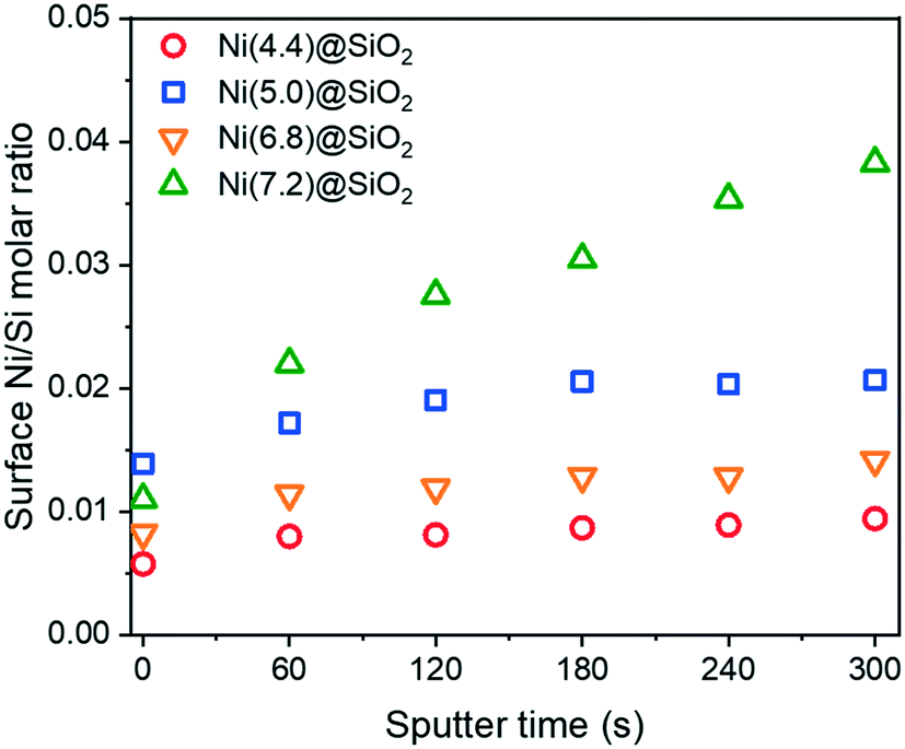
Further verification that the Ni was encapsulated after reduction was achieved with XPS depth-profiling. Fig. 9 shows surface Ni/Si molar ratios upon successive Ar+ etching. Samples were first reduced ex situ at 600 °C in 10 vol% H2 in He and passivated in 1 vol% O2. After Ar+ etching for 60 s, all samples exhibited higher Ni/Si ratios, which confirmed an increase in the Ni content below the support surface. This trend continued with every etching dose, although samples with lower overall Ni content saw the Ni/Si ratios plateau after 2–3 doses.
 | ||
| Fig. 9 XPS derived surface Ni/Si molar ratios of encapsulated Ni(x)@SiO2 samples after calcination at 500 °C and reduction at 600 °C. Samples were exposed to 5 doses of Ar sputtering to obtain a depth profile. | ||
3.4 The effect of encapsulation on final particle sizes
The particle sizes in Ni(x)@SiO2 catalysts reduced at 600 °C (4 h, 5 °C min−1) were determined by both HAADF-STEM and H2 chemisorption (Table 3). To our surprise, HAADF-STEM images (Fig. 10) revealed that after reduction, all catalysts possessed a nearly identical particle size of around 4.5 nm with a narrow particle size distribution. As low-angle XRD showed that the pore sizes of the silica support were always in the 4.4–5.4 nm range, we infer that the silica pore size determines the final size of the reduced Ni particles. In fact, HAADF-STEM images of calcined Ni(7.2)@SiO2 revealed the formation of nest-like NiO species (see ESI†), similar to those observed in studies investigating nickel phyllosilicate reduction.63 Park et al. observed nickel phyllosilicate after calcination of silica-coated nanoparticles capped by OAm/TOP in the absence of templating agents.64 We speculate that the nest-like NiO species are formed throughout the mesoporous network and decompose into encapsulated nanoparticles during reduction, with the pore size restricting the maximum Ni particle size. The robustness of the mesoporous network therefore hinders the preparation of catalysts with larger Ni particles. Although silica growth optimization was beyond the scope of this study, strategies to obtain catalysts with larger particles might require alternative templating agents to obtain larger mesopores. Particle sizes calculated from H2 chemisorption measurements assume a H/Nisurface stoichiometry of unity, and that accessible metallic Ni is equal to the dispersion. Accessible metallic Ni is defined as the percentage of Ni chemisorbing H2 relative to the total amount of Ni. This differs from dispersion because dispersion assumes that all Ni particles are accessible. Interestingly, comparing the particle sizes derived from H2 chemisorption (i.e., assuming accessible metallic Ni equals dispersion) with those obtained from HAADF-STEM, we see that H2 chemisorption underestimates the dispersion, which suggests that a fraction of the NiNPs are completely encapsulated by SiO2. This part of the Ni phase should be inactive in catalysis.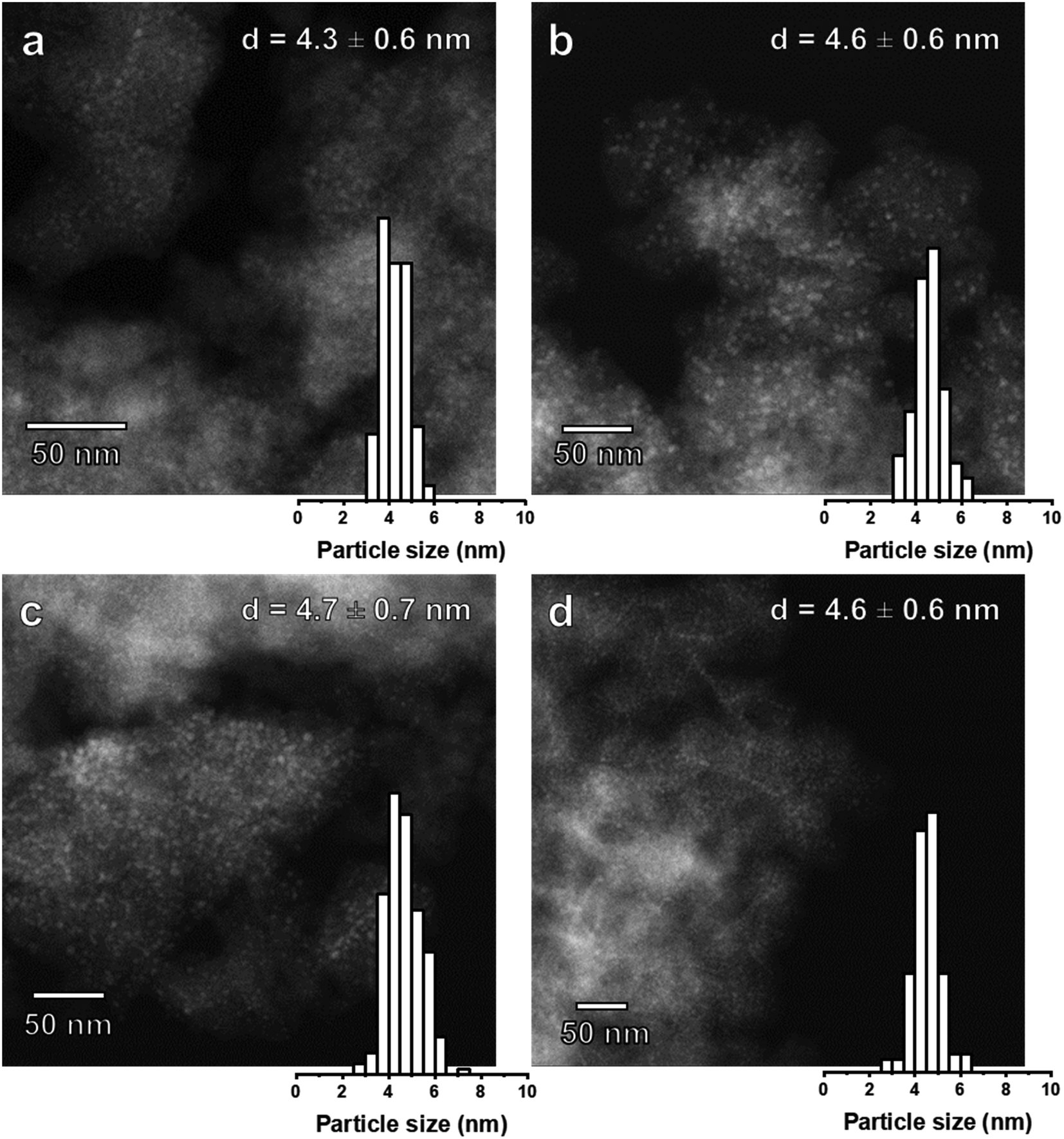 | ||
| Fig. 10 HAADF-STEM images and particle size distribution of (a) Ni(4.4)@SiO2 (b) Ni(5.0)@SiO2 (c) Ni(6.8)@SiO2 and (d) Ni(7.2)@SiO2 catalysts after reduction at 600 °C (50 nm scale bar). | ||
3.5 Catalytic performance in CO2 methanation: activity and stability
The catalytic activity of Ni(x)@SiO2 catalysts for CO2 methanation was examined between 200–400 °C in a high-throughput fixed-bed reactor at atmospheric pressure and using a stoichiometric H2/CO2 ratio of 4. Catalysts were reduced in situ at 600 °C prior to exposure to the reaction mixture. The stability of these materials was also part of our investigations, studying the conversion of the same materials at 350 °C for 70 h.All catalysts were active within the studied temperature range, showing a typical Arrhenius behavior of the conversion at low temperature and deviation from this trend due to the approach to equilibrium at higher temperature (Fig. 11a). No hydrocarbons other than CH4 were detected. Turnover frequencies (TOFs) normalized to surface Ni content were calculated under differential conditions (<10% conversion) at 250 °C (Table 4). No CO formation was observed under these conditions (Fig. 11b). The TOFs revealed that there was no significant difference in catalytic activity, which can be expected as the encapsulated catalysts are almost identical apart from their Ni content. These TOFs are comparable to those reported in literature for Ni/SiO2 systems.65,66 Identical apparent activation energies were also determined for encapsulated catalysts (∼75 kJ mol−1) which is in line with literature values.65–68 These results confirm that there are no adverse effects on the Ni activity by encapsulating the particles in mesoporous silica, and that the catalysts were free from mass transfer limitations.
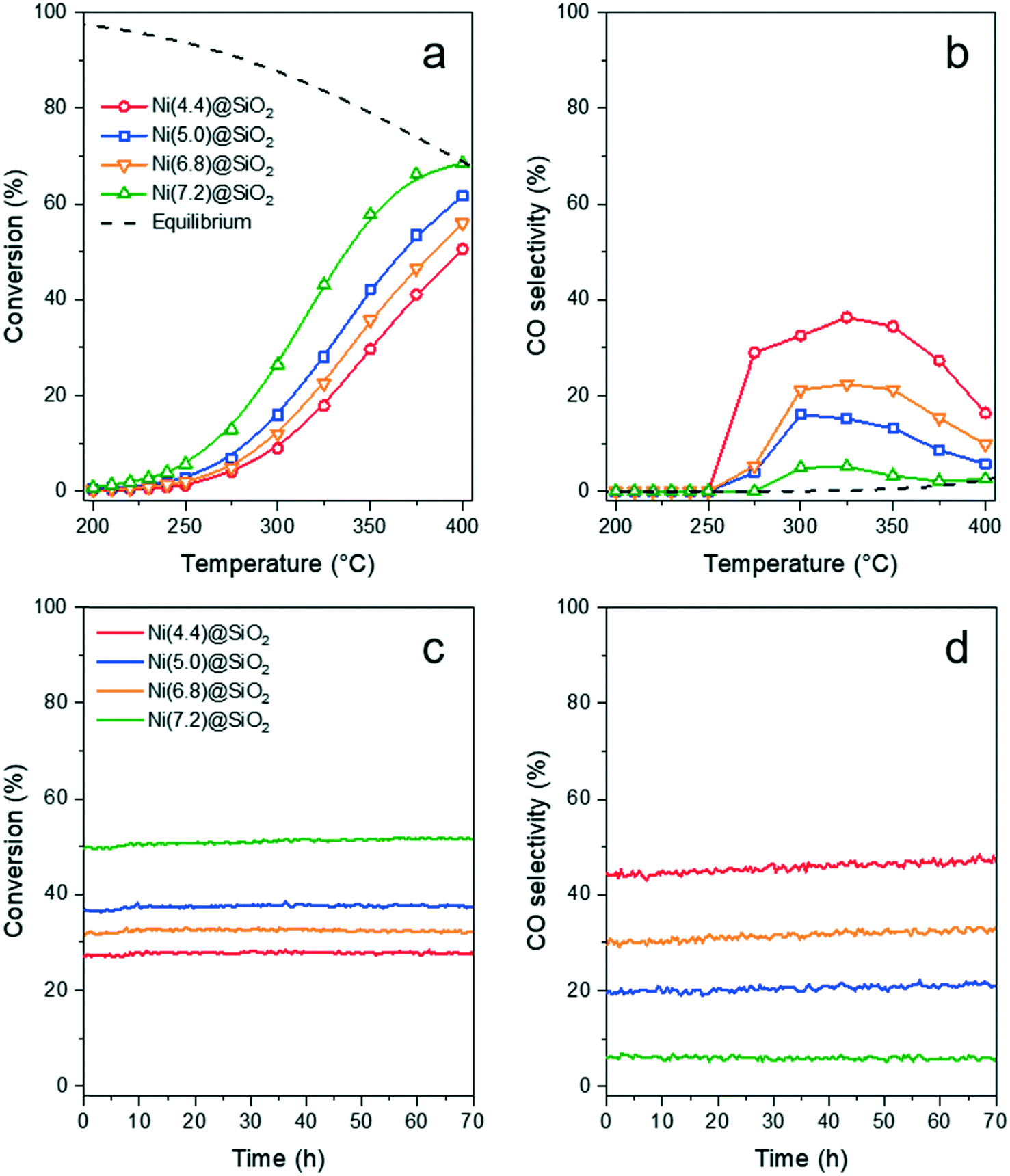 | ||
| Fig. 11 CO2 methanation (H2/CO2 = 4, 50 mL min−1) over Ni(x)@SiO2 showing the (a) CO2 conversion and (b) CO selectivity between 200–400 °C. Catalyst stability was studied at 350 °C and (c) CO2 conversion and (d) CO selectivity remained stable during 70 h. | ||
| Sample | Conversion (%) | CH4 selectivity (%) | TOFs (10−3 mol CH4 per mol surface Ni per s) | E appact (kJ mol−1) |
|---|---|---|---|---|
| Ni(4.4)@SiO2 | 1.3 | 100 | 7.0 (± 0.4) | 75 |
| Ni(5.0)@SiO2 | 2.9 | 100 | 5.7 (± 0.02) | 75 |
| Ni(6.8)@SiO2 | 2.0 | 100 | 5.7 (± 0.09) | 74 |
| Ni(7.2)@SiO2 | 5.7 | 100 | 6.7 (± 0.03) | 77 |
Similar conversion trends were observed during the stability study at 350 °C (Fig. 11c) in which all catalysts were found to be stable for 70 h. Catalysts with a lower Ni content exhibited higher CO selectivities. The catalyst with the lowest Ni content, i.e. Ni(4.4)@SiO2, had a CO selectivity of 43–47% during the entire study. In contrast the highest loaded catalyst, Ni(7.2)@SiO2, had a CO selectivity below 10% throughout the stability test (Fig. 11d). The slight increase in CO selectivity for Ni(4.4)@SiO2, Ni(5.0)@SiO2, and Ni(6.8)@SiO2 catalysts during the stability test may indicate that some of the particles on the external SiO2 surface sintered under reaction conditions. Earlier studies have shown that larger Ni particles have a higher selectivity towards CO.69
To verify whether Ni dispersion changed during the catalytic reaction, spent catalysts were analyzed with HAADF-STEM. Fig. 12 shows HAADF-STEM images of Ni(4.4)@SiO2 (2.4 wt% Ni) and Ni(7.2)@SiO2 (8.6 wt% Ni), i.e. the catalysts at the extreme ends of the initial colloidal particle size and metal loadings, after 70 h CO2 methanation. For Ni(4.4)@SiO2, evidence of particle aggregation was found, although there were clearly also particles that were identical to the initial particle size. This suggests that some particles were not encapsulated and their mobility under reaction conditions led to some sintering. In contrast, encapsulated NiNPs (Fig. 12a, circled) retained their original particle size. This was also observed for Ni(7.2)@SiO2 (Fig. 12b) and the remaining Ni(x)@SiO2 catalysts (see ESI†), which had a higher Ni loading and showed no evidence of particle aggregation. Moreover, we observed significant areas in Ni(4.4)@SiO2 that did not contain NiNPs. We anticipate therefore that with an encapsulation approach in which SiO2 is grown around the NiNPs, Ni catalysts with loadings significantly higher than 8 wt% should be attainable without nanoparticle sintering. Such an approach appears more promising than methods like impregnation or chemical vapor deposition in mesoporous silica or other zeotype materials, in which the possibility of Ni deposition outside of mesopores and cavities (i.e., on the external crystal surface) and Ni aggregation are more difficult to control.42,70,71 Across all samples, particle sizes remained essentially unchanged, with sintering attributed to unencapsulated nanoparticles.
 | ||
| Fig. 12 HAADF-STEM images of (a) Ni(4.4)@SiO2 and (b) Ni(7.2)@SiO2 catalysts after exposure to CO2 methanation conditions. | ||
4 Conclusions
Colloidal NiNPs were successfully synthesized and grown using a seed-mediated approach to give particle sizes between 3–8 nm. To the best of our knowledge, this is the first seed-mediated approach reported for colloidal Ni nanoparticle synthesis that controls particle sizes below 10 nm without employing P-ligands. In addition, these colloidal NiNPs were encapsulated in mesoporous SiO2 to yield active and highly stable methanation catalysts. Despite gaining control over the colloidal NiNP size, the Ni particle sizes were identical for all catalysts after calcination and reduction treatments. Ultimately, the silica pore sizes determined the final Ni particle size with the Ni redistributed throughout the mesopores, with initially larger particles becoming smaller. This rigid encapsulation ensured that the Ni did not sinter during methanation and should allow for Ni catalysts with high loadings to maintain their dispersion. We expect that this method may be further optimized by changing the silica templating agent to manipulate the pore sizes, thereby controlling the final Ni particle size to achieve catalysts tailored towards specific structure–sensitive reactions.Conflicts of interest
There are no conflicts of interest to declare.Acknowledgements
The authors thank NWO and BASF for a TA-CHIPP grant. The authors thank Charlotte Vogt (Utrecht University) for bright-field TEM measurements and Georgy Filonenko (TU Delft) for fruitful discussions. We thank Adelheid Elemans-Mehring (TU Eindhoven) for performing the elemental analysis.References
- C.-J. J. Jia and F. Schüth, Phys. Chem. Chem. Phys., 2011, 13, 2457–2487 RSC.
- M. Cargnello, Chem. Mater., 2019, 31, 576–596 CrossRef CAS.
- P. Sonström and M. Bäumer, Phys. Chem. Chem. Phys., 2011, 13, 19270 RSC.
- P. Losch, W. Huang, E. D. Goodman, C. J. Wrasman, A. Holm, A. R. Riscoe, J. A. Schwalbe and M. Cargnello, Nano Today, 2019, 24, 15–47 CrossRef CAS.
- R. A. Van Santen, Acc. Chem. Res., 2009, 42, 57–66 CrossRef CAS PubMed.
- G. L. Bezemer, J. H. Bitter, H. P. C. E. Kuipers, H. Oosterbeek, J. E. Holewijn, X. Xu, F. Kapteijn, A. J. Van Diilen and K. P. De Jong, J. Am. Chem. Soc., 2006, 128, 3956–3964 CrossRef CAS PubMed.
- M. P. Andersson, F. Abild-Pedersen, I. N. Remediakis, T. Bligaard, G. Jones, J. Engbæk, O. Lytken, S. Horch, J. H. Nielsen and J. Sehested, J. Catal., 2008, 255, 6–19 CrossRef CAS.
- C. Vogt, E. Groeneveld, G. Kamsma, M. Nachtegaal, L. Lu, C. J. Kiely, P. H. Berben, F. Meirer and B. M. Weckhuysen, Nat. Catal., 2018, 1, 127–134 CrossRef.
- J. Gao, Q. Liu, F. Gu, B. Liu, Z. Zhong and F. Su, RSC Adv., 2015, 5, 22759–22776 RSC.
- T. S. Rodrigues, A. G. M. da Silva and P. H. C. Camargo, J. Mater. Chem. A, 2019, 7, 5857–5874 RSC.
- P. Munnik, P. E. de Jongh and K. P. de Jong, Chem. Rev., 2015, 115, 6687–6718 CrossRef CAS PubMed.
- Z. Niu and Y. Li, Chem. Mater., 2014, 26, 72–83 CrossRef CAS.
- A. J. F. van Hoof, D. A. J. Michel-Ligthart, H. Friedrich and E. J. M. Hensen, ChemCatChem, 2017, 9, 1018–1024 CrossRef CAS.
- E. Zacharaki, P. Beato, R. R. Tiruvalam, K. J. Andersson, H. Fjellvåg and A. O. Sjåstad, Langmuir, 2017, 33, 9836–9843 CrossRef CAS PubMed.
- Y. Xia, K. D. Gilroy, H.-C. Peng and X. Xia, Angew. Chem., Int. Ed., 2017, 56, 60–95 CrossRef CAS PubMed.
- S. Mourdikoudis and L. M. Liz-Marzán, Chem. Mater., 2013, 25, 1465–1476 CrossRef CAS.
- H. T. Zhang, G. Wu, X. H. Chen and X. G. Qiu, Mater. Res. Bull., 2006, 41, 495–501 CrossRef CAS.
- Y. Chen, D.-L. Peng, D. Lin and X. Luo, Nanotechnology, 2007, 18, 505703 CrossRef.
- S. Carenco, C. Boissière, L. Nicole, C. Sanchez, P. Le Floch and N. Mézailles, Chem. Mater., 2010, 22, 1340–1349 CrossRef CAS.
- F. Davar, Z. Fereshteh and M. Salavati-Niasari, J. Alloys Compd., 2009, 476, 797–801 CrossRef CAS.
- E. J. Roberts, S. E. Habas, L. Wang, D. A. Ruddy, E. A. White, F. G. Baddour, M. B. Griffin, J. A. Schaidle, N. Malmstadt and R. L. Brutchey, ACS Sustainable Chem. Eng., 2017, 5, 632–639 CrossRef CAS.
- M. Shviro and D. Zitoun, RSC Adv., 2013, 3, 1380–1387 RSC.
- Y. Chen, X. Luo, H. She, G.-H. Yue and D.-L. Peng, J. Nanosci. Nanotechnol., 2009, 9, 5157–5163 CrossRef CAS.
- A. L. Abdelhady, M. A. Malik, P. O'Brien and F. Tuna, J. Phys. Chem. C, 2012, 116, 2253–2259 CrossRef CAS.
- D. S. Sidhaye, T. Bala, S. Srinath, H. Srikanth, P. Poddar, M. Sastry and B. L. V. Prasad, J. Phys. Chem. C, 2009, 113, 3426–3429 CrossRef CAS.
- H. Winnischofer, T. C. R. Rocha, W. C. Nunes, L. M. Socolovsky, M. Knobel and D. Zanchet, ACS Nano, 2008, 2, 1313–1319 CrossRef CAS PubMed.
- S. Carenco, D. Portehault, C. Boissière, N. Mézailles and C. Sanchez, Chem. Rev., 2013, 113, 7981–8065 CrossRef CAS.
- S. Carenco, Z. Liu and M. Salmeron, ChemCatChem, 2017, 9, 2318–2323 CrossRef CAS.
- L. M. Moreau, D.-H. Ha, C. R. Bealing, H. Zhang, R. G. Hennig and R. D. Robinson, Nano Lett., 2012, 12, 4530–4539 CrossRef CAS PubMed.
- R. Rinaldi, A. M. Porcari, T. C. R. Rocha, W. H. Cassinelli, R. U. Ribeiro, J. M. C. Bueno and D. Zanchet, J. Mol. Catal. A: Chem., 2009, 301, 11–17 CrossRef CAS.
- V. Iablokov, S. K. Beaumont, S. Alayoglu, V. V. Pushkarev, C. Specht, J. Gao, A. P. Alivisatos, N. Kruse and G. A. Somorjai, Nano Lett., 2012, 12, 3091–3096 CrossRef CAS PubMed.
- Y. Hou and S. Gao, J. Mater. Chem., 2003, 13, 1510–1512 RSC.
- H. Li, H. Lin, Y. Hu, H. Li, P. Li and X. Zhou, J. Mater. Chem., 2011, 21, 18447–18453 RSC.
- D.-H. Chen and C.-H. Hsieh, J. Mater. Chem., 2002, 12, 2412–2415 RSC.
- Y. Jeon, G. H. Lee, J. Park, B. Kim and Y. Chang, J. Phys. Chem. B, 2005, 109, 12257–12260 CrossRef CAS.
- R. Eluri and B. Paul, J. Nanopart. Res., 2012, 14, 800 CrossRef.
- V. Tzitzios, G. Basina, M. Gjoka, V. Alexandrakis, V. Georgakilas, D. Niarchos, N. Boukos and D. Petridis, Nanotechnology, 2006, 17, 3750–3755 CrossRef CAS.
- O. Metin, V. Mazumder, S. Özkar and S. Sun, J. Am. Chem. Soc., 2010, 132, 1468–1469 CrossRef CAS.
- Ö. Metin, S. Özkar and S. Sun, Nano Res., 2010, 3, 676–684 CrossRef.
- Y. Li, J. Wen, A. M. Ali, M. Duan, W. Zhu, H. Zhang, C. Chen and Y. Li, Chem. Commun., 2018, 54, 6364–6367 RSC.
- D. Laprune, A. Tuel, D. Farrusseng and F. C. Meunier, ChemCatChem, 2017, 9, 2297–2307 CrossRef CAS.
- F. Goodarzi, L. Kang, F. R. Wang, F. Joensen, S. Kegnaes and J. Mielby, ChemCatChem, 2018, 10, 1566–1570 CrossRef CAS.
- G. H. Layan Savithra, E. Muthuswamy, R. H. Bowker, B. A. Carrillo, M. E. Bussell and S. L. Brock, Chem. Mater., 2013, 25, 825–833 CrossRef CAS.
- S. H. Joo, J. Y. Park, C.-K. Tsung, Y. Yamada, P. Yang and G. A. Somorjai, Nat. Mater., 2009, 8, 126–131 CrossRef CAS PubMed.
- H. Song, R. M. Rioux, J. D. Hoefelmeyer, R. Komor, K. Niesz, M. Grass, P. Yang and G. A. Somorjai, J. Am. Chem. Soc., 2006, 128, 3027–3037 CrossRef CAS PubMed.
- A. H. Habibi, R. E. Hayes and N. Semagina, Catal. Sci. Technol., 2018, 8, 798–805 RSC.
- G. Collins, K. Rahme, J. O'Connell and J. D. Holmes, Catal. Sci. Technol., 2016, 6, 7212–7219 RSC.
- M. A. Lucchini, A. Testino, A. Kambolis, C. Proff and C. Ludwig, Appl. Catal., B, 2016, 182, 94–101 CrossRef CAS.
- J. Zhang and F. Li, Appl. Catal., B, 2015, 176–177, 513–521 CrossRef CAS.
- J. Pu, K. Nishikado, N. Wang, T. T. Nguyen, T. Maki and E. W. Qian, Appl. Catal., B, 2018, 224, 69–79 CrossRef CAS.
- Y. Koltypin, A. Fernandez, T. C. Rojas, J. Campora, P. Palma, R. Prozorov and A. Gedanken, Chem. Mater., 1999, 11, 1331–1335 CrossRef CAS.
- M. Feygenson, A. Kou, L. E. Kreno, A. L. Tiano, J. M. Patete, F. Zhang, M. S. Kim, V. Solovyov, S. S. Wong and M. C. Aronson, Phys. Rev. B: Condens. Matter Mater. Phys., 2010, 81, 014420 CrossRef.
- L. He, J. Magn. Magn. Mater., 2010, 322, 1991–1993 CrossRef CAS.
- Y. Goto, K. Taniguchi, T. Omata, S. Otsuka-Yao-Matsuo, N. Ohashi, S. Ueda, H. Yoshikawa, Y. Yamashita, H. Oohashi and K. Kobayashi, Chem. Mater., 2008, 20, 4156–4160 CrossRef CAS.
- Z. L. Schaefer, K. M. Weeber, R. Misra, P. Schiffer and R. E. Schaak, Chem. Mater., 2011, 23, 2475–2480 CrossRef CAS.
- P. Hooker, B. J. Tan, K. J. Klabunde and S. Suib, Chem. Mater., 1991, 3, 947–952 CrossRef CAS.
- Y. Leng, Y. Liu, X. Song and X. Li, J. Nanosci. Nanotechnol., 2008, 8, 4477–4481 CrossRef CAS.
- B. C. Bayer, D. A. Bosworth, F. B. Michaelis, R. Blume, G. Habler, R. Abart, R. S. Weatherup, P. R. Kidambi, J. J. Baumberg, A. Knop-Gericke, R. Schloegl, C. Baehtz, Z. H. Barber, J. C. Meyer and S. Hofmann, J. Phys. Chem. C, 2016, 120, 22571–22584 CrossRef CAS PubMed.
- Y. Leng, L. Xie, F. Liao, J. Zheng and X. Li, Thermochim. Acta, 2008, 473, 14–18 CrossRef CAS.
- J. Park, E. Kang, S. U. Son, H. M. Park, M. K. Lee, J. Kim, K. W. Kim, H.-J. Noh, J.-H. Park, C. J. Bae, J.-G. Park and T. Hyeon, Adv. Mater., 2005, 17, 429–434 CrossRef CAS.
- V. K. LaMer and R. H. Dinegar, J. Am. Chem. Soc., 1950, 72, 4847–4854 CrossRef CAS.
- J. Polte, CrystEngComm, 2015, 17, 6809–6830 RSC.
- P. Burattin, M. Che and C. Louis, J. Phys. Chem. B, 1997, 101, 7060–7074 CrossRef CAS.
- J. C. Park, H. J. Lee, J. U. Bang, K. H. Park and H. Song, Chem. Commun., 2009, 7345–7347 RSC.
- C. K. Vance and C. H. Bartholomew, Appl. Catal., 1983, 7, 169–177 CrossRef CAS.
- C. H. Batholomew and C. K. Vance, J. Catal., 1985, 91, 78–84 CrossRef.
- G. D. Weatherbee and C. H. Bartholomew, J. Catal., 1981, 68, 67–76 CrossRef CAS.
- M. A. A. Aziz, A. A. Jalil, S. Triwahyono, R. R. Mukti, Y. H. Taufiq-Yap and M. R. Sazegar, Appl. Catal., B, 2014, 147, 359–368 CrossRef CAS.
- G. Garbarino, P. Riani, L. Magistri and G. Busca, Int. J. Hydrogen Energy, 2014, 39, 11557–11565 CrossRef CAS.
- M. C. Bacariza, I. Graça, S. S. Bebiano, J. M. Lopes and C. Henriques, Chem. Eng. Sci., 2018, 175, 72–83 CrossRef CAS.
- J. R. A. Sietsma, J. D. Meeldijk, M. Versluijs-Helder, A. Broersma, A. J. van Dillen, P. E. de Jongh and K. P. de Jong, Chem. Mater., 2008, 20, 2921–2931 CrossRef CAS.
Footnotes |
| † Electronic supplementary information (ESI) available: Synthesis procedures and additional material characterization including TEM, XPS (quantification and sputtering results), TGA profiles, N2 physisorption isotherms, and HAADF-STEM images. See DOI: 10.1039/c9cy00532c |
| ‡ Present address: Inorganic Systems Engineering group, Department of Chemical Engineering, Delft University of Technology, Van der Maasweg 9, 2629 HZ, Delft, The Netherlands. |
| This journal is © The Royal Society of Chemistry 2019 |