 Open Access Article
Tailoring the mechanical properties of polymer nanocomposites via interfacial engineering†
Naishen
Gao
a,
Guanyi
Hou
a,
Jun
Liu
 *abcd,
Jianxiang
Shen
e,
Yangyang
Gao
 a,
Alexey V.
Lyulin
 *f and
Liqun
Zhang
 abcdg
abcdg
aKey Laboratory of Beijing City on Preparation and Processing of Novel Polymer Materials, Beijing University of Chemical Technology, People's Republic of China
bBeijing Engineering Research Center of Advanced Elastomers, Beijing University of Chemical Technology, People's Republic of China. E-mail: liujun@mail.buct.edu.cn
cEngineering Research Center of Elastomer Materials on Energy Conservation and Resources, Beijing University of Chemical Technology, People's Republic of China
dBeijing Advanced Innovation Center for Soft Matter Science and Engineering, Beijing University of Chemical Technology, 100029 Beijing, People's Republic of China
eCollege of Materials and Textile Engineering, Jiaxing University, Jiaxing 314001, People's Republic of China
fTheory of Polymers and Soft Matter, Department of Applied Physics Technische Universiteit Eindhoven, 5600 MB Eindhoven, The Netherlands. E-mail: a.v.lyulin@tue.nl
gState Key Laboratory of Organic–Inorganic Composites, Beijing University of Chemical Technology, 100029 Beijing, People's Republic of China
First published on 7th August 2019
Abstract
The improvement of mechanical properties of polymer nanocomposites (PNCs) has been studied for many years, with the main focus on the structure of the nanofillers. Much less effort has been devoted to unraveling the factors controlling the structure of the grafted chains. Herein, through coarse-grained molecular-dynamics simulations, we have successfully fabricated an ideal, mechanically-interlocked composite structure composed of end-functionalized chains grafted to the nanoparticle surface forming rings and making the matrix chains thread through these rings. Depending on the details of the grafting, the reinforcement effect can be remarkable, improving the tensile stress of the system significantly up to 700%. Meanwhile, anisotropy of the system's mechanical response is also observed. Furthermore, the influence of the grafted chain distribution on the mechanical properties of the system has been investigated as well. We observe that the mechanical properties of the system are closely related to the total number of the beads in the grafted chains or the synergistic effect between the length and density of the grafted chains leads to no significant difference in the performance of systems. At constant grafting density, the mechanical properties of the systems correlate negatively to the grafted chain length. In general, our study should help to design and fabricate high-performance PNCs with excellent mechanical properties.
I. Introduction
Polymer nanocomposites (PNCs) have become a prominent area of current research and development. The addition of hard nanoparticles (NPs) to a polymer matrix leads to a significant improvement of the mechanical, electrical and optical properties of PNCs,1–6 signaling that PNCs have high potential value in various applications such as display panels, photonic crystals and memory devices with magnetic nanocomposite multilayers.7–9 Over the past few decades, many theoretical and experimental studies have revealed that the microscopic morphology of the constituent NPs strongly influences the macroscopic properties of PNCs.10–14 Shen et al.15,16 investigated the strain-induced non-linear mechanical behavior of a polymer filled with spherical and grafted NPs, and showed that there exist an optimal grafting density and grafted chain length that help to improve the dispersion of the grafted NPs. Moreover, Liu et al.17 studied the effect of the filler volume fraction (FVF) and polymer–filler interaction parameters on the mechanical response of the reinforced elastomers, and identified the existence of an optimal FVF for the mechanical reinforcement in the presence of strong polymer–filler interactions. Note that the structure of the polymer chains could have a pronounced effect on the performance of PNCs, by mainly controlling the dispersion state or the spatial distribution of NPs in the polymer matrix.18–22 However, it is extremely difficult to produce well-dispersed states of immiscible inorganic NPs in a polymer matrix. At the same time, a good NP dispersion has been shown23 to be responsible for good mechanical reinforcement. Various strategies have been suggested for the control of the spatial distribution of NPs, invoking their surface modification such as by adding surfactants (cationic, anionic or nonionic),24–26 inorganic surface modification,27,28 adsorbent modification,29,30 and using grafted polymer chains.29,31 The last method is rather popular,32–34 and in this case, the grafted chains are similar to an amphiphilic material, promoting the compatibility of NPs with the polymer matrix. In this case, the interfacial interactions can be tuned by controlling the grafting density, the grafted chain length, the polymer matrix chain length and the diameter of NPs.For low grafting densities, the direct aggregation of NPs cannot be fully shielded; in this case, the NPs with uniformly grafted polymer chains will self-assemble into a variety of anisotropic structures18,35–38 due to the symmetry breaking of the NP–NP interactions. At sufficiently high grafting density, the grafted polymer chains form “chain brush” conformations, which induce material stretching. Because of the increase of the excluded volume of the grafted NPs, and the enhanced interfacial interaction strength between the grafted chains and the polymer matrix chains, the NPs tend to be dispersed better in the polymer matrix.39–42 Besides, the grafted chain length, the strength of the interactions between the grafted chains and the matrix chains, and the effect of the block-copolymer nature of the grafted chains on the dispersion of NPs in the polymer matrix have also been studied systematically.43,44
Furthermore, the addition of grafted NPs is also significant for the mechanical properties of the systems. It has been observed that for many PNCs filled with grafted inorganic NPs, such as carbon black or precipitated silica, the Young's modulus and the tensile strength can both decrease by about 40%,45 remain almost unchanged46 or increase by about 15%,47 depending on whether the interfacial compatibility between the grafted “brushes” and the polymer matrix is bad, intermediate or good, respectively. However, strong interactions between the grafted “brushes” and the polymer matrix always result in an improvement of the mechanical properties.43 Besides, Goyal et al.48 employed coarse-grained dynamic simulations to investigate the shear thinning of PNCs filled with grafted NPs, as well as the Brownian stress under uniaxial deformation, suggesting that longer grafted chains could lead to a better reinforcement. The complex viscosity and the storage modulus of the materials increase due to the formation of additional entanglements between the grafted chains and the matrix chains.49
The effect of the self-assembled structures of PNCs on the macroscopic properties is important as well. By employing coarse-grained Monte Carlo simulations, Kumar et al.35,50 investigated systematically the different self-assembled NP structures with uniformly grafted chains at low grafting densities. They also studied experimentally the corresponding mechanical properties, and observed that the existing sheet structure enhanced the mechanical properties of the PNCs most prominently. Similar results were also obtained by Wang et al.51via self-assembly of polymer-grafted NPs. Using the mesoscale self-consistent field theory and density functional theory approach, the self-assembly of the polymer-grafted NPs was also investigated by Ginzburg,52 and similar structures were observed.
In spite of a rather large amount of previous research on the microstructures and the macroscopic properties of PNCs, their mechanical properties still cannot meet the necessary requirements. In particular, mechanical reinforcement is still a great challenge. Recently, Lopez-Moreno et al.53,54 studied the reinforcement of polymers by using mechanically interlocked derivatives of single-walled carbon nanotubes, formed by threading the carbon nanotubes through the polymer macrocycles. The improvements of both the Young's modulus and the tensile strength of up to 200% were observed for the polystyrene–nanotube samples with loadings of just 0.01 wt%, signaling that the mechanical bond imparts distinctive advantageous properties to the carbon nanotube derivatives as polymer fillers. The results show that mechanical interlocking is a strategy that can optimize the mechanical performance of polymer composites. Even more so, using bimodal distributed grafted chains is known to be an effective strategy to improve the distribution of NPs and to achieve a good NP dispersion. Schadler et al.6,55,56 have shown that particles with mono-modal grafted chains easily aggregate, but, fortunately, by mixing sparsely grafted long chains with short grafted chains, the interparticle attraction is screened enough to achieve a good dispersion of NPs, which greatly improves the thermomechanical properties of the nanocomposites. Meanwhile, Shi57 pointed out that rather short grafted chains can not only shield the NP surface from the polymer matrix, but also force the long grafted chains to elongate further into the polymer matrix.
In this study, by using coarse-grained molecular-dynamics simulations (CGMDS),58 we investigate the relationship between the structure and the mechanical properties of a mechanically interlocked polymer system via grafting the polymer chains to the NP surface with both ends, and making ring structures. Ungrafted matrix chains have to thread through these grafted rings, and entangle with them. We study the effects of the stiffness of the matrix chains and the ring shape of the grafted chains on the formation of this mechanically interlocked structure. We also simulate and analyze the influence of the bimodal distribution of the grafted polymers on the composite mechanical properties, in the hope of providing scientific guidance for the design and fabrication of PNCs with remarkable and adjustable mechanical properties tailored for practical applications.
II. Model and simulation method
We adopted the classical CGMDS to study the mechanical properties of the interlocked and bimodal polymer-grafted nanocomposites. The polymer chains were represented by the bead-spring model developed by Kremer and Grest.59 The monomers were lumped together into spherical beads, and the beads were connected by elastic springs.60 Here, since it is not our target to study a specific polymer, we use reduced units, in which ε is the LJ energy parameter, and m and σ are the mass and diameter of the monomer, respectively. This means that all calculated quantities are dimensionless. One polymer bead with a diameter of σ (using the Lennard-Jones length unit) corresponds to 3–6 monomers in a realistic polymer chain such as, for example, polybutadiene.61–63 A simulated matrix polymer chain consisted of Lm = 100 beads with mass m and diameter σ. The number of the matrix polymer chains is Nm = 100 in both the mechanically interlocked and bimodal systems, as explained later. The bead size of the grafted chains is equal to that in the matrix chains. Nevertheless, we stress that in reality, the grafted polymers can be chemically different from the matrix.The nanoparticles were represented by beads with a diameter of 4σ and a mass of 64m. Two systems, one with the mechanically interlocked structure and another one with NPs modified by the bimodal distributed grafted polymer chains, have been simulated with 30 NPs. In the two systems, the grafted chains were randomly distributed on the surface of NPs, using the chemical bond between the head atom of the grafted chain and the NP. The exact position of the contact can slip on the NP surface during the equilibration and stretching process. The total number of grafted polymer chains is characterized by the grafting density Σ as
 | (1) |
The non-bonded interactions between all the beads, including polymer–polymer, polymer–nanoparticle, and nanoparticle–nanoparticle, were described by the truncated and shifted Lennard-Jones (LJ) potential
 | (2) |
The bond interactions between the adjacent beads were modeled by a harmonic potential,64
 | (3) |
The bending angle of the polymer chain between three consecutive beads was modeled by a harmonic potential,69
 | (4) |
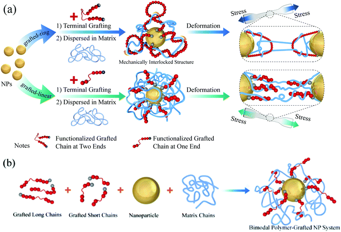
In the present simulations of the mechanically interlocked system (the first simulated model), the grafted polymer chains were made to be bi-functional at both ends. To create the grafted ring structure, it was necessary to graft the two ends of a grafted chain onto one NP, so that the grafted rings and the remaining matrix chains can form the mechanically interlocked structure, the grafted-ring system (GR system), easily, as shown in Fig. 1(a). In the presented simulations, we have fixed the grafting density to Σ = 0.2, and the length of all the grafted chains was equal to Lg = 25. Initially, the simulated box contained only three NPs. This initial box was replicated in both X and Y directions, resulting in a 10 times larger system.
The challenge at this stage was to make a mechanically interlocked structure, and there were two key points in the system construction process that can be mentioned: one has to let the matrix chains thread through the ring, and, after that, one has to lock up the mechanically interlocked structure. To achieve these two purposes, the whole equilibration process was carried out in two steps. During the first equilibration step, the matrix–matrix and the graft–graft LJ interactions were set to be repulsive. This helps to have both the matrix chains and the grafted rings stretched enough, which is beneficial for the matrix chains to thread through the grafted rings. In the second equilibration step, both matrix–matrix and graft–graft interactions were set to be attractive, which is beneficial to lock up the already interlocked structure. The details of all the LJ interaction parameters during the equilibration are listed in Table 1. As our main goal is to provide some modelling insights into the influence of the mechanically interlocked structure on the mechanical properties of PNCs, we compared the tensile properties of the simulated grafted-ring composite system (GR system) with those of the grafted-linear composite system (GL system), as shown in Fig. 1(a), under the same other conditions.
| Interacting beads | First step | Second step | ||
|---|---|---|---|---|
| ε | r cutoff | ε | r cutoff | |
| Matrix–matrix | 1.0 | 1.12 | 1.0 | 2.24 |
| Matrix–graft | 1.0 | 2.5 | 1.0 | 2.5 |
| Graft–graft | 1.0 | 1.12 | 1.0 | 2.5 |
| Matrix–NP | 1.0 | 2.5 | 1.0 | 2.5 |
| Graft–NP | 1.0 | 1.12 | 1.0 | 1.12 |
| NP–NP | 1.0 | 1.12 | 1.0 | 1.12 |
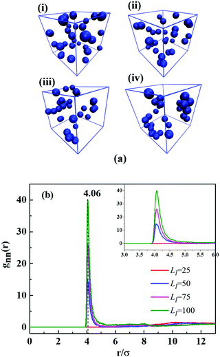
In the second simulated model, the grafted polymer chains of the same structure (functional at only one end), but with different length, were grafted onto each NP. In what follows, this system will be referred to as a “Bimodal polymer-grafted NP”. The length of the grafted short chains was fixed to Ls = 25, and the grafted long chain length Ll was varied from Ll = 25 to Ll = 100. Each grafted chain had only one grafting site at the end that would be bonded to the NP surface during the grafting process, and the formation of the ring structure was prevented. Thirty of such bimodal polymer-grafted NPs were then mixed homogeneously with the matrix chains (Lm = 100 and Nm = 100), as shown schematically in Fig. 1(b).
The fraction of the grafted chains (Cg) was determined as:
 | (5) |
| System | N l/Ns | L l/Ls | n g/nm | C g |
|---|---|---|---|---|
| a N l – number of grafted long chains per NP, Ns – number of grafted short chains per NP, Ll – length of the grafted long chains, Ls – length of the grafted short chains, ng – total number of grafted beads, nm – total number of matrix beads, Cg – the fraction of grafted chains. | ||||
| 1 | 10/10 | 25/25 | 15![[thin space (1/6-em)]](https://www.rsc.org/images/entities/char_2009.gif) 000/10 000/10![[thin space (1/6-em)]](https://www.rsc.org/images/entities/char_2009.gif) 000 000 |
0.6 |
| 2 | 7/6 | 50/25 | 15![[thin space (1/6-em)]](https://www.rsc.org/images/entities/char_2009.gif) 000/10 000/10![[thin space (1/6-em)]](https://www.rsc.org/images/entities/char_2009.gif) 000 000 |
0.6 |
| 3 | 5/5 | 75/25 | 15![[thin space (1/6-em)]](https://www.rsc.org/images/entities/char_2009.gif) 000/10 000/10![[thin space (1/6-em)]](https://www.rsc.org/images/entities/char_2009.gif) 000 000 |
0.6 |
| 4 | 4/4 | 100/25 | 15![[thin space (1/6-em)]](https://www.rsc.org/images/entities/char_2009.gif) 000/10 000/10![[thin space (1/6-em)]](https://www.rsc.org/images/entities/char_2009.gif) 000 000 |
0.6 |
| System | N l/Ns | L l/Ls | n g/nm | C g |
|---|---|---|---|---|
| a N l – number of grafted long chains per NP, Ns – number of grafted short chains per NP, Ll – length of the grafted long chains, Ls – length of the grafted short chains, ng – total number of grafted beads, nm – total number of matrix beads, and Cg – the fraction of grafted chains. | ||||
| 1 | 10/10 | 25/25 | 15![[thin space (1/6-em)]](https://www.rsc.org/images/entities/char_2009.gif) 000/10 000/10![[thin space (1/6-em)]](https://www.rsc.org/images/entities/char_2009.gif) 000 000 |
0.6 |
| 2 | 10/10 | 40/25 | 19![[thin space (1/6-em)]](https://www.rsc.org/images/entities/char_2009.gif) 500/10 500/10![[thin space (1/6-em)]](https://www.rsc.org/images/entities/char_2009.gif) 000 000 |
0.66 |
| 3 | 10/10 | 50/25 | 22![[thin space (1/6-em)]](https://www.rsc.org/images/entities/char_2009.gif) 500/10 500/10![[thin space (1/6-em)]](https://www.rsc.org/images/entities/char_2009.gif) 000 000 |
0.69 |
| 4 | 10/10 | 75/25 | 30![[thin space (1/6-em)]](https://www.rsc.org/images/entities/char_2009.gif) 000/10 000/10![[thin space (1/6-em)]](https://www.rsc.org/images/entities/char_2009.gif) 000 000 |
0.75 |
| 5 | 10/10 | 100/25 | 37![[thin space (1/6-em)]](https://www.rsc.org/images/entities/char_2009.gif) 500/10 500/10![[thin space (1/6-em)]](https://www.rsc.org/images/entities/char_2009.gif) 000 000 |
0.79 |
In the simulations with “Bimodal polymer-grafted NP” systems, both grafted chains and the matrix chains were flexible and corresponded to chemically different polymers. We, nevertheless, set the interaction energy parameter ε between beads corresponding to matrix–matrix εmm, grafted–grafted εgg, matrix–grafted εmg, matrix–NP εmn, grafted–NP εgn, and NP–NP εnn interactions all equal to 1.0. To avoid agglomeration of the grafted chains, repulsive interactions between the grafted–grafted polymer chains were introduced by setting rcutoff = 21/6σ. The attractive interactions between the matrix–grafted chains were modelled by setting rcutoff = 2.5σ to promote entanglements. Weak attractions between the matrix–matrix chains were introduced by setting rcutoff = 2 × 21/6σ, whereas the NP–NP parameter was set to be rcutoff = 21/6σ to help dispersion.
The simulations were started from a non-overlapped configuration of all matrix chains and polymer-grafted NPs in a large simulation box. The NPT and NVT ensembles were adopted, where the temperature was fixed at T* = 1.0, well above the glass-transition temperature for all the simulated systems. The pressure was set at P* = 1.0. The Nose–Hoover thermostat and barostat were used for temperature and pressure coupling. Periodic boundary conditions were applied in all three directions. The equations of motion were integrated using the velocity-Verlet algorithm with a time step Δt = 0.001τ, where τ is the LJ time unit  . The equilibration process was performed over a long time, for more than 1 × 10⁷ time steps for each system, to ensure that each polymer chain had moved at least 2Rg, where Rg is the corresponding root-mean-square radius of gyration.
After sufficient equilibration, the uniaxial tensile deformation was performed to obtain the stress–strain characteristics, similar to the approach utilized in our previous studies.73,74 The box length in the X direction was increased at a constant engineering strain rate, while the box lengths in the Y and Z directions were reduced simultaneously so as to maintain constant box volume. The strain rate was specified as  . The average stress σ in the X direction was obtained from the deviatoric part of the stress tensor σ = (1 + μ)(−PXX + P) ≈ 3(−PXX + P)/2, where
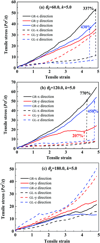
  was the hydrostatic pressure, taking stretching in the X direction as an example. The parameter μ stands for the Poisson's ratio, which was equal to 0.5 in the present simulations. Here, we conducted uniaxial tensile deformation in the X, Y and Z directions for mechanically interlocked systems, respectively, to characterize the mechanical anisotropy. Although the anisotropy of mechanical properties has been observed for even larger simulated samples, polymer systems of much larger size are required to make definite predictions about the mechanical anisotropy on the macroscopic scale. However, since the grafted chains and the matrix chains are both flexible, the system has an isotropic stress–strain behavior, which has been confirmed. Only the uniaxial tensile deformation in the X direction was performed for the bimodal polymer-grafted NP systems.
All the production runs were carried out by using the large-scale atomic/molecular massively parallel simulator (LAMMPS) software developed by Sandia National Laboratories.75 More simulation details can be found in our previous publications.15,76
III. Results and discussion
3.1 Mechanically interlocked system
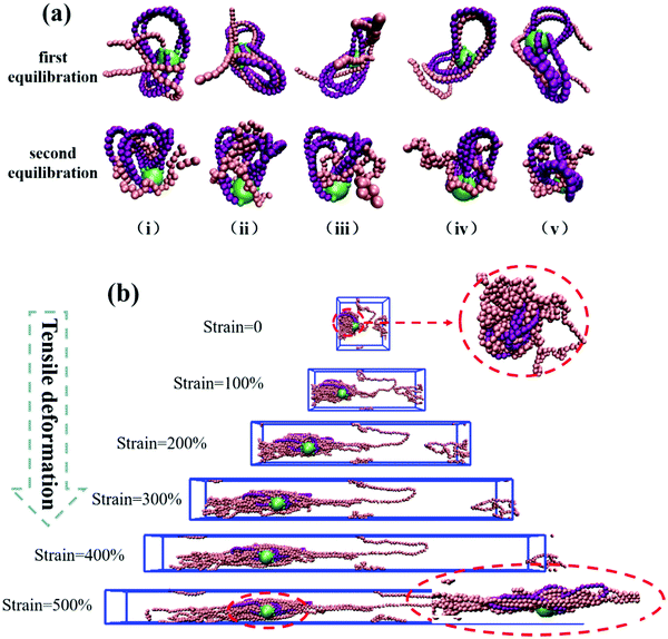
To understand the reason for the significant enhancement of the mechanical properties, we probe the microscopic morphology of the system. Taking k = 10.0 as an example, the typical snapshots of each step are shown in Fig. 3(a), highlighting one NP, its grafted rings, and five matrix chains entangled with the grafted rings. After the first step of equilibration, the matrix chains are arranged along the contour of the rings due to the attraction interactions. Moreover, penetration, or threading of the matrix chains into the grafted rings, is also observed. A slight agglomeration of the matrix chains occurs after the second step of equilibration, but, importantly, the threading of the matrix chains through the rings is not affected. From the analysis of the snapshots, we conclude that the desired mechanically interlocked structure is formed.
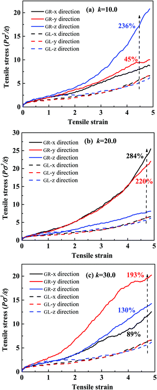
Next, we study the morphological evolution of the system during the uniaxial deformation (the Z direction was chosen), and the snapshots are presented in Fig. 3(b). For clarity, only one grafted-ring NP and five typical matrix chains are shown. We see that the conformation of the polymer chains in the deformation direction becomes extended, while in the X and Y directions, the conformations become significantly folded. Surprisingly, the matrix chains and the grafted rings are still entangled very tightly at an extremely large strain of 500%, which can explain the significant stress increase in the deformation direction. Some matrix chains do not entangle so tightly, and they tend to slip out of the rings during the stretching process, causing non-uniformity of the chain elongation and anisotropic stress–strain behavior, as clearly seen in Fig. 2.
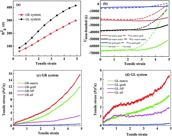
In addition to these intuitive snapshots reflecting the microscopic structure, there are other characterization methods that can be used to explain the microscopic mechanism for the mechanical enhancement. There is no doubt that the existence of a mechanically interlocked structure will inevitably promote the entanglement and agglomeration of polymer chains, which can be reflected by the mean-square radius of gyration (Rg2). By comparing Rg2 of the matrix chains in the GR system and GL system during the uniaxial deformation, shown in Fig. 4(a), we observe that Rg2 of the matrix chains in the GR system is lower than in the GL system, indicating that the matrix chains in the GR system are more agglomerated. Since the agglomeration of polymer chains may affect the interaction of the system, the non-bonded interaction energy (Unon-bonded) was characterized for different bead pairs of the GR system and GL system as a function of the tensile strain. It is important to note that the smaller (negative) the non-bonded interaction energy, the stronger the interactions between the corresponding parts. Obviously, as can be seen in Fig. 4(b), the strength of the non-bonded interactions of matrix–graft and matrix–matrix in the GL system decrease sharply after 300% strain, resulting in a dramatic total non-bonded interaction decrease. The non-bonded interactions of matrix–graft and matrix–matrix in the GR system change very little during the whole deformation process, indicating that the mechanically interlocked structure not only effectively enhances the interfacial interaction, but also promotes the entanglement between the matrix chains, thereby improving its mechanical properties.
What's more, to provide further understanding on the stress–strain behavior, we quantitatively calculate the distribution of different components on the total tensile stress in the GR system and the GL system, as shown in Fig. 4(c and d). The red curve represents the total tensile stress. The green, magenta and blue curves represent the stress component of the polymer matrix, grafted chains and NPs, respectively. By analyzing Fig. 4(c and d), it is clear that the mechanically interlocked structure can significantly enhance the mechanical properties of a system mainly by increasing the stress of the matrix chains during the stretching process, caused by the entanglement of matrix–matrix and matrix–graft.
3.2 Bimodal polymer-grafted NP system
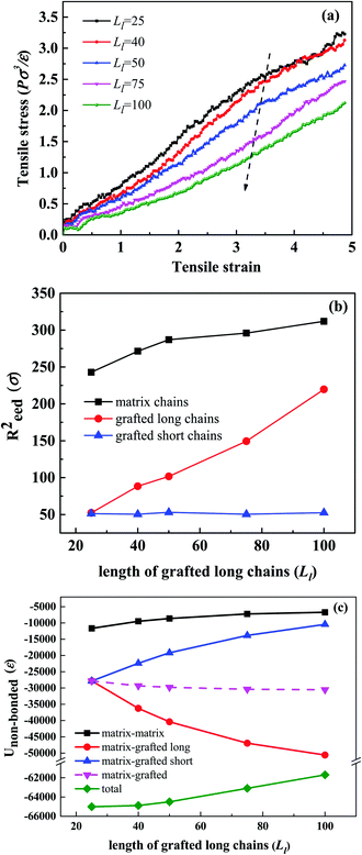
We have investigated the effect of Ll on the mechanical properties, and a uniaxial tension in the X-direction was applied. The tensile stress–strain behavior and the bond orientation during the uniaxial tensile deformation are shown in Fig. 7(a) and Fig. S4 (ESI†). We use the second-order Legendre polynomials, 〈P2(cos![[thin space (1/6-em)]](https://www.rsc.org/images/entities/char_2009.gif) θ)〉, to express the bond orientation. This function describes the average of the θ angle between a given bond vector and the reference (stretching) direction,
θ)〉, to express the bond orientation. This function describes the average of the θ angle between a given bond vector and the reference (stretching) direction,
〈P2(cos![[thin space (1/6-em)]](https://www.rsc.org/images/entities/char_2009.gif) θ)〉 = (3〈cos2 θ)〉 = (3〈cos2![[thin space (1/6-em)]](https://www.rsc.org/images/entities/char_2009.gif) θ〉)/2 θ〉)/2 | (6) |
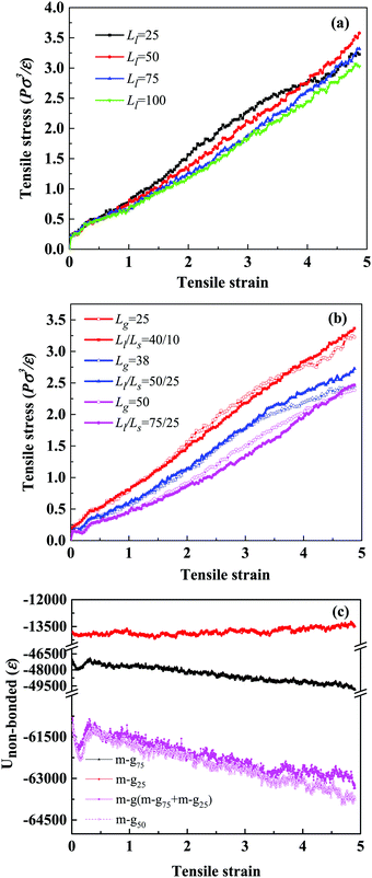
The values of 〈P2(cos![[thin space (1/6-em)]](https://www.rsc.org/images/entities/char_2009.gif) θ)〉 range from −0.5 to 1; −0.5, 1 and 0 indicate a perfect orientation perpendicular to the reference direction, parallel to the reference direction, or randomly oriented, respectively. Fig. 7(a) shows that the tensile stress curves are strikingly similar for different values of Ll. In Fig. S4 (ESI†), we observe that during the uniaxial deformation, the bond orientations of matrix chains, grafted long chains and grafted short chains are almost identical, which can explain the similarity of the stress–strain response. Therefore, we think that the mechanical properties of the systems are closely related to ng.
θ)〉 range from −0.5 to 1; −0.5, 1 and 0 indicate a perfect orientation perpendicular to the reference direction, parallel to the reference direction, or randomly oriented, respectively. Fig. 7(a) shows that the tensile stress curves are strikingly similar for different values of Ll. In Fig. S4 (ESI†), we observe that during the uniaxial deformation, the bond orientations of matrix chains, grafted long chains and grafted short chains are almost identical, which can explain the similarity of the stress–strain response. Therefore, we think that the mechanical properties of the systems are closely related to ng.
To explore further the relationship between the mechanical properties of the system and the length of grafted chains, we fix Σ = 0.4 and ng, to compare the tensile properties of the unimodal and bimodal systems. Here, we set up three sets of comparison tests, and the details of the system composition are shown in Table 4. Then, we compare their mechanical properties, the red, blue and magenta curves representing systems A, B and C, respectively. From Fig. 7(b), we can see that the curves of the three groups of comparison experiments are close to coincidence. That is to say, the unimodal system and the bimodal system have similar mechanical properties.
| System | Unimodal system | Bimodal system | ||||
|---|---|---|---|---|---|---|
| L g | N g | n g | L l/Ls | N l/Ns | n g | |
| a In the unimodal system, Lg – length of grafted chains, and Ng – number of grafted chains per NP. In the bimodal system, Ll – length of grafted long chains, Ls – length of grafted short chains, Nl – number of grafted long chains per NP, and Ns – number of grafted short chains per NP. ng – total number of grafted beads. | ||||||
| A | 25 | 20 | 15![[thin space (1/6-em)]](https://www.rsc.org/images/entities/char_2009.gif) 000 000 |
40/10 | 10/10 | 15![[thin space (1/6-em)]](https://www.rsc.org/images/entities/char_2009.gif) 000 000 |
| B | 38 | 20 | 22![[thin space (1/6-em)]](https://www.rsc.org/images/entities/char_2009.gif) 800 800 |
50/25 | 10/10 | 22![[thin space (1/6-em)]](https://www.rsc.org/images/entities/char_2009.gif) 500 500 |
| C | 50 | 20 | 30![[thin space (1/6-em)]](https://www.rsc.org/images/entities/char_2009.gif) 000 000 |
75/25 | 10/10 | 30![[thin space (1/6-em)]](https://www.rsc.org/images/entities/char_2009.gif) 000 000 |
Next, taking system C as an example, we explore the interface effect of the unimodal and bimodal systems in the stretching process. Although in the bimodal system, the non-bonded interaction of the matrix–grafted long chains is much higher than that of the matrix–grafted short chains, the total non-bonded interaction of the matrix–grafted chains (magenta solid line in Fig. 7(c)) is strikingly consistent with that in the unimodal system (magenta dotted line), indicating that the contribution of long-short chains to the interface interaction is the same as that of the homogeneous chains. This also further confirms our statement that the mechanical properties of systems are closely related to ng, or the synergistic effect between the length and density of grafted chains leads to no significant difference in the performance of systems.
To understand further the difference in this behavior, we calculate the mean-squared end-to-end distance Reed2 of the matrix chains, grafted long chains and grafted short chains as a function of Ll in the equilibrium state. We can easily observe from Fig. 8(b) that Reed2 of the matrix chains and the grafted long chains increases gradually with the increase of Ll, which means that longer grafted chains lead to a lower density and a larger size of the polymer network. As we all know, the expansion of the system may reduce the non-bonded interaction of the whole system, so the specific information about the non-bonded interaction is shown in Fig. 8(c). Clearly, the non-bonded interaction energy of the matrix–grafted brush increases slightly with the increase of Ll and the non-bonded interaction energy of the matrix chains becomes weaker. In other words, improving Ll will lead to the expansion of the grafted chains and the matrix chains, which is consistent with the above discussion. What's more, the total non-bonded interaction energy becomes weaker with the increase of Ll, meaning pulling the entangled polymer chains needs less tensile force, which may result in a decrease of the tensile stress.
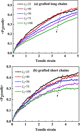
By analyzing the bond orientation behavior of each part during the uniaxial deformation, we find that the orientation degrees, both of the grafted long and short chains, decrease with the increase of Ll throughout the deformation process, as shown in Fig. 9. The curves of the matrix chains are very similar in Fig. S7 (ESI†), indicating that the increase of Ll is not conducive to the bond orientation of grafted chains. We infer that the stress differences in the five systems with different Ll are weakly affected by the bond orientation of the matrix chains, and may strongly depend on the decrease of the total non-bonded interaction energy of the system and the bond orientation of the grafted chains.
IV. Conclusions
In this study, we adopt coarse-grained molecular-dynamics simulations in order to investigate the effects of the structure and the bimodal dispersion of grafted polymer chains on the mechanical properties of the resulting PNCs. For the mechanically interlocked PNCs, we have successfully constructed an ideal mechanically interlocked structure by using two different methods, and demonstrated their remarkable mechanical reinforcement effect. One method is to change the stiffness of the matrix chains during the equilibration process. In the first equilibration step, the stiffness promotes matrix chains to thread through the grafted rings, and in the second equilibration step, their flexibility induces the locking of the resulting structure. The mechanical enhancement effect, above 200% on average, is the largest at the bending constant k = 20.0 in the first equilibration step. The second method is to change the size and the shape of the grafted rings by adjusting the equilibrium value of the corresponding bending angle θ0. For θ0 = 120° in the grafted rings and for k = 5.0 in the matrix chains, the reinforcement effect, above 700%, is the most remarkable in all the simulated systems.The mechanical properties of the composites with the bimodal polymer-grafted NPs have been analyzed. The stress–strain curves exhibit striking similarity when the fraction Cg of the grafted chains is fixed, indicating that the mechanical properties of the systems are closely related to the total number of beads of the grafted chains. Furthermore, when Cg increases with the increase of Ll, keeping the grafting density unchanged, the mechanical properties decrease monotonically. This result is attributed to the decrease of the total non-bonded interaction energy of the system in the equilibration state and to the reduced bond orientation of both the long and short grafted chains during the uniaxial deformation. In general, it is anticipated that our study could provide some guidance on tailoring the mechanical performance of grafted NP–filled polymer nanocomposites, by taking advantage of varying the structure and length of the grafted polymer chains.
Conflicts of interest
There are no conflicts to declare.Acknowledgements
We acknowledge the financial support from the Major Program (51790502) of the National Nature Science Foundation of China, the National Natural Science Foundation of China (51873006 and 21674010), the Beijing Natural Science Foundation (2182053) and the National 973 Basic Research Program of China 2015CB654700 (2015CB654704). The super-calculation center of “Tianhe number two” and the cloud calculation platform of Beijing University of Chemical Technology (BUCT) are both greatly appreciated.References
- V. M. Svetlichnyi, K. A. Romashkova, L. I. Subbotina, V. E. Yudin, E. V. Popova, I. V. Gofman, T. E. Sukhanova, E. N. Vlasova and N. V. Afanas'eva, Russ. J. Appl. Chem., 2013, 86, 415–422 CrossRef CAS.
- M. R. Bockstaller and E. L. Thomas, Phys. Rev. Lett., 2004, 93, 166106 CrossRef PubMed.
- J. Bae, E. Glogowski, S. Gupta, W. Chen, T. Emrick and T. P. Russell, Macromolecules, 2008, 41, 2722–2726 CrossRef CAS.
- C. G. Martins, N. M. Larocca, D. R. Paul and L. A. Pessan, Polymer, 2009, 50, 1743–1754 CrossRef CAS.
- S. S. Rekhviashvili, E. V. Kishtikova and B. A. Rozenberg, Russ. J. Phys. Chem. B, 2009, 3, 1008–1014 CrossRef.
- B. Natarajan, T. Neely, A. Rungta, B. C. Benicewicz and L. S. Schadler, Macromolecules, 2013, 46, 4909–4918 CrossRef CAS.
- S. Lee, B. Lee, B. J. Kim, J. Park, M. Yoo, W. K. Bae, K. Char, C. J. Hawker, J. Bang and J. Cho, J. Am. Chem. Soc., 2009, 131, 2579–2587 CrossRef CAS PubMed.
- Y. Kim, C. Lee, I. Shim, D. Wang and J. Cho, Adv. Mater., 2010, 22, 5140–5144 CrossRef CAS PubMed.
- J. Gu, Y. Yan, Y. S. Zhao and J. Yao, Adv. Mater., 2012, 24, 2249–2253 CrossRef CAS PubMed.
- M. Sureshkumar, D. Y. Siswanto and C.-K. Lee, J. Mater. Chem., 2010, 20, 6948–6955 RSC.
- V. Ganesan and A. Jayaraman, Soft Matter, 2014, 10, 13–38 RSC.
- A. Hashemi, N. Jouault, G. A. Williams, D. Zhao, K. J. Cheng, J. W. Kysar, Z. Guan and S. K. Kumart, Nano Lett., 2015, 15, 5465–5471 CrossRef CAS PubMed.
- C. Chevigny, N. Jouault, F. Dalmas, F. Boue and J. Jestin, J. Polym. Sci., Part B: Polym. Phys., 2011, 49, 781–791 CrossRef CAS.
- H. S. Wang, A. Khan, Y. Choe, J. Huh and J. Bang, Macromolecules, 2017, 50, 5025–5032 CrossRef CAS.
- J. Shen, J. Liu, Y. Gao, X. Li and L. Zhang, Soft Matter, 2014, 10, 5099–5113 RSC.
- J. Shen, J. Liu, H. Li, Y. Gao, X. Li, Y. Wu and L. Zhang, Phys. Chem. Chem. Phys., 2015, 17, 7196–7207 RSC.
- J. Liu, S. Wu, L. Zhang, W. Wang and D. Cao, Phys. Chem. Chem. Phys., 2011, 13, 518–529 RSC.
- P. Akcora, H. Liu, S. K. Kumar, J. Moll, Y. Li, B. C. Benicewicz, L. S. Schadler, D. Acehan, A. Z. Panagiotopoulos, V. Pryamitsyn, V. Ganesan, J. Ilavsky, P. Thiyagarajan, R. H. Colby and J. F. Douglas, Nat. Mater., 2009, 8, 354–359 CrossRef CAS PubMed.
- X. L. Dou, X. L. Liu, Y. Zhang, H. Feng, J. F. Chen and S. Du, Appl. Phys. Lett., 2009, 95, 306 Search PubMed.
- P. Akcora, S. K. Kumar, J. Moll, S. Lewis, L. S. Schadler, Y. Li, B. C. Benicewicz, A. Sandy, S. Narayanan, J. Illavsky, P. Thiyagarajan, R. H. Colby and J. F. Douglas, Macromolecules, 2010, 43, 1003–1010 CrossRef CAS.
- J. F. Moll, P. Akcora, A. Rungta, S. Gong, R. H. Colby, B. C. Benicewicz and S. K. Kumar, Macromolecules, 2011, 44, 7473–7477 CrossRef CAS.
- S. K. Kumar, V. Ganesan and R. A. Riggleman, J. Chem. Phys., 2017, 147, 020901 CrossRef PubMed.
- N. Molinari, A. P. Sutton and A. A. Mostofi, Phys. Chem. Chem. Phys., 2018, 20, 23085–23094 RSC.
- J. U. Kim and M. W. Matsen, Phys. Rev. Lett., 2009, 102, 078303 CrossRef PubMed.
- S. Kim, M. Yoo, N. Kang, B. Moon, B. J. Kim, S.-H. Choi, J. U. Kim and J. Bang, ACS Appl. Mater. Interfaces, 2013, 5, 5659–5666 CrossRef CAS PubMed.
- Y. Li, T. M. Krentz, L. Wang, B. C. Benicewicz and L. S. Schadler, ACS Appl. Mater. Interfaces, 2014, 6, 6005–6021 CrossRef CAS PubMed.
- D. L. Ramasamy, V. Puhakka, B. Doshi, S. Iftekhar and M. Sillanpaa, Chem. Eng. J., 2019, 365, 291–304 CrossRef CAS.
- X. D. Qian, Polym. Compos., 2018, 39, 4637–4645 CrossRef CAS.
- R. Yuan, J. Yuan, Y. P. Wu, P. F. Ju, L. Ji, H. X. Li, L. Chen, H. D. Zhou and J. M. Chen, J. Mater. Sci., 2018, 53, 11460–11472 CrossRef CAS.
- A. Alam, M. D. H. Beg, R. M. Yunus, M. Bijarimi, M. F. Mina, K. H. Maria and T. Mieno, Polym. Test., 2018, 68, 116–125 CrossRef.
- M. Kilbey, D. Street, R. Ramirez, J. Sangoro and J. Messman, Abstr. Pap. Am. Chem. Soc., 2018, 255, 2 Search PubMed.
- P. R. Ye, P. F. Cao, Q. Y. Chen and R. Advincula, Macromol. Mater. Eng., 2019, 304, 10 Search PubMed.
- A. Tibbits, K. Park, J. Streit, L. Drummy and R. Vaia, Abstr. Pap. Am. Chem. Soc., 2018, 255, 1 Search PubMed.
- X. Wang, S. Y. Jing, Y. Y. Liu, X. M. Qiu and Y. B. Tan, RSC Adv., 2017, 7, 13112–13122 RSC.
- S. K. Kumar, N. Jouault, B. Benicewicz and T. Neely, Macromolecules, 2013, 46, 3199–3214 CrossRef CAS.
- J. R. Brown, Y. Seo, T. A. Maula and L. M. Hall, J. Chem. Phys., 2016, 144, 124904 CrossRef PubMed.
- D. Maillard, S. K. Kumar, A. Rungta, B. C. Benicewicz and R. E. Prud'homme, Nano Lett., 2011, 11, 4569–4573 CrossRef CAS PubMed.
- J. Moll, S. K. Kumar, F. Snijkers, D. Vlassopoulos, A. Rungta, B. C. Benicewicz, E. Gomez, J. Ilavsky and R. H. Colby, ACS Macro Lett., 2013, 2, 1051–1055 CrossRef CAS.
- J. Shen, J. Liu, Y. Gao, D. Cao and L. Zhang, Langmuir, 2011, 27, 15213–15222 CrossRef CAS PubMed.
- D. M. Trombly and V. Ganesan, J. Chem. Phys., 2010, 133, 154904 CrossRef PubMed.
- P. F. Green, Soft Matter, 2011, 7, 7914–7926 RSC.
- S. Srivastava, P. Agarwal and L. A. Archer, Langmuir, 2012, 28, 6276–6281 CrossRef CAS PubMed.
- J. Liu, Y. Gao, D. Cao, L. Zhang and Z. Guo, Langmuir, 2011, 27, 7926–7933 CrossRef CAS PubMed.
- J. Liu, Z. Wang, Z. Zhang, J. Shen, Y. Chen, Z. Zheng, L. Zhang and A. V. Lyulin, J. Phys. Chem. B, 2017, 121, 9311–9318 CrossRef CAS PubMed.
- N. Suzuki, M. Ito and F. Yatsuyanagi, Polymer, 2005, 46, 193–201 CrossRef CAS.
- J. H. Chen, M. Z. Rong, W. H. Ruan and M. Q. Zhang, Compos. Sci. Technol., 2009, 69, 252–259 CrossRef CAS.
- M. Z. Rong, M. Q. Zhang, Y. X. Zheng, H. M. Zeng, R. Walter and K. Friedrich, Polymer, 2001, 42, 167–183 CrossRef CAS.
- S. Goyal and F. A. Escobedo, J. Chem. Phys., 2011, 135, 184902 CrossRef PubMed.
- M. Gauthier and A. Munam, Polymer, 2009, 50, 6032–6042 CrossRef CAS.
- S. K. Kumar and R. Krishnamoorti, Annu. Rev. Chem. Biomol. Eng., 2010, 1, 37–58 CrossRef CAS PubMed.
- Z. Wang, Z. Zheng, J. Liu, Y. Wu and L. Zhang, Polymers, 2016, 8, 270 CrossRef PubMed.
- V. V. Ginzburg, Macromolecules, 2013, 46, 9798–9805 CrossRef CAS.
- A. Lopez-Moreno, B. Nieto-Ortega, M. Moffa, A. de Juan, M. M. Bernal, J. P. Fernandez-Blazquez, J. J. Vilatela, D. Pisignano and E. M. Perez, ACS Nano, 2016, 10, 8012–8018 CrossRef CAS PubMed.
- E. M. Perez, Chem. – Eur. J., 2017, 23, 12681–12689 CrossRef CAS PubMed.
- Y. Li, P. Tao, A. Viswanath, B. C. Benicewicz and L. S. Schadler, Langmuir, 2013, 29, 1211–1220 CrossRef CAS PubMed.
- A. Rungta, B. Natarajan, T. Neely, D. Dukes, L. S. Schadler and B. C. Benicewicz, Macromolecules, 2012, 45, 9303–9311 CrossRef CAS.
- R. Shi, H.-J. Qian and Z.-Y. Lu, Phys. Chem. Chem. Phys., 2017, 19, 16524–16532 RSC.
- Z. Shen, L. Zhang, J. Cao, J. Tian, L. Liu, G. Wang, Z. Zhao, X. Wang, R. Zhang and S. Liu, J. Environ. Monit., 2012, 14, 3000–3008 RSC.
- K. Kremer and G. S. Grest, J. Chem. Phys., 1991, 94, 4103 CrossRef CAS.
- N. Goga, M. N. Melo, A. J. Rzepiela, A. H. de Vries, A. Hadar, S. J. Marrink and H. J. C. Berendsen, J. Chem. Theory Comput., 2015, 11, 1389–1398 CrossRef CAS PubMed.
- M. K. Crawford, R. J. Smalley, G. Cohen, B. Hogan, B. Wood, S. K. Kumar, Y. B. Melnichenko, L. He, W. Guise and B. Hammouda, Phys. Rev. Lett., 2013, 110, 196001 CrossRef CAS PubMed.
- S. N. Mohammad, Nanotechnology, 2012, 23, 285707 CrossRef PubMed.
- M. Kroger and S. Hess, Phys. Rev. Lett., 2000, 85, 1128–1131 CrossRef CAS PubMed.
- G. N. Toepperwein, N. C. Karayiannis, R. A. Riggleman, M. Kroeger and J. J. de Pablo, Macromolecules, 2011, 44, 1034–1045 CrossRef CAS.
- G. Srinivas, D. E. Discher and M. L. Klein, Nat. Mater., 2004, 3, 638–644 CrossRef CAS PubMed.
- G. Raos, M. Moreno and S. Elli, Macromolecules, 2006, 39, 6744–6751 CrossRef CAS.
- B. Ensing, S. O. Nielsen, P. B. Moore, M. L. Klein and M. Parrinello, J. Chem. Theory Comput., 2007, 3, 1100–1105 CrossRef CAS PubMed.
- Y. Zhang, P. Tiwary, J. S. Parent, M. Kontopoulou and C. B. Park, Polymer, 2013, 54, 4814–4819 CrossRef CAS.
- G. Hou, X. Xia, J. Liu, W. Wang, M. Dong and L. Zhang, J. Phys. Chem. B, 2019, 123, 2157–2168 CrossRef CAS PubMed.
- G. Buck and E. J. Rawdon, Phys. Rev. E: Stat., Nonlinear, Soft Matter Phys., 2004, 70, 011803 CrossRef PubMed.
- R. Everaers, S. K. Sukumaran, G. S. Grest, C. Svaneborg, A. Sivasubramanian and K. Kremer, Science, 2004, 303, 823–826 CrossRef CAS PubMed.
- S. K. Sukumaran, G. S. Grest, K. Kremer and R. Everaers, J. Polym. Sci., Part B: Polym. Phys., 2005, 43, 917–933 CrossRef CAS.
- J. Liu, Z. Zheng, F. Li, W. Lei, Y. Gao, Y. Wu, L. Zhang and Z. L. Wang, Nano Energy, 2016, 28, 87–96 CrossRef CAS.
- W. Wang, G. Hou, Z. Zheng, L. Wang, J. Liu, Y. Wu, L. Zhang and A. V. Lyulin, Phys. Chem. Chem. Phys., 2017, 19, 15808–15820 RSC.
- P. Norouzzadeh, A. Nozariasbmarz, J. S. Krasinski and D. Vashaee, J. Appl. Phys., 2015, 117, 214303 CrossRef.
- J. Liu, J. X. Shen, D. P. Cao and L. Q. Zhang, Acta Polym. Sin., 2016, 8, 1048–1061 Search PubMed.
Footnote |
| † Electronic supplementary information (ESI) available. See DOI: 10.1039/c9cp02948f |
| This journal is © the Owner Societies 2019 |

