 Open Access Article
The effect of the magnitude and direction of the dipoles of organic cations on the electronic structure of hybrid halide perovskites†
Sudeep
Maheshwari
a,
Sameer
Patwardhan
b,
George C.
Schatz
 b,
Nicolas
Renaud
c and
Ferdinand C.
Grozema
 *a
*a
aDepartment of Chemical Engineering, Delft University of Technology, P.O. Box 5045, 2629 HZ Delft, The Netherlands. E-mail: f.c.grozema@tudelft.nl; Fax: +31(0)15 2783914; Tel: +31(0)15 2783914
bArgonne-Northwestern Solar Energy Research (ANSER) Center and Department of Chemistry, Northwestern University, Evanston, Illinois 60208-3113, USA
cNetherlands eScience Center, Science Park 140, 1098 XG Amsterdam, The Netherlands
First published on 5th July 2019
Abstract
We present ab initio calculations (DFT and SOC-G0W0) of the optoelectronic properties of different hybrid-halide perovskites, namely X–PbI3 (X = methylamonimum, formamidinium, guanidinium, hydrazinium, and hydroxylammonium). These calculations shed new light on how the substitution of different organic cations in the material influences its optoelectronic properties. Our simulations show a significant modification of the lattice parameter and band gap of the material upon cation substitution. These modifications are not only due to steric effects but also due to electrostatic interactions between the organic and inorganic parts of the material. In addition to this, we demonstrate how the relative orientations of neighboring cations in the material modify the local electrostatic potential of the system and its fundamental band gap. This change in the band gap is accompanied by the formation of localized and spatially separated electronic states. These localized states modify the carrier mobility in the materials and can be a reason for the formation and recombination of the charge carriers in these very promising materials.
1 Introduction
Hybrid halide perovskites are currently among the most studied new materials for application in photovoltaic cells. The main reason for this is the rapid increase in the device efficiency over the last few decades, reaching values over 23%.1–3 The high efficiencies that have been obtained can be traced back to some of the basic properties of hybrid perovskite materials, i.e. a high absorption coefficient, long carrier lifetimes and diffusion lengths, a relatively high charge carrier mobility, and the possibility to tune the properties by modification of the composition of the materials.4–10 An additional advantage of hybrid perovskites is that they potentially have a very low production cost.11The general ABX3 structure of hybrid halide perovskite (HHP) materials allows for substitution of the organic cation (A), inorganic cation (B) and halide anions (X). Hence a large number of structural variations have been reported, each leading to different optoelectronic properties of the materials. Among all the structures, methylammonium lead iodide (CH3NH3PbI3) perovskites have been studied the most as they were the first to be used as light absorbers in mesoscopic solar cells.12 Several theoretical studies have shown that the valence band of this material is mainly composed of p-orbitals of iodides whereas the conduction band consists primarily of s-orbitals of lead.13
Recently the static and dynamic effects related to the organic cation have emerged as a new avenue to understand and control the properties of HHPs. It has been shown for example that if the methylammonium cation is replaced by a slightly larger formamidinium cation the band gap is reduced by 0.05 eV, whereas when replaced by a smaller cesium ion, it increases by 0.16 eV.14–16 It has also been shown that a mixed cation material, containing formamidinium and cesium, exhibits reduced electron hole recombination through lattice contraction and tilting of the lead iodide octahedra.17 Such modifications of the electronic structure originate from two main effects: steric hindrance for large organic cations that deforms the lead-iodide lattice18 and electrostatic effects for cations resulting in a significant dipole moment. In addition, NMR and neutron diffraction studies have shown that these cations are to some extent free to rotate in the lead-iodide cage.19 This dynamic behavior can also lead to significant modifications of the dielectric constant, the rate of charge recombination and exciton binding energy of the material.20
We have demonstrated the role of the methylammonium cation dynamics in determining the mobility and lifetime of charge carriers.21 Based on the pulse-radiolysis microwave conductivity measurement we have shown that the mobility and lifetime of charge carriers are significantly affected by the dynamic disorder in the CH3NH3PbI3 perovskite. The transition to the orthorhombic phase leads to an increase in the mobility and half-lifetime of the charge carriers. This is attributed to the fact that in the orthorhombic phase, the motion of the MA cation ceases thus expelling the dynamic disorder from the system. The free rotation of the cations also leads to a pronounced ferroelectric response of the material to an external field.22,23 This ferroelectric effect leads to the polarization of the whole lattice and promotes charge separation.24 A similar orientation of the dipoles in these domains leads to local variations in the band gap.24 Theoretical calculations have also shown that a random orientation of the dipoles can significantly localize the valence and conduction bands of the material.25
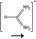
In this paper we investigate the structure–property relationship of hybrid halide perovskites with a special emphasis on the role played by the dipole moment of organic cations. To understand the steric and electrostatic impact of the cations on the electronic properties of the material, we have chosen five organic cations with different sizes and dipole moments as shown in Table 1. We show that depending on the mutual orientation of the dipolar organic cations, localized states can be formed where electrons and holes are located in different parts of the material. This is expected to result in long carrier lifetimes, particularly at low temperatures where the organic cations are frozen in a fixed orientation.
2 Methods
For the calculation of the dipole moment, an augmented correlation consistent polarized valence (aug-cc-pVTZ) basis set was chosen along with BLYP functional combining the Becke exchange functional and LYP correlational functional in Gaussian 09.26 Optimization of the different X–PbI3 structures (where X = methylamonimum, formamidinium, guanidinium, hydrazinium, and hydroxylammonium) was performed using projector augmented wave (PAW) pseudopotentials with the van der Waals corrected PBE exchange–correlation functional as implemented in VASP 5.4.1. and identified as DFT-D3.27–31 An energy cut off of 500 eV and a gamma-centered Brillouin zone sampling grid of 8 × 8 × 8 were chosen for these calculations. The ionic positions were relaxed while conserving the lattice shape for continuous values of the lattice parameter. Band structures of the different X–PbI3 materials were then computed at the DFT level of theory at a denser mesh containing 600 k-points. The band gap was again computed at the SOC-G0W0 level of theory including local field effects.27,28,30,31 The electrostatic potential of the system was obtained using VASP with ionic and Hartree potential. Atomic charges on the atoms were obtained by Bader's population analysis after DFT calculations.32 The total energy of the point charge system was computed with GULP, using Ewald summation to account for periodic boundary conditions.333 Results and discussion
3.1 The effect of cation substitution on the lattice size and the band gap
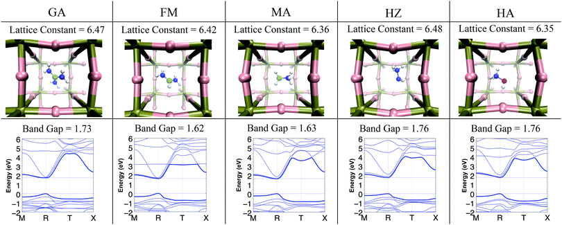
The substitution of the organic cation X in X–PbI3 and the development of mixed organic cation XnY1−n–PbI3 hybrid perovskites with multiple combinations of organic cations have been performed. It is generally believed that smaller organic cations contract the lattice and increase the bandgap whereas larger cations expand the lattice and decrease the bandgap.35 With this assumption, the organic cation interaction because of its dipole moment with the lead and iodide atoms is generally overlooked. This interaction has the possibility to modify the charge density distribution of the lead and iodide atoms and thus modify the electronic properties. The geometry of the different X–PbI3 (where X = GA, FM, MA, HZ, and HA) structures was optimized to gain insight into the effect of cation substitution on the size of the unit-cell.The optimized value of the lattice constant and the corresponding optimized geometry are reported in Fig. 1. The structural parameters of the optimized geometry and the electronic band gap are reported in Table 2. As seen in this table, the lattice constants computed at the DFT-D3 level of theory for MA and FM are in good agreement with the experimental data. It is also seen that the lattice constant varies non-linearly with the size of the cation suggesting that there are more interactions that play a role than just the steric repulsion between the cation and lead-iodide frameworks. For example, despite being the smallest cation, HZ has a larger lattice constant than other cations. However as seen in Table 1, HZ has a large dipole moment. GA being the biggest in size among the five cations assumes a unit-cell that is slightly smaller than that of HZ. This illustrates how both electrostatic effects and specific interactions, together with steric effects, significantly influence the atomistic structure of these materials. Apart from affecting the size of the unit cell, these interactions also have a significant impact on the Pb–I–Pb angles as seen in Table 2. The stronger the steric and electrostatic interactions between the organic cation and the Pb–I lattice, the larger the change in the Pb–I–Pb angles from 180°. As seen in Table 2 the average of the Pb–I–Pb angles deviates from the ideal 180° angle in the order FM < MA < GA < HZ < HA.
| In X–PbI3, X = | GA | FM | MA | HZ | HA |
|---|---|---|---|---|---|
| Lattice constant | 6.47 | 6.42 [6.36*] | 6.36 [6.33*] | 6.48 | 6.35 |
| Bond angles ∠Pb–I–Pb | 169 | 168 | 172 | 172 | 166 |
| 169 | 174 | 169 | 167 | 168 | |
| 169 | 175 | 169 | 166 | 167 | |
| Average angle ∠Pb–I–Pb | 169 | 173 | 170 | 168 | 167 |
| Band gap (DFT) | 1.73 | 1.62 | 1.63 | 1.76 | 1.76 |
| Band gap (SOC-G0W0) | 1.68 | 1.50 [1.47*] | 1.55 [1.53*] | 1.84 | 1.79 |
The optimized geometries obtained at the DFT-D3 level of theory were used to compute the band structure of the materials. The resulting band structure and band gap are shown in Fig. 1 and Table 2. As seen in this figure, the values of the band gap obtained at the SOC G0W0 level of theory are in good agreement with the available experimental data. The values of the band gap show an increase in the order FM < MA < GA < HA ≈ HZ. The trend of increasing band gaps coincides with the trend in the deviation of the Pb–I–Pb angles from the ideal 180° angle. Here the HZ cation shows an abnormally high band gap at the G0W0 level of theory, which is a result of the larger lattice constant for the cation. These calculations show that the Pb–I–Pb angles and the lattice constants of the system have a direct impact on the fundamental band gap of the material and are in contrast with the observed pattern of the ionic radii of the organic cation affecting the bandgap of the material. The Pb–I–Pb angles are determined by the steric and electrostatic interactions in the system, and therefore indirectly affect the band gap of the system. This finding is consistent with the earlier reports of Filip et al.36
3.2 The effect of dipole orientations
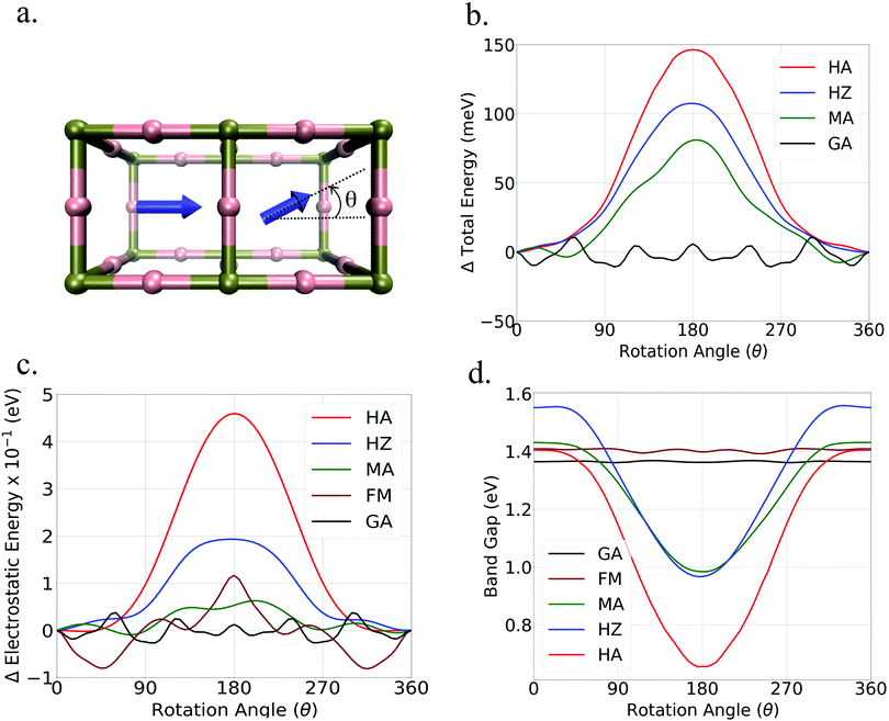
To understand how disorder in the orientation of the dipolar organic cations affects the electronic properties of the perovskites we have studied variations in the electronic structure induced by the rotation of a dipole in extended systems. To achieve this, we have considered two neighboring unit cells as shown in Fig. 2. As seen in this figure, the orientation of one cation was kept fixed while continuously rotating the cation located in the neighboring unit cell. Throughout the calculations, the lead-iodide framework was kept fixed in a perfectly cubic arrangement to address only the effect of dipole rotation without any influence of lattice deformation. The values of the total energy obtained for the different cation arrangements are reported in Fig. 2b. As seen in this figure, a considerable variation in the total energy of the system was observed upon rotation of the cations with high dipole moment, i.e. MA, HZ, and HA. For these cations a maximum energy ranging from 80 meV to 150 meV was obtained for anti-parallel orientations of the neighboring dipoles. These values are in good agreement with the ones reported by Quarti et al.37 It is also observed that the variation of the total energy for low dipole moment cations was much smaller, as expected.To clarify whether repulsive dipole–dipole interactions are responsible for the trend in the total energy obtained from the DFT calculation we have separately calculated the electrostatic interactions in the systems using a point charge model. The variation of electrostatic energy per unit cell with the rotation of dipoles is shown in Fig. 2c. As seen in this figure, these variations follow the same trend as observed from the DFT calculations, with a maxima in the anti-parallel configuration. This confirms the crucial role of electrostatic interaction in determining the cation arrangement in HHP materials. The relatively low energy barriers for dipole rotation suggest that anti-parallel configurations of dipoles may exist even at room temperature, albeit in small concentrations.
Fig. 2d shows the variations in the band gap upon rotation of the cations. As seen in this figure, a considerable reduction of the band gap was obtained for anti-parallel configurations of high dipole moment cations. The relative change in the band gap from a parallel to an anti-parallel configuration is 31% for MA, 38% for HZ and 53% for HA. In contrast, the low dipole moment cations show a minimal variation in the band gap with a change in the mutual orientation of the cations.
These calculations clearly show that even though organic cations do not participate directly in the valence and conduction band energy states, their orientations can significantly affect the energy level of these bands via electrostatic interactions. The effect of the mutual orientation of the dipoles on the electronic structure will also strongly depend on rotational dynamics. Hence rotational dynamics will significantly affect the eventual effect of the dipolar cations on the experimentally observed band gap.
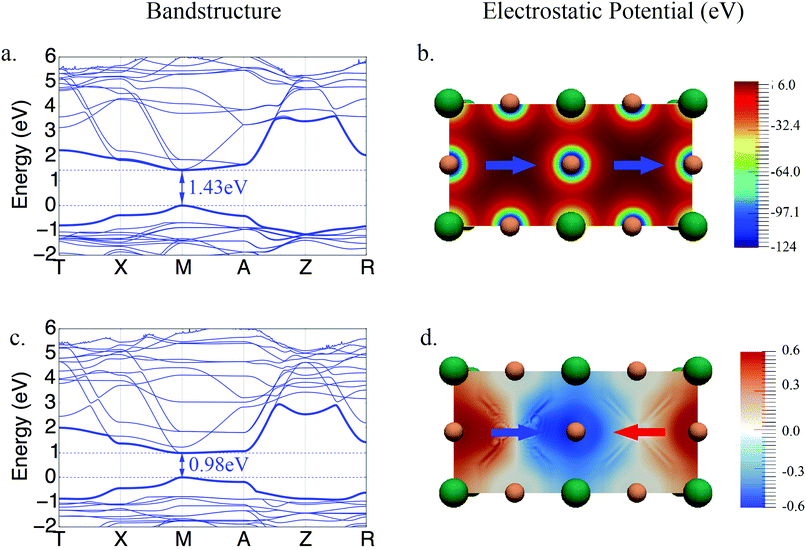
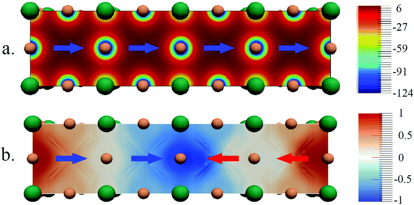
The band structures for the parallel and anti-parallel orientations of MAPbI3 in Fig. 3a and c clearly show a dependence on the orientation of the MA cation. An anti-parallel orientation of cations decreases the distance between the valence and conduction bands and is accompanied by a change in the curvature of the bands. These changes in the electronic structure can be related to the changes in the electrostatic potential due to the organic cations upon rotation. The electrostatic potential is uniformly distributed across the system consisting of two unit cells when both dipoles have the same direction, as shown in Fig. 3b.
However, when the dipoles are anti-parallel, the electrostatic potential distribution becomes non uniform between the adjoining unit cells. It should be noted that the variation in the magnitude of the potential is rather small since the electrostatic potential is dominated by the full positive charge on the organic cation. To illustrate the small but significant variation of the electrostatic potential we have calculated the difference between the electrostatic potential of systems with anti-parallel and parallel orientations of cations, Vnet = Vanti-parallel − Vparallel, shown in Fig. 3d. It can be seen here that the potential is lower at the interface between the unit cells, where the positive end dipoles point towards each other, and is higher at the interface where the tails of the dipoles are closer. The difference between the total electrostatic potentials in the two spatial locations is 1.2 eV.
3.3 Localization effects due to dipole orientations
To understand the impact of the relative orientation of organic cations on the electronic states in disordered perovskites, we have considered a super-cell composed of four individual unit cells. A schematic of this can be seen in Fig. 4 and 6. As seen in these figures, two different configurations of the organic cations are considered, (i) the four cations aligned in the same direction i.e. in parallel and (ii) the two cations aligned anti-parallel to the other two thus creating an anti-parallel dipole domain. The electronic structure of these systems was then studied for MA (Fig. 4) and FM (Fig. 6). In each case, the band-decomposed charge density was extracted to visualize the electronic states corresponding to the valence band maximum and the conduction band minimum. | ||
| Fig. 4 Band gap and distribution of electronic states of MAPbI3 in the case of (a) parallel orientation of dipoles and (b) anti-parallel orientation of dipoles. | ||
As seen in Fig. 4, the electronic states of the valence band maximum and the conduction band minimum for MAPbI3 are completely delocalized over whole super-cell when dipoles are in a parallel configuration. The band gap of the system in this case is 1.43 eV. When the system with an anti-parallel configuration of dipoles is considered, the electronic states of the valence and conduction bands become localized at the interfaces between the newly created domain. The band gap for this configuration decreases to 0.41 eV, which is even lower than that for the anti-parallel configuration of the two unit cells as seen in Fig. 3. To understand the reason for this localization of states and lowering of the band gap, the electrostatic potential was plotted again for the parallel and anti-parallel orientations of dipoles. As seen in Fig. 5 the electrostatic potential remains uniformly distributed when all dipoles are in the parallel orientation, but becomes non-uniform for the anti-parallel orientation. It is important to note that the electrostatic potential shown in Fig. 3 and 4 is a combined effect of the DFT electron density of the organic cations and inorganic lead-iodide atoms and not just the dipolar cations. The anti-parallel orientation of the MA dipoles polarize the electron distribution of the Pb–I framework, leading to an overall increase in the electron density between the heads or the δ-positive end of anti-parallel dipoles. The difference in the potential between the high and low relative potential increases from 1.2 eV to 2 eV when moving from a system of two anti-parallel cations in a double unit cell to four anti-parallel cations in a quadruple unit cell. This shows that increasing the size of the organized domains leads to more pronounced electrostatic potentials at the interfaces between the domains. From the localization of the conduction band in the region where the MA dipoles point towards each other, it becomes clear that this is where an excess amount of electrons will be localized, while an excess amount of positive charges will become localized at the negative end of the dipoles, as evidenced by the density for the valence band maximum; see Fig. 4a. Thus we can conclude that the local electrostatic environment has a pronounced influence on the localization of the electronic bands in these materials, which results in a variation in the band gap. Note that the band gaps in the parallel orientation shown in Fig. 4 and 6 deviate from those listed in Table 2. This is because the structures used in these figures are not relaxed, the dipole moments have been fixed to reach the desired alignment and the structure of the Pb–I lattice has not been relaxed. As is shown in the ESI,† this relaxation only slightly affects the structure and band gap. It should be noted that the number of unit cells at the interface between different aligned domains will be very small compared to those inside the larger domains. This means that in the experiments the band gap will be dominated by the states inside the domains that are characterized by a larger band gap.
To confirm the role played by electrostatic interactions in the localization of the electronic states we have performed similar calculations with low dipole moment FM. The results presented in Fig. 6 show that the delocalization of the electronic state here is not affected by the rearrangement of the cations in this case. Furthermore, the band gap of the system is almost independent of the orientation of the cation. This clearly demonstrates that the rotation of cations with low dipole moment do not have a significant effect on the electronic structure of the material. Thus, only cations with significantly high dipole moment can alter the local electrostatic potential in the system and can significantly influence the electronic properties.
 | ||
| Fig. 6 Band gap and distribution of electronic states of FMPbI3 in the case of (a) parallel orientation of dipoles, (b) anti-parallel orientation of dipoles. | ||
To gain insight into the effect of formation of localized electronic states on the effective mass of the charge carriers, we have calculated the effective mass in systems with uniform dipole directions and for the anti-parallel domains as reported in Table 3. For a uniform direction of dipoles the effective mass is the same in all directions and values of 0.1 m0 and 0.58 m0 are found for the hole and the electron, respectively. The effective masses for the system of four unit cells with anti-parallel dipoles were estimated by the band fitting method in the three orthogonal directions for the localized states, in which X corresponds to the direction of dipoles, and Y and Z are two orthogonal directions. For the direction perpendicular to the orientation of the dipoles, effective mass values that are similar to those for the system without anti-parallel dipoles are obtained. This shows that similar charge mobilities can be expected in these directions. In the X-direction, corresponding to the direction of the dipoles, the effective masses are considerably larger. This shows that transport from one localized domain to the other is relatively inefficient and hence the charges will remain separated in their respective domains. This may result in a slower recombination of electrons and holes in this material if the dipole orientations are static.
| Parallel dipoles | Anti-parallel dipoles | |||
|---|---|---|---|---|
| X, Y and Z | X | Y | Z | |
| m h* | 0.15 | 0.36 | 0.15 | 0.15 |
| m e* | 0.58 | 13.04 | 0.91 | 0.75 |
Berdiyorov et al. have shown by electron localization calculation that the transport in the direction lateral to the dipolar axis increases because of the variation of electrostatic potential which directly supports our claim.38 This was also observed in our previous experimental work in which an increased mobility was observed at lower temperatures as the dipoles were immobilized.21
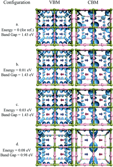
Different arrangements of cations of MAPbI3 were considered to understand the conditions required for the formation of such localized states. A few of these conformations are shown in Fig. 7. Configuration a, where all the dipoles have the same orientation, is the most energetically favorable conformation. The introduction of disorder in the cation orientation without the creation of clear domains, such as in conformations b and c, does not significantly change the band gap, nor does it lead to the formation of localized states. Only the creation of well-defined boundaries between domains, as in conformation d, induce the formation of localized states at the domain walls. Note that the formation energy of such a conformation is only 80 meV above the energy of conformation a. This energy difference suggests that the formation of such local domains can take place at room temperature.
4 Conclusions
The calculations presented in this work show that the substitution of cations with varying sizes and dipole moments in the lead iodide framework has a pronounced effect on the electronic structure of the material by modulating the bond angles Pb–I–Pb. The relative orientation of dipoles also significantly affects the electronic structure and band gap of the hybrid halide perovskites. The larger the dipole moment of the organic cation, the larger its effect on the electronic structure. A larger dipole moment also leads to a larger energy barrier for the rotation of the dipoles. In the case of MA, the barrier is 80 meV, indicating that at room temperature the anti-parallel configuration of dipoles can be accessed in small concentrations. Despite small concentrations of this configuration, significant effects on the local electrostatic environment and the local electronic properties can be observed. The band gap of the system decreases upon rotation of the high dipole moment cations in the anti-parallel orientation. This decrease is attributed to the change in the local electrostatic environment of the system. The anti-parallel orientation of dipoles results in the formation of localized electronic states of valence and conduction bands. The valence band becomes localized in the region of higher electrostatic potential whereas the conduction band becomes localized in the region of low electrostatic potential. This localization leads to a decrease in the band gap of the system. The creation of these local domains also influences the effective masses of charge carriers as electrons and holes become heavier in the direction of the dipolar axis.Conflicts of interest
There are no conflicts to declare.Acknowledgements
This work is part of an Industrial Partnership Programme of the Foundation for Fundamental Research on Matter (FOM), which is part of the Netherlands Organisation for Scientific Research (NWO). The research leading to these results in the Delft University of Technology has received funding from the European Research Council Horizon 2020 ERC Grant Agreement no. 648433.Notes and references
- J. C. Brauer, Y. H. Lee, M. K. Nazeeruddin and N. Banerji, J. Phys. Chem. Lett., 2015, 6, 3675–3681 CrossRef CAS
.
- NREL Best Research Cell Efficiency, howpublished = https://www.nrel.gov/pv/assets/images/efficiency-chart.png, note = accessed: 2018-05-14.
- S. S. Shin, E. J. Yeom, W. S. Yang, S. Hur, M. G. Kim, J. Im, J. Seo, J. H. Noh and S. I. Seok, Science, 2017, 356, 167–171 CrossRef CAS
.
- J. H. Noh, S. H. Im, J. H. Heo, T. N. Mandal and S. I. Seok, Nano Lett., 2013, 13, 1764–1769 CrossRef CAS
.
- S. Sun, T. Salim, N. Mathews, M. Duchamp, C. Boothroyd, G. Xing, T. C. Sum and Y. M. Lam, Energy Environ. Sci., 2014, 7, 399 RSC
.
- G. Xing, N. Mathews, S. Sun, S. S. Lim, Y. M. Lam, M. Grätzel, S. Mhaisalkar and T. C. Sum, Science, 2013, 342, 344–347 CrossRef CAS
.
- S. D. Stranks, G. E. Eperon, G. Grancini, C. Menelaou, M. J. P. Alcocer, T. Leijtens, L. M. Herz, A. Petrozza and H. J. Snaith, Science, 2013, 342, 341–344 CrossRef CAS
.
- C. Quarti, E. Mosconi, J. M. Ball, V. D'Innocenzo, C. Tao, S. Pathak, H. J. Snaith, A. Petrozza and F. De Angelis, Energy Environ. Sci., 2016, 9, 155–163 RSC
.
- G. E. Eperon, S. D. Stranks, C. Menelaou, M. B. Johnston, L. M. Herz and H. J. Snaith, Energy Environ. Sci., 2014, 7, 982–988 RSC
.
- G. E. Eperon, T. Leijtens, K. A. Bush, R. Prasanna, T. Green, J. T.-W. Wang, D. P. McMeekin, G. Volonakis, R. L. Milot, R. May, A. Palmstrom, D. J. Slotcavage, R. A. Belisle, J. B. Patel, E. S. Parrott, R. J. Sutton, W. Ma, F. Moghadam, B. Conings, A. Babayigit, H.-G. Boyen, S. Bent, F. Giustino, L. M. Herz, M. B. Johnston, M. D. McGehee and H. J. Snaith, Science, 2016, 354, 861–865 CrossRef CAS
.
- H. J. Snaith, J. Phys. Chem. Lett., 2013, 4, 3623–3630 CrossRef CAS
.
- A. Kojima, K. Teshima, Y. Shirai and T. Miyasaka, J. Am. Chem. Soc., 2009, 131, 6050–6051 CrossRef CAS
.
- G. Giorgi, J.-I. Fujisawa, H. Segawa and K. Yamashita, J. Phys. Chem. Lett., 2013, 4, 4213–4216 CrossRef CAS
.
- T. Koh, K. Fu, Y. Fang, S. Chen, T. Sum, N. Mathews, S. Mhaisalkar, P. Boix and T. Baikie, J. Phys. Chem. C, 2014, 118, 16458–16462 CrossRef CAS
.
- A. Walsh, J. Phys. Chem. C, 2015, 119, 5755–5760 CrossRef CAS PubMed
.
- G. E. Eperon, G. M. Paternò, R. J. Sutton, A. Zampetti, A. A. Haghighirad, F. Cacialli and H. J. Snaith, J. Mater. Chem. A, 2015, 3, 19688–19695 RSC
.
- L. Qiao, X. Sun and R. Long, J. Phys. Chem. Lett., 2019, 10, 672–678 CrossRef
.
- C. Motta, F. El-Mellouhi, S. Kais, N. Tabet, F. Alharbi and S. Sanvito, Nat. Commun., 2015, 6, 7026 CrossRef CAS
.
- M. T. Weller, O. J. Weber, J. M. Frost and A. Walsh, J. Phys. Chem. Lett., 2015, 6, 3209–3212 CrossRef CAS
.
- T. Chen, B. J. Foley, B. Ipek, M. Tyagi, J. R. D. Copley, C. M. Brown, J. J. Choi and S.-H. Lee, Phys. Chem. Chem. Phys., 2015, 17, 31278–31286 RSC
.
- M. C. Gélvez-Rueda, D. H. Cao, S. Patwardhan, N. Renaud, C. C. Stoumpos, G. C. Schatz, J. T. Hupp, O. K. Farha, T. J. Savenije, M. G. Kanatzidis and F. C. Grozema, J. Phys. Chem. C, 2016, 120, 16577–16585 CrossRef
.
- C. C. Stoumpos, C. D. Malliakas and M. G. Kanatzidis, Inorg. Chem., 2013, 52, 9019–9038 CrossRef CAS
.
- Y. Kutes, L. Ye, Y. Zhou, S. Pang, B. D. Huey and N. P. Padture, J. Phys. Chem. Lett., 2014, 5, 3335–3339 CrossRef CAS
.
- A. M. A. Leguy, J. M. Frost, A. P. McMahon, V. G. Sakai, W. Kochelmann, C. Law, X. Li, F. Foglia, A. Walsh, B. C. O'Regan, J. Nelson, J. T. Cabral and P. R. F. Barnes, Nat. Commun., 2015, 6, 7124 CrossRef
.
- J. Ma and L. Wang, Nano Lett., 2015, 15, 248–253 CrossRef CAS
.
-
M. J. Frisch, G. W. Trucks, H. B. Schlegel, G. E. Scuseria, M. A. Robb, J. R. Cheeseman, G. Scalmani, V. Barone, B. Mennucci, G. A. Petersson, H. Nakatsuji, M. Caricato, X. Li, H. P. Hratchian, A. F. Izmaylov, J. Bloino, G. Zheng, J. L. Sonnenberg, M. Hada, M. Ehara, K. Toyota, R. Fukuda, J. Hasegawa, M. Ishida, T. Nakajima, Y. Honda, O. Kitao, H. Nakai, T. Vreven, J. A. Montgomery, Jr., J. E. Peralta, F. Ogliaro, M. Bearpark, J. J. Heyd, E. Brothers, K. N. Kudin, V. N. Staroverov, R. Kobayashi, J. Normand, K. Raghavachari, A. Rendell, J. C. Burant, S. S. Iyengar, J. Tomasi, M. Cossi, N. Rega, J. M. Millam, M. Klene, J. E. Knox, J. B. Cross, V. Bakken, C. Adamo, J. Jaramillo, R. Gomperts, R. E. Stratmann, O. Yazyev, A. J. Austin, R. Cammi, C. Pomelli, J. W. Ochterski, R. L. Martin, K. Morokuma, V. G. Zakrzewski, G. A. Voth, P. Salvador, J. J. Dannenberg, S. Dapprich, A. D. Daniels, Ã. Farkas, J. B. Foresman, J. V. Ortiz, J. Cioslowski and D. J. Fox, Gaussian09 Revision E.01, Gaussian Inc., Wallingford CT, 2009 Search PubMed
.
- P. E. Blöchl, Phys. Rev. B: Condens. Matter Mater. Phys., 1994, 50, 17953–17979 CrossRef
.
- G. Kresse and D. Joubert, Phys. Rev. B: Condens. Matter Mater. Phys., 1999, 59, 1758–1775 CrossRef CAS
.
- S. Grimme, J. Antony, S. Ehrlich and H. Krieg, J. Chem. Phys., 2010, 132, 154104 CrossRef
.
- J. P. Perdew, K. Burke and M. Ernzerhof, Phys. Rev. Lett., 1997, 78, 1396 CrossRef CAS
.
- J. P. Perdew, K. Burke and M. Ernzerhof, Phys. Rev. Lett., 1996, 77, 3865–3868 CrossRef CAS
.
- M. Yu and D. Trinkle, J. Chem. Phys., 2011, 134, 064111 CrossRef
.
- J. D. Gale, J. Chem. Soc., Faraday Trans., 1997, 93, 629–637 RSC
.
- W.-J. Yin, J.-H. Yang, J. Kang, Y. Yan and S.-H. Wei, J. Mater. Chem. A, 2015, 3, 8926–8942 RSC
.
- A. K. Jena, A. Kulkarni and T. Miyasaka, Chem. Rev., 2019, 119, 3036–3103 CrossRef CAS
.
- M. R. Filip, G. E. Eperon, H. J. Snaith and F. Giustino, Nat. Commun., 2014, 5, 5757 CrossRef CAS
.
- C. Quarti, E. Mosconi and F. De Angelis, Chem. Mater., 2014, 26, 6557–6569 CrossRef CAS
.
- G. R. Berdiyorov, F. El-Mellouhi, M. E. Madjet, F. H. Alharbi and S. N. Rashkeev, Appl. Phys. Lett., 2016, 108, 053901 CrossRef
.
Footnote |
| † Electronic supplementary information (ESI) available. See DOI: 10.1039/c9cp02866h |
| This journal is © the Owner Societies 2019 |


