Thermodynamics and reaction mechanism of urea decomposition†
Received
18th March 2019
, Accepted 5th July 2019
First published on 8th July 2019
Abstract
The selective catalytic reduction technique for automotive applications depends on ammonia production from a urea–water solution via thermolysis and hydrolysis. In this process, undesired liquid and solid by-products are formed in the exhaust pipe. The formation and decomposition of these by-products have been studied by thermogravimetric analysis and differential scanning calorimetry. A new reaction scheme is proposed that emphasizes the role of thermodynamic equilibrium of the reactants in liquid and solid phases. Thermodynamic data for triuret have been refined. The observed phenomenon of liquefaction and re-solidification of biuret in the temperature range of 193–230 °C is explained by formation of a eutectic mixture with urea.
1 Introduction
Air pollution by nitrogen oxides from Diesel engines is a major problem concerning the environment and society. Therefore, governments follow the need to regulate emissions by law (e.g., 715/2007/EG, “Euro 5 and Euro 6”).1 The favored method to reduce nitrogen oxides is selective catalytic reduction (SCR) using ammonia as a reducing agent. Due to security issues, passenger cars cannot be equipped with an ammonia tank. Consequently, ammonia is provided in the form of a urea–water solution, which decomposes through thermolysis and hydrolysis when dispersively dosed into the hot exhaust pipe. During the desired decomposition of urea at temperatures above 130 °C, undesired intermediates and by-products in liquid and solid form are produced and stick to the wall of the exhaust pipe due to the inevitable spray–wall interaction.2–4 These condensed deposits in the exhaust pipe bear the risk of increased pressure drop and insufficient conversion to ammonia. Thus, there is a need to understand the decomposition kinetics of urea and its by-products, which has been extensively studied by many authors.5–11 Common experimental methods include Thermogravimetric Analysis (TG), Differential Scanning Calorimetry (DSC), High Performance Liquid Chromatography (HPLC) and Fourier transform-infrared (FT-IR) spectroscopy.
A first detailed description of urea decomposition behavior was proposed by Schaber et al.8 based on TG, HPLC, FT-IR and ammonium ISE (ion-selective electrode) measurements. Concluding from experimental results and literature data, 23 possible reactions including urea and its by-products biuret, cyanuric acid, ammelide, ammeline and melamine are presented. Further, cyanate and cyanurate salts and cyanamide are proposed as possible intermediates of high temperature urea decomposition. Triuret production and decomposition are not accounted for in this study. The authors classify urea decomposition into four temperature regions. The first temperature regime from room temperature to 190 °C comprises urea melting and vaporization starting from 133 °C. With increasing temperature, urea decomposes to ammonia and isocyanic acid, the latter leading to biuret, cyanuric acid and ammelide formation. The second temperature region of 190–250 °C is dedicated to biuret decomposition accompanied by several side reactions forming cyanuric acid and ammelide. At 225 °C, the melt is observed to be converted into a sticky, solid matrix, which is assumed to originate from ionic formations of different by-products without evidence. Besides small amounts of ammelide, ammeline and melamine, cyanuric acid is the main component observed at 250 °C. The third temperature range from 250 to 360 °C represents the sublimation and decomposition of cyanuric acid. Ammelide, ammeline and melamine are proposed to gradually decompose at temperatures above 360 °C, marking the fourth temperature region. The authors describe the elimination of ammelide at 600 °C and ammeline at 700 °C. High temperature residues are not investigated.8
Eichelbaum et al.10 propose a reaction network for urea decomposition consisting of nine major reactions based on simultaneous TG/DTA (Differential Thermal Analysis) coupled with GC/MS (Gas Chromatography/Mass Spectrometry) gas analyses. Decomposition reactions of ammelide, ammeline and melamine are defined and total decomposition is observed at temperatures above 625 °C. However, the proposed reaction scheme lacks a description of relevant parallel and equilibrium reactions of urea by-products. Acceleration of urea pyrolysis by different metal exchanged zeolites was demonstrated.10 A more detailed reaction scheme derived by using flow reactor experiments using FTIR spectroscopy for gaseous species and HPLC for solid reaction product analysis covered 15 decomposition reactions.11 For the first time, triuret production and decomposition were included and several reactions were proposed to be equilibrium reactions.
Based on the proposed reaction schemes, a first kinetic model for evaporation and decomposition of urea water solution was developed by Ebrahimian et al.12 The model describes urea decomposition to ammonia and isocyanic acid and the equilibrium reaction forming biuret. Reactions from biuret to cyanuric acid and from cyanuric acid to ammelide and isocyanic acid are included. Ammelide is assumed to decompose to gaseous by-products.
Current kinetic models are based on the reaction network proposed by Bernhard et al.11 and validated against TG and HPLC experimental data. The model includes formation and decomposition reactions of the most relevant by-products and reproduces the characteristic decomposition stages of urea adequately.13 However, important physical and chemical processes are not accounted for. A biuret matrix species is defined to cover the effect of solidification at 220 °C. Ammelide decomposition is modeled as sublimation while further high molecular by-products are not included in the model. Further, recent investigations have shown that the current kinetic model lacks a reproduction of mass transfer effects at the sample surface and the prediction of reactions including gas phase species.
Thermogravimetric measurements have shown a strong influence of the experimental boundary conditions on urea decomposition kinetics. Besides the sample heating rate,5,6,8 decomposition behavior is highly sensitive to the geometric arrangement of the samples and respective crucibles.6,10 An increased surface area of the sample is assumed to accelerate mass transport of gaseous products.10,11 Further, the presence of water was stated to decrease by-product formation due to isocyanic acid hydrolysis.10,11
In a very recent publication by Wang et al.,14 the gaseous and condensed products of the decomposition of urea have been analyzed in detail for the temperature range from 132.5 to 190 °C by means of online mass spectrometry and liquid chromatography mass spectrometry, respectively. They derived a reaction scheme where biuret and cyanuric acid are formed directly by self-combination reactions of urea.
So far, available kinetic schemes for chemical decomposition are not suitable for the accurate description of reactions in and between all phases. This is our motivation to systematically investigate the decomposition of urea and its subsequent products biuret, triuret, cyanuric acid, and ammelide by performing TG and DSC experiments. Our numerical model is based on a consistent thermodynamic description of all phases. Using these data, a new kinetic scheme of urea decomposition is proposed.
2 Experiments
Kinetic and thermodynamic data on the decomposition of urea and its by-products are derived from thermogravimetric (TG) analysis and differential scanning calorimetry (DSC). For thermogravimetric analysis, a Netzsch STA 409 C was equipped with the thermal controller TASC 414/2. The following standard procedure is conducted for each deposit sample and for reference measurements. Representative samples are ground and placed in a corundum crucible with an initial sample mass of 5–100 mg. The samples are heated from 40 to 700 °C at a constant heating rate of 2 or 10 K min−1. TG analysis is performed in synthetic air (20.5% O2 in N2) using a purge gas flow rate of 100 mL min−1. Different geometries of corundum crucibles are used to hold the samples during measurement: a cylinder-type crucible with an inner diameter of 6 mm and a height of 12 mm and a plate-type crucible of 15 mm inner diameter and a height of 5 mm. Cylinder geometry, sample mass and heating rate are systematically varied for different samples in order to derive a large database for kinetic modeling. Pure urea (Merck, ≥99.5%), biuret (Sigma Aldrich, ≥98%), triuret (Sigma Aldrich, ≥95%), cyanuric acid (Sigma Aldrich, ≥98%), ammelide (Dr Ehrenstorfer GmbH, 99%), ammeline (Sigma Aldrich, 97.9%) and a 32.5 wt% urea water solution (UWS) are used for the measurements. TG analysis gives information about the mass loss of a sample via evaporation and reactions under specified conditions and therefore gives information about the decomposition behavior.
DSC is a thermo-analytical measurement technique to determine the difference in heat required to increase the sample temperature compared to a reference sample. A Mettler DSC 30 was used to measure the thermal properties of urea and its by-products. Calorimetry is operated under air flow applying a heating rate of 2 K min−1 from 25 to 600 °C. Initial sample weight amounts to 10–15 mg. Aluminium crucibles are used as the sample holder and reference. All other experimental conditions were kept the same as in the TG experiments. This allows correlation of measured thermal and kinetic properties and yields valuable data for model development.
A list of all experiments done in this study is given in Table 1.
Table 1 Experiments done in this study
| Type |
Crucible |
Substance |
Initial weight (mg) |
Ramp (K min−1) |
| TG |
Plate |
Urea |
6.23 |
2 |
| TG |
Cylinder |
Urea |
6.18 |
2 |
| TG |
Cylinder |
Urea |
60.3 |
2 |
| TG |
Cylinder |
Urea |
10.8 |
10 |
| TG |
Cylinder |
32.5 wt% UWS |
27.5 |
10 |
| TG |
Plate |
Biuret |
5.24 |
2 |
| TG |
Cylinder |
Biuret |
5.18 |
2 |
| TG |
Cylinder |
Biuret |
9.8 |
10 |
| TG |
Cylinder |
Biuret |
95.8 |
2 (to 195 °C) |
| TG |
Cylinder |
Biuret |
94.6 |
2 (to 200 °C) |
| TG |
Cylinder |
Biuret |
94.4 |
2 (to 210 °C) |
| TG |
Cylinder |
Triuret |
6.98 |
2 |
| TG |
Cylinder |
Triuret |
10.31 |
10 |
| TG |
Plate |
Cyanuric acid |
5.87 |
2 |
| TG |
Cylinder |
Cyanuric acid |
5.37 |
2 |
| TG |
Cylinder |
Cyanuric acid |
10.1 |
10 |
| TG |
Plate |
Ammelide |
5.58 |
2 |
| TG |
Cylinder |
Ammelide |
8.72 |
2 |
| TG |
Cylinder |
Ammelide |
9.34 |
10 |
| DSC |
Cylinder |
Urea |
14.2 |
2 |
| DSC |
Cylinder |
Biuret |
12.8 |
2 |
| DSC |
Cylinder |
Triuret |
5.9 |
2 |
| DSC |
Cylinder |
Cyanuric acid |
16.4 |
2 |
3 Numerical model
The TG and DSC experiments are simulated by employing a zero-dimensional batch-type reactor model. It was implemented as DETCHEMMPTR (MPTR = multi-phase tank reactor) in the DETCHEM program package.15
The reactor model consists of a set of species Si grouped into sets of phases Pj. Each species belongs to exactly one phase, i.e., a phase transition of a chemical substance is handled by two different species. Each species is associated with thermodynamic data in the form of the NASA polynomials.16 The molar heat capacity, molar enthalpy and molar entropy are computed as functions of temperature based on 7 coefficients a1i…a7i.
| |  | (1) |
| |  | (2) |
| |  | (3) |
The molar volume of a species is either defined by the ideal gas-law for gaseous species Vm,i = RT/p or by assuming a constant density for condensed species Vm,i = ρi/Mi. The phases are separated. Each phase occupies a volume
| |  | (4) |
The concentrations are expressed locally with respect to the corresponding phase, i.e., ci = ni/Vj. The reaction rates are mostly given in terms of an extended Arrhenius expression (see also Appendix A in the ESI†). For reaction Rk, we can write a molar rate
| |  | (5) |
Homogeneous reactions are reactions with reactants from the same phase. However, the products of homogeneous reactions may be released to a different phase. Let ṅik be the rate of production of species Si by reaction Rk. Thus,
| | | ṅik = Vjνikrk reactants ⊂ Pj. | (6) |
Heterogeneous reactions are assumed to occur at the interface of two phases. The reactants can come from both phases, but they can also come from only one of them. In our case, the contact area between the phases shall be the cross-sectional area
A of the crucible,
i.e., the phases are considered to be stacked on top of each other in the cylindrical reactor. For an Arrhenius type of reaction, the production rate is likewise
All phases are considered to be ideal mixtures. Thus, the chemical activity ai of a species is pi/p⊖ for the gas-phase and the molar fraction for all other phases. The activities can also be expressed in terms of concentrations as ai = ci/c⊖i with a reference concentration c⊖i = p⊖/RT for gas-phase species and c⊖i = ρi/Mi for condensed species. Then, the rate of a reverse reaction can be linked to the equilibrium constant
| |  | (8) |
| |  | (9) |
| |  | (10) |
A special case of a heterogeneous process is the phase transition between liquid and gas. For the condensation, we may assume that molecules hitting the phase boundary stick with an accumulation factor αc. Thus, kinetic gas theory yields
| |  | (11) |
Applying the definition of the reverse rate (
eqn (10)), we get the Hertz–Knudsen equation for evaporation
17| |  | (12) |
with the Henry constant
| |  | (13) |
The batch-type reactor model consists of conservation equations for species and enthalpy:
| |  | (14) |
| |  | (15) |
where temperature and total enthalpy are linked by
| |  | (16) |
kW is a heat transfer coefficient. Since both the TG and DSC experiments are driven by an external temperature profile, the value of the heat transfer coefficient is not very sensitive. It just has to be finite, otherwise the solution would jump in the case of phase transitions. For the simulation reported here, a value of
kW = 200 W m
−2 K
−1 has been chosen.
The system of differential–algebraic equations is solved by the solver LIMEX.18 The heat signal measured via DSC equals the (negative) enthalpy change of the condensed phases in the crucible. Since gas-phase reactions shall not be considered in this study, this enthalpy change equals the change of total enthalpy minus the power to heat the gas.
| |  | (17) |
4 Thermodynamic data
Previous models10,13 did not pay much attention to the thermodynamics of the system. TG experiments can be simulated in batch-type reactor models by kinetic models without solving a conservation equation for heat. With the availability of DSC data, thermodynamic aspects of the mechanism can be studied in detail. This was the motivation for the authors to gather information about the thermodynamic properties of all involved species.
For fundamental gaseous species, namely water H2O(g) and ammonia NH3(g), as well as for liquid water H2O(l) the standard values from the thermodynamic database of DETCHEM15 have been used. For other species, values from the literature were taken, as given in Table 2. NASA coefficients for these species were fitted for a temperature range from 300 K to 800 K (see the ESI†).
Table 2 Thermodynamic properties of secondary products of urea decomposition in different phases (g = gas, l = liquid, and s = solid)
| Species |
Symbol (phase) |
ΔfH⊖ (kJ mol−1) |
S
⊖ (J mol−1 K−1) |
c
p (J mol−1 K−1) |
Ref. |
| Water |
H2O(l) |
−285.828 |
69.939 |
4th order polynomial (75.351 at 298 K) |
15 and 16
|
| H2O(g) |
−241.825 |
188.828 |
4th order polynomial (33.588 at 298 K) |
15 and 16
|
| Ammonia |
NH3(g) |
−45.567 |
192.474 |
4th order polynomial (34.597 at 298 K) |
15 and 16
|
| Urea |
urea(s) |
−333.599 |
105.9 |
93 |
19 and 20
|
| urea(l) |
−319.7 |
140.15 |
93 |
21
|
| urea(g) |
−235.55 |
282.94 |
26.84 + 0.2T − 1 × 10⁻⁴T2 |
19
|
| Biuret |
biu(s) |
−563.70 |
146.1 |
131.3 |
21 and 22
|
| biu(l) |
−537.06 |
203.27 |
93 |
21 and 22
|
| biu(g) |
−437.30 |
354.31 |
72.198 + 0.237T − 8.847 × 10⁻⁵T2 − 1.455 × 10⁶T−2 |
19
|
| Triuret |
triu(s) |
−746.7 |
146.1 |
131.3 |
23
|
| Cyanuric acid |
cya(s) |
−703.5 |
142.20 |
130.0 |
24 and 25
|
| cya(g) |
−564.1 |
339.37 |
15.74 + 0.42T − 2 × 10⁻⁴T2 |
24
|
| Isocyanic acid |
HNCO(g) |
−101.7 |
238.229 |
15.34 + 0.126T − 9.523 × 10⁻⁵T2 + 6.49 × 10⁴T−2 (T ≤ 400 K) |
19
|
| 45.24 + 0.0307T − 7.619 × 10⁻⁶T2 − 8.96 × 10⁵T−2 (T ≥ 400 K) |
| Ammelide |
ammd(s) |
−492.9 |
149.10 |
94.958 + 0.262T − 8.444 × 10⁻⁵T2 − 2.639 × 10⁶T−2 |
26
|
| ammd(g) |
−303.9 |
429.87 |
15.74 + 0.42T − 2 × 10⁻⁴T2 |
27
|
| Ammeline |
ammn(s) |
−300.0 |
149.10 |
94.958 + 0.262T − 8.444 × 10⁻⁵T2 − 2.639 × 10⁶T−2 |
26
|
Condensation of isocyanic acid
In the reaction mechanism put forth by Brack et al.,13 isocyanic acid plays a major role. Even though isocyanic acid evaporates at 23.5 °C, reactions occurring at temperatures exceeding 133 °C were formulated in the condensed phase. For a thermodynamically consistent formulation, it is therefore necessary to look at the gas–liquid equilibrium of isocyanic acid. Both are in equilibrium if| |  | (19) |
where μ0i = Hm,i − TSm,i is the chemical potential of the undiluted species. From the temperature dependency of the chemical potential of HNCO(l), we can derive the coefficients of the thermodynamic polynomials by linear regression. The vapor pressure follows an Antoine equation based on experimental data reported by Linhard et al.28| |  | (20) |
Aqueous phase
Urea, ammonia and isocyanic acid were also considered to be soluble in liquid water. In our model, these species form an ideally mixed aqueous phase (aq). Using literature data on solubility, thermodynamic data were derived. At the point of saturation, the chemical potentials of a species must be the same in both phases, i.e., for urea:| | μ0urea(aq) + RT![[thin space (1/6-em)]](https://www.rsc.org/images/entities/char_2009.gif) ln(Xurea(aq)) = μ0urea(s) ln(Xurea(aq)) = μ0urea(s) | (22) |
| | μ0urea(aq) = μ0urea(s) − RT![[thin space (1/6-em)]](https://www.rsc.org/images/entities/char_2009.gif) ln(Xurea(aq)) ln(Xurea(aq)) | (23) |
Here, it is assumed that the mixture is ideal without interaction of the molecules (fugacity factor is unity). Experimental data29–32 were fitted in a temperature range of 0–70 °C yielding the saturation mass fraction:| |  | (24) |
There are no experimental data for higher temperatures. The simulation, however, requires a continuous polynomial throughout the entire interval (300–800 K). The extrapolation obeys two constraints: a non-negative heat capacity for the new species and an upper limit for the solubility to assure a mole fraction of urea (aq) below unity.
Likewise, the chemical potentials of NH3(aq) and HNCO(aq) were determined. In these cases, the reference chemical potentials are given by their respective gas-phase species.
| | μ0i(aq) = μ0i(g) − RT![[thin space (1/6-em)]](https://www.rsc.org/images/entities/char_2009.gif) ln(Xi(aq)) ln(Xi(aq)) | (25) |
The temperature dependency of solubility of ammonia was fitted to literature data
33–35 for the temperature interval from 0 to 100 °C.
| |  | (26) |
For isocyanic acid, the temperature dependency of Henry's coefficient
KH =
cHNCO(aq)/
pHNCO(g) was approximated for 25 to 100 °C by van't Hoff's extrapolation
36| |  | (27) |
with a reference Henry coefficient
37KH = 26 mol L
−1 atm
−1 and enthalpy of solution Δ
solH⊖ = −34 kJ mol
−1.
Melting of urea and biuret
With the literature data in Table 2, we can look at the phase change from solid to liquid. For the pure substances, the chemical potential equals the Gibbs free energy. The phase transition occurs whenFig. 1 plots the Gibbs free energy of urea and biuret in solid and liquid phases. As expected for urea, the two graphs intersect at T = 133 °C. However, in the case of biuret, the predicted melting temperature is 233 °C. This seems to be contradictory, because the common literature value8,38 is between 190 and 193 °C. However, it was also observed by Schaber8 and Brack13 that biuret starts decomposing at 193 °C when it turned into a liquid. The decomposition slowed down at around 210 °C and the melt formed a foam-like structure. Between 220 and 230 °C, the consistency was described as a matrix-like aggregate before a second decomposition step sets in. Analysis of the substance revealed that it still mainly consisted of biuret. Thus, Brack introduced two phases of biuret, namely biu(melt) and biu(matrix) to model this behavior.
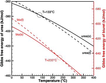 |
| | Fig. 1 Gibbs free energy of urea and biuret. | |
The authors want to give a thermodynamic explanation for this observation. It can be explained by considering a eutectic mixture of urea and biuret. For varying mole fraction, we can plot the temperatures, where
| | μ0i(s) = μ0i(l) + RT![[thin space (1/6-em)]](https://www.rsc.org/images/entities/char_2009.gif) ln(Xi(l)). ln(Xi(l)). | (29) |
Fig. 2 shows the phase diagram of the binary urea/biuret system. It agrees well with the results reported by Voskov
et al.39 This means that biuret is a liquid at 193 °C if the liquid phase consists of 67% biuret and 33% urea. As decomposition or evaporation of urea becomes faster at temperatures above 210 °C, biuret will become solid again. As we will see later, there is another thermodynamic argument for the apparent melting point of biuret.
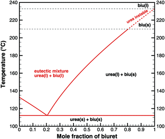 |
| | Fig. 2 Phase diagram of a eutectic mixture of urea and biuret. | |
This interpretation yields a qualitative understanding of experimental DSC data for urea and biuret. Fig. 3 shows a comparison of the DSC signals. Together with the TG data, we can identify several processes. The sharp peak at 133 °C indicates the melting of urea. The decomposition of urea starts more or less with the phase change. Biuret as a reaction product will remain in the liquid phase. At 193 °C, the decomposition process also starts for biuret. The reaction slows down at around 210 °C, when a foam-like structure is formed. Presumably, there is no liquid urea present anymore. Endothermic reactions may lead to follow-up products like triuret, cyanuric acid or ammelide. Around 230 °C, biuret becomes liquid again and a second decomposition step is observable in TG measurements. The third decomposition step between 330 and 400 °C is associated with the sublimation of cyanuric acid. The remaining solid substances decompose at temperatures above 400 °C, for which we include a reaction path involving ammelide, but this shall not be the focus of this paper.
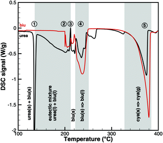 |
| | Fig. 3 Qualitative comparison of DSC signals for urea and biuret decomposition (1 – melting of urea, 2 – melting of biuret in a eutectic mixture, 3 – urea disappears, 4 – melting of biuret, and 5 – sublimation of cyanuric acid). | |
5 Reaction mechanism
Cyanuric acid
In Brack's model,13 cyanuric acid decomposes directly to isocyanic acid (cya(s) → 3HNCO(g)) through a zeroth order reaction. In order to investigate this hypothesis, TG and DSC experiments were run with pure cyanuric acid as an initial sample. The TG experiment (Fig. 4) was conducted using two crucibles with different diameters. If the reaction was a zeroth order reaction in the homogeneous phase, the size of the crucible would not matter. However, the reaction is faster in a flat crucible with a larger surface area than in a tall crucible. This suggests that the reaction takes place at the surface of the sample. Indeed, both TG curves can be modeled by using a first-order surface reaction with an activation energy of 141.3 kJ mol−1. However, this immediately raises the question about the resulting products, because the direct decomposition to isocyanic acid is an endothermic process consuming 352 kJ mol−1. A comparison between experimental and expected DSC signals (Fig. 5) shows that for a direct decomposition, the DSC signal should be larger by a factor of 2.5. The activation energy obviously agrees with the heat of sublimation of cyanuric acid. Therefore, it must be concluded that cyanuric acid evaporates directly into the gas-phase.| | | cya(s) → cya(g) ΔH = 141.3 kJ mol−1 | (30) |
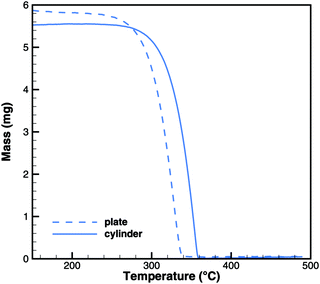 |
| | Fig. 4 Experimental TG data for the decomposition of cyanuric acid in cylinder (diameter 6 mm) and plate-type (15 mm) crucibles. | |
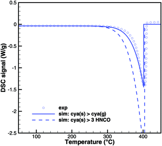 |
| | Fig. 5 Comparison of DSC signals of decomposition of cyanuric acid (model 1: sublimation and model 2: direct decomposition to isocyanic acid). | |
Triuret
In the previous mechanism put forth by Brack,13 triuret was a side product of biuret reacting with isocyanic acid. It could have been omitted without significantly changing the predicted amounts of cyanuric acid or ammelide. Looking at the chemical structures of the latter two, there is a good argument that triuret may decompose to cyanuric acid by separation of ammonia and to ammelide by separation of water. Thus, instead of going directly from biuret to cyanuric acid and ammelide by complex multi-molecule reactions, we may assume that triuret is an intermediate species of these processes.
Fig. 6 and 7 show a comparison of experimental TG and DSC data for biuret and triuret. It can be noted that there are parallels in the decomposition steps for both substances. A major decomposition step is observed for temperatures above 192 °C. The mass loss is mainly due to the release of isocyanic acid and ammonia. For biuret, as stated before, a second decomposition step appears at around 235 °C. This is not present for triuret. The possible reactions to cyanuric acid and ammelide would both yield a mass loss of about 12% and almost no heat signal of 8 and 22 kJ mol−1, respectively. The decomposition step beyond 260 °C can mainly be associated with the sublimation of cyanuric acid. A shift in temperature can be observed with respect to the decomposition steps of both experiments. This is attributed to the difference of the initial sample mass.
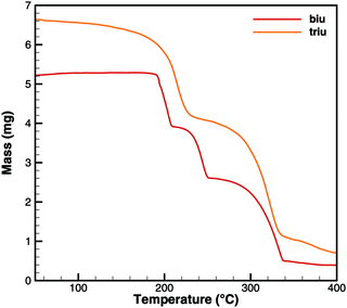 |
| | Fig. 6 Experimental TG data for decomposition of biuret and triuret. | |
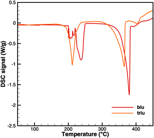 |
| | Fig. 7 Experimental DSC data for decomposition of biuret and triuret. | |
Triuret is a highly unstable substance. The TG data (Fig. 6) already show a mass loss for temperatures below 192 °C. Since there is no significant DSC signal (besides the heat capacity of triuret) at these low temperatures, the mass loss might have been due to kinetically limited reactions to isocyanic acid or ammelide, which are almost isoenthalpic. However, all fits of kinetic parameters over-predicted the produced amounts of these two products for higher temperatures. Therefore, it was concluded that the underlying process is a thermodynamically controlled equilibrium. Using the program DETCHEMEQUIL,15 equilibrium calculations for an ensemble consisting of urea(s), urea(l), biu(s), biu(l), triu(s), HNCO(l), HNCO(g) and N2 were carried out. According to the literature data (Table 2), triuret would have remained stable up to 192 °C. However, the literature data for triuret are very insufficient. Thus, we tried to reverse-engineer thermodynamic data for triuret, by fitting the values of the Gibbs free energy of triuret in such a way that the calculated equilibrium composition shows the same mass loss (due to the release of HNCO(g)) as the TG experiment (Fig. 6). The calculation becomes sensitive to the dilution of HNCO(g) by an inert gas (e.g., N2). Fig. 8 shows the results of the fitting for varying degrees of dilution. For the calculation of thermodynamic coefficients for triu(s), we have chosen a dilution of 90%, i.e., the initial mixture consisted of 1 mol of triuret and 9 mol of N2. As a result, we get the standard enthalpy of formation ΔfH = −708.9![[thin space (1/6-em)]](https://www.rsc.org/images/entities/char_2009.gif) kJ mol−1 and standard entropy S⊖ = 359.1 J mol−1 K−1. The molar heat capacity was kept constant at cp = 131.3 J mol−1 K−1.
kJ mol−1 and standard entropy S⊖ = 359.1 J mol−1 K−1. The molar heat capacity was kept constant at cp = 131.3 J mol−1 K−1.
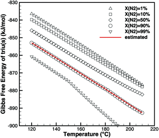 |
| | Fig. 8 Fitting of thermodynamic data of triuret such that equilibrium calculations yield the same mass loss as TG experiments. | |
Biuret
As seen for triuret, we cannot look at the decomposition of one substance independently. One always has to keep in mind the thermodynamic ensemble consisting of isocyanic acid, urea, biuret and triuret. In order to better understand the processes of biuret decomposition for temperatures between 193 and 210 °C, we conducted TG experiments where biuret was heated up to 195, 200 and 210 °C, respectively. Initially, a constant temperature ramp of 2 K min−1 was applied. After reaching the target temperature, it was kept constant. Fig. 9 shows the result for the case of 195 °C.
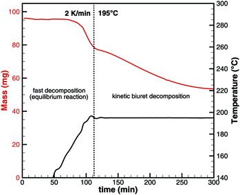 |
| | Fig. 9 Experimental TG data for biuret that was first heated to 195 °C with a constant heating ramp and then temperature was kept constant. | |
For this sample, decomposition already starts below 193 °C. The most notable feature of this graph is that its slope is larger for the temperature ramp than for the case of constant temperature. This indicates that the decomposition is not only kinetically controlled. Otherwise, the reaction rate (and thus the slope of the graph) should be lower for lower temperatures. Therefore, again, the mass loss during the temperature ramp is dominated by thermodynamic equilibrium processes. A fact that is not well taken into account in experiment design is that this equilibrium depends on the dilution of HNCO(g) in the gas phase. Thus, the decomposition of biuret may start at temperatures as low as 170 °C for high purging rates with inert gas. On the other hand, if we calculate the equilibrium composition based on a lower dilution for an initial mixture of 1 mol of biuret and 1 mol of nitrogen using DETCHEMEQUIL,15 we get a surprisingly nice result (Fig. 10). Here, we see a phase change at 192.5 °C when a eutectic mixture of liquid biuret and urea plus some triuret and gaseous isocyanic acid becomes thermodynamically favored. This explains the apparent melting point of biuret in the literature.
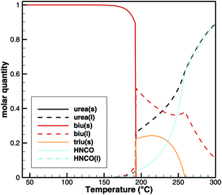 |
| | Fig. 10 Equilibrium composition of an initial mixture of 1 mol of biuret and 1 mol of N2. | |
Urea
Finally, we need to look at the initiation of urea decomposition, which starts with melting at 132 °C. Fig. 11 shows the measured TG and DSC data. Between 140 and 180 °C, the apparent reaction rate increases nearly linearly. According to the Brack mechanism,13 this is mainly due to the reaction urea(l) → HNCO(l) + NH3(g). At this temperature, the vapor pressure of isocyanic acid is already more than 26 bar according to eqn (20). Unless HNCO(l) reacts very fast to form biuret or triuret, it would evaporate, leaving no caloric contribution of HNCO(l) in a DSC experiment. A direct decomposition would lead to a net reaction| | | urea(l) → HNCO(g) + NH3(g) ΔRH(160 °C) = 153.8 kJ mol−1. | (31) |
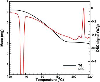 |
| | Fig. 11 Comparison of TG and DSC data for the initiation of urea decomposition. | |
According to Fig. 11, we have a mass loss of 2.25 mg (3.75 × 10⁻⁵ mol urea) for the temperature interval of 140–180 °C. The DSC signal increases nearly linearly from 0.13 to 0.375 W g−1 within 20 min. This accounts for a total heat consumption of 1.87 J. However, the direct decomposition would have required 5.77 J. All numerical simulations involving a direct decomposition reaction showed that TG and DSC signals could not be satisfied at the same time. They differed by a factor of 3. Thus, we had to discard the direct decomposition reaction.
Several ideas have been tried to initiate urea decomposition. Since the rate is sensitive to the size of the crucible, it was concluded that the process occurs at the gas–liquid interface. The net reaction that best fitted both the DSC and the TG data in the interval of 140–180 °C was
| | | 2urea(l) → biu(l) + NH3(g) ΔRH = 55.6 kJ mol−1 | (32) |
as also recently suggested by Wang
et al.14
Kinetic parameters
As a result of the aforementioned investigations, the authors came up with the following reaction scheme (see Fig. 12): urea decomposition is mainly driven by a thermodynamic equilibrium in the system consisting of urea, biuret, triuret and isocyanic acid. Ammonia is produced by a kinetically limited process with the net reaction 2urea(l) → biu(l) + NH3(g). In analogy, a reaction to form triuret has been added: biu(l) + urea(l) → triu(s) + NH3(g). Triuret then reacts further to form solid deposits of cyanuric acid and ammelide. Cyanuric acid sublimates at temperatures above 300 °C. This process is described here by a non-reversible surface process. However, it would make sense to describe it as an equilibrium process if reliable thermodynamic data for solid cyanuric acid were available. For the sake of completeness, 6 global reaction steps for the decomposition of ammelide were added (see the ESI†).
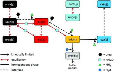 |
| | Fig. 12 Proposed reaction scheme of urea decomposition. | |
The kinetic parameters were adjusted manually until the main features of DSC and TG experiments were satisfied. A following automated parameter optimization did not significantly improve the results. Therefore, we use the manually fitted parameters for this publication (Table 3) in order to avoid pretending a higher precision of the kinetic parameters. The biggest uncertainty is still the thermodynamic data of biuret and triuret.
Table 3 Kinetic parameters of the proposed reaction scheme of urea decomposition (see also Appendix C in the ESI)
| Reaction |
A
k
(in SI units) |
β
k
|
E
a,k (in kJ mol−1) |
Notes |
| Homogeneous phase |
| urea(l) + HNCO(l) ⇌ biu(s) |
1 × 10⁻⁴ |
0 |
0 |
These three reactions feature HNCO(l) even though the net product of the reverse reaction is HNCO(g). |
| urea(l) + HNCO(l) ⇌ biu(l) |
1 × 10⁻⁴ |
0 |
0 |
| biu(l) + HNCO(l) ⇌ triu(s) |
1 × 10⁻⁴ |
0 |
0 |
| triu(s) → cya(s) + NH3(g) |
1.2 × 10² |
0 |
45 |
| triu(s) → ammd(s) + H2O(g) |
3 × 101 |
0 |
45 |
| Surface |
| 2 urea(l) → biu(l) + NH3(g) |
3.5 × 100 |
0 |
99 |
|
| biu(l) + urea(l) → triu(s) + NH3(g) |
2 × 10² |
0 |
116.5 |
|
| cya(s) → cya(g) |
3 × 10⁴ |
0 |
141.3 |
|
| Phase change (surface) |
| H2O(g) ⇌ H2O(l) |
8.6 × 10⁻² |
0.5 |
0 |
The condensation–evaporation equilibria are based on the Hertz–Knudsen model (eqn (11)). |
| urea(g) ⇌ urea(l) |
4.7 × 10⁻² |
0.5 |
0 |
| HNCO(g) ⇌ HNCO(l) |
5.5 × 10⁻² |
0.5 |
0 |
| urea(l) ⇌ urea(s) |
1 × 10⁻⁶ |
0 |
0 |
Adjusted to DSC signals of urea melting. |
| biu(l) ⇌ biu(s) |
1 × 10⁻⁶ |
0 |
0 |
6 Simulation results
The quality of the proposed reaction mechanism can be evaluated by comparison of the experimental data with the simulation results. Here, we will give results for some of the experiments listed in Table 1. The other cases will be shown in the ESI.†
One of the consequences of the equilibrium processes involving isocyanic acid is that the model becomes sensitive to the gas-phase concentration of HNCO(g). This was not taken into account during reactor model development when a zero-dimensional approach was chosen to describe TG experiments. The concentration gradient in the gas phase should be modeled as well. To guarantee a sufficient dilution of the evaporating HNCO(g), the gas-phase volume was assumed to be a cylinder with the diameter of the crucible and a height of 2 m.
Cyanuric acid
The experiments with cyanuric acid are well modeled by the sublimation reaction. The DSC signal (Fig. 13) and TG data (Fig. 14) show good agreement. For the plate-type crucible, the sublimation is shifted correctly by ca. 40 K to lower temperatures. In reality, the dependency on the diameter of the crucible is less pronounced than in the simulation, because the surface area of the solid sample does not decrease linearly with the size of the crucible. However, if the model is applied to thin layers of deposits of cyanuric acid, it should be valid that the rate of sublimation is proportional to the size of the deposit.
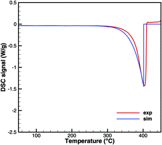 |
| | Fig. 13 DSC data of cyanuric acid (cylinder crucible). | |
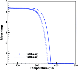 |
| | Fig. 14 TG data of cyanuric acid (cylinder crucible, 2 K min−1) with simulated composition of the mixture. | |
Triuret
A comparison of experimental data and simulation results for triuret decomposition is shown in Fig. 15 and 16. In both diagrams, two main decomposition steps can be identified: a step involving biuret at temperature between 190 and 230 °C and the sublimation of cyanuric acid. The simulation broadens the first step to lower temperatures. This is because the TG data up to 200 °C have been used to adjust the thermodynamic data of triuret on the assumption of an equilibrium in the urea–biuret–triuret–HNCO ensemble. However, this does not account for the mass loss due to the kinetically limited reactions that release ammonia. Therefore, the total mass loss using the full mechanism is overestimated and shifted to lower temperatures. Here, a better agreement could only be achieved by improving the thermodynamic data of biuret and triuret.
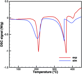 |
| | Fig. 15 DSC data of triuret (cylinder crucible). | |
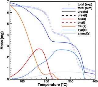 |
| | Fig. 16 TG data of triuret (cylinder crucible, 2 K min−1) with simulated composition of the mixture. | |
The simulation of TG experiments (Fig. 16) also gives an insight into the composition of the mixture in the crucible. No significant amounts of liquid urea seem to be formed. Therefore, biuret also stays solid until complete decomposition at around 230 °C. Since the first decomposition step is slightly overestimated, the amount of cyanuric acid is then underestimated. Ammelide formation is matched well when assuming that production of cyanuric acid and ammelide is in the ratio of 4![[thin space (1/6-em)]](https://www.rsc.org/images/entities/char_2009.gif) :
:![[thin space (1/6-em)]](https://www.rsc.org/images/entities/char_2009.gif) 1. The TG results show even better agreement for a temperature ramp of 10 K min−1 because thermodynamically controlled equilibrium processes are more dominant than kinetically controlled reactions.
1. The TG results show even better agreement for a temperature ramp of 10 K min−1 because thermodynamically controlled equilibrium processes are more dominant than kinetically controlled reactions.
Biuret
Unfortunately, no good agreement could yet be achieved for biuret (Fig. 17 and 18). The interplay of thermodynamics and reaction kinetics does not resolve the effects in Fig. 3. There should be three decomposition steps: the eutectic urea–biuret phase, the biuret–triuret phase and the sublimation of cyanuric acid. For the same reason why triuret decomposition is overestimated at lower temperatures, triuret production is now underestimated in the first reaction step. Thus, triuret decomposition does not contribute much to the TG signal in the simulation, even though triuret is present in the expected temperature range of 210–230 °C. Here, thermodynamic data should shift the equilibrium of urea–biuret–triuret–HNCO towards triuret. Better agreement was achieved for the 10 K min−1 experiment when decomposition is shifted to higher temperatures and the two decomposition steps also merge in reality.
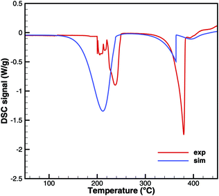 |
| | Fig. 17 DSC data of biuret (cylinder crucible). | |
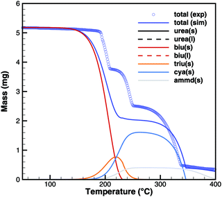 |
| | Fig. 18 TG data of biuret (cylinder crucible, 2 K min−1) with simulated composition of the mixture. | |
On the other hand, simulations of TG experiments with biuret where heating was stopped at 195, 200 and 210 °C show very good agreement (Fig. 19). It should be noted that these experiments used a 15 times higher initial mass of biuret. Thus, the contribution of volumetric equilibrium reactions is increased over the ammonia producing surface reactions.
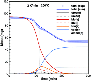 |
| | Fig. 19 TG data of biuret maintaining a constant temperature of 200 °C. | |
Urea
For practical simulations of SCR systems, we are mainly interested in the deposits resulting from urea decomposition. Here, the situation looks better than for biuret. Experiments show three decomposition steps: a step in the liquid urea–biuret mixture, a biuret–triuret step and the sublimation of cyanuric acid. The initiation of the decomposition is well matched in DSC and TG data (Fig. 20 and 21). The biuret–triuret step occuring in simulation again shifted to lower temperatures, but there is a phase change at around 200 °C, when all urea is consumed. The produced amounts of biuret and triuret seem to be in the right order of magnitude, leading to correct predictions for cyanuric acid and ammelide. The predicted results again become even better for the 10 K min−1 ramp, when the first and the second decomposition steps also merge in the experiment.
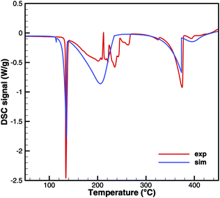 |
| | Fig. 20 DSC data of urea (cylinder crucible). | |
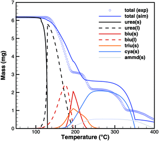 |
| | Fig. 21 TG data of urea (cylinder crucible, 2 K min−1) with simulated composition of the mixture. | |
7 Conclusions
At a first glance, there still seems to be too much uncertainty. The previous mechanism put forth by Brack et al.13 was able to model the three decomposition steps of urea at the right temperature intervals. However, the proposed reaction scheme is advantageous in several ways:
First, it is stringently based on thermodynamics. Melting and solidification of substances are inherent to the thermodynamic data. The phase change during biuret decomposition can be explained by the formation of a eutectic mixture. There is no need for an extra matrix species.
Second, it is consistent with DSC experiments. From these, we can conclude that cyanuric acid does not decompose to isocyanic acid directly, but it sublimates instead. Furthermore, we can also rule out the direct decomposition of urea to gaseous ammonia and isocyanic acid.
Third, it scales correctly with crucible size and the gradient of the temperature ramp. Thus, we have to distinguish between processes that are controlled by thermodynamic equilibrium and kinetically controlled surface reactions.
Last, but not least, the overall reaction scheme is much simpler. In the tradition of Occam's razor, it explains more effects with less assumptions compared to the Brack mechanism.
The reaction mechanism is not perfect yet. The main reason is the lack of data for the thermodynamic potentials of biuret and triuret. Eventually, a liquid triuret species should be added, because it should be part of the eutectic mixture. Currently, triuret decomposition is shifted to lower temperatures. This causes a coincidence of the first and second decomposition step for biuret.
For urea decomposition, the results are in good agreement with the measurements reported by Wang et al.14 The dominant process for biuret and triuret formation is the self-combination of urea, which leads to the desorption of ammonia. However, this is a bit unsatisfying from the viewpoint of elementary reaction step mechanisms. According to the DSC signal, this reaction step cannot involve HNCO(l). A more elegant explanation might be a route through an ionic reaction such as urea → NH4+ + OCN−, as suggested by Kieke et al.40
To summarize, the authors propose a new reaction mechanism for urea decomposition, which is closer to the real processes than the previously published mechanisms. We want to emphasize the importance of thermodynamics in modeling deposit formation in SCR systems.
Nomenclature
|
A
| Cross-sectional area of the crucible (m2) |
|
A
k
| Pre-exponential factor (mol m−3 s−1 or mol m−2 s−1) |
|
a
i
| Chemical activity coefficient (−) |
|
a
ni
| Coefficient of NASA polynomials |
|
c
i
| Concentration (mol m−3) |
|
c
⊖
i
| Reference concentration at normal pressure (mol m−3) |
|
c
p,i
| Molar heat capacity (J mol−1 K−1) |
|
E
a,k
| Activation energy (J mol−1) |
|
H
| Enthalpy (J) |
|
H
m,I
| Molar enthalpy (J mol−1) |
|
h
| Henry constant (−) |
|
K
c,k
| Equilibrium constant in terms of concentrations (variable units) |
|
K
p,k
| Equilibrium constant (−) |
|
K
H
| Henry's coefficient (mol m−3 Pa−1) |
|
k
W
| Heat transfer coefficient (W m−2 K−1) |
|
M
i
| Molar mass (kg mol−1) |
|
m
| Mass (kg) |
|
n
i
| Molar amount (mol) |
|
ṅ
ik
| Molar rate of species Si by reaction Rk (mol s−1) |
|
P
j
| Phase |
|
P
DSC
| DSC signal (W) |
|
p
| Pressure (Pa) |
|
p
⊖
| Standard pressure (101![[thin space (1/6-em)]](https://www.rsc.org/images/entities/char_2009.gif) 325 Pa) 325 Pa) |
|
p
i
| Partial pressure (Pa) |
|
p
vap
i
| Vapour pressure (Pa) |
|
R
| Gas constant (8.31446 J mol−1 K−1) |
|
R
k
| Reaction |
|
r
k
| Molar rate of reaction (mol m−3 s−1 or mol m−2 s−1) |
|
S
i
| Species |
|
S
⊖
| Standard entropy at 298.15 K (J mol−1 K−1) |
|
S
m,i
| Molar entropy (J mol−1 K−1) |
|
T
| Temperature (K) |
|
T
⊖
| Standard temperature (298.15 K) |
|
t
| Time (s) |
|
V
j
| Volume of phase Pj (m3) |
|
V
m,i
| Molar volume (m3 mol−1) |
|
X
i
| Mol fraction (−) |
|
Y
i
| Mass fraction (−) |
|
α
c
| Accumulation factor for condensation (−) |
|
β
k
| Temperature exponent |
| ΔRkG⊖ | Reaction free enthalpy (J mol−1) |
| ΔfH⊖ | Standard enthalpy of formation at 298.15 K (J mol−1) |
| ΔsolH⊖ | Standard enthalpy of solution at 298.15 K (J mol−1) |
|
μ
i
| Chemical potential of species (J mol−1) |
|
μ
0
i
| Chemical potential of undiluted species (J mol−1) |
|
ν
ik
| Stoichiometric coefficient |
![[small nu, Greek, tilde]](https://www.rsc.org/images/entities/i_char_e0e1.gif) ik
ik
| Concentration exponent |
|
ρ
I
| Density (kg m−3) |
Conflicts of interest
There are no conflicts to declare.
Acknowledgements
The authors kindly acknowledge the financial support from the German Research Foundation (Deutsche Forschungsgemeinschaft, DFG) through project 237267381 – TRR 150. DFG is also acknowledged for financing the thermogravimetrical analysis equipment within project INST 121384/70-1. Furthermore, we acknowledge Steinbeis GmbH & Co. KG für Technologietransfer (STZ 240 Reaktive Strömung) for a cost-free license of DETCHEM.
References
- Regulation (EC) No 715/2007 of the European Parliament and of the Council of 20 June 2007 on type approval of motor vehicles with respect to emissions from light passenger and commercial vehicles (Euro 5 and Euro 6) and on access to vehicle repair and maintenance information (Text with EEA relevance), 2007, http://data.europa.eu/eli/reg/2007/715/oj.
- F. Birkhold, U. Meingast, P. Wassermann and O. Deutschmann, Appl. Catal., B, 2007, 70, 119–127 CrossRef CAS.
- M. Börnhorst and O. Deutschmann, Int. J. Heat Fluid Flow, 2018, 69, 55–61 CrossRef.
- M. Börnhorst, S. Langheck, H. Weickenmeier, C. Dem, R. Suntz and O. Deutschmann, Chem. Eng. J., 2018 DOI:10.1016/j.cej.2018.09.016.
- L. Stradella and M. Argentero, Thermochim. Acta, 1993, 219, 315–323 CrossRef CAS.
- A. G. Koryakin, V. A. Gal'perin, A. N. Sarbaev and A. I. Finkel'shtein, Zh. Org. Khim., 1971, 972–977 CAS.
- H. L. Fang and H. F. M. DaCosta, Appl. Catal., B, 2003, 46, 17–34 CrossRef CAS.
- P. M. Schaber, J. Colson, S. Higgins, D. Thielen, B. Anspach and J. Brauer, Thermochim. Acta, 2004, 424, 131–142 CrossRef CAS.
- A. Lundström, B. Andersson and L. Olsson, Chem. Eng. J., 2009, 150, 544–550 CrossRef.
- M. Eichelbaum, R. J. Farrauto and M. J. Castaldi, Appl. Catal., B, 2010, 97, 90–97 CrossRef CAS.
- A. M. Bernhard, D. Peitz, M. Elsener, A. Wokaun and O. Kröcher, Appl. Catal., B, 2012, 115–116, 129–137 CrossRef CAS.
- V. Ebrahimian, A. Nicolle and C. Habchi, AIChE J., 2012, 58, 1998–2009 CrossRef CAS.
- W. Brack, B. Heine, F. Birkhold, M. Kruse, G. Schoch, S. Tischer and O. Deutschmann, Chem. Eng. Sci., 2014, 106, 1–8 CrossRef CAS.
- D. Wang, N. Dong, S. Hui and Y. Niu, Fuel, 2019, 242, 62–67 CrossRef CAS.
-
O. Deutschmann, S. Tischer, S. Kleditzsch, V. Janardhanan, C. Correa, D. Chatterjee, N. Mladenov, H. D. Minh, H. Karadeniz, M. Hettel, V. Menon and A. Banerjee, DETCHEM Software package, 2.7 ed., 2018, http://www.detchem.com Search PubMed.
-
A. Burcat, Burcat's Thermodynamic Data, http://garfield.chem.elte.hu/Burcat/burcat.html.
- T. Huthwelker and T. Peter, J. Chem. Phys., 1996, 105, 1661–1667 CrossRef CAS.
- P. Deuflhard, E. Hairer and J. Zugck, Numer. Math., 1987, 51, 501–516 CrossRef.
-
A. Roine, Outokumpu HSC Chemistry for Windows Chemical Reaction and Equilibrium Software with Extensive Thermochemical Database, 2002 Search PubMed.
- G. Y. Kabo, E. A. Miroshnichenko, M. L. Frenkel, A. A. Kozyro, V. V. Simirskii, A. Krasulin, V. Vorob'eva and Y. Lebedev, Bull. Acad. Sci. USSR, Div. Chem. Sci., 1990, 662–667 CrossRef.
-
http://webbook.nist.gov/
.
- A. A. Kozyro, M. L. Frenkel, A. P. Krasulin, V. V. Simirskii and G. Y. Kabo, Zh. Fiz. Khim., 1988, 62, 1752–1756 CAS.
- R. C. Mann and C. K. Frederig, J. Chem. Soc., 1943, 603–606 Search PubMed.
- A. A. Kozyro, G. Y. Kabo, T. V. Soldatova, V. V. Simirskii, V. I. Gogolinskii, A. P. Krasulin and N. M. Dudarevich, Zh. Fiz. Khim., 1992, 66, 2583–2590 CAS.
- H. G. M. DeWit, C. G. DeKruif and J. C. Van Miltenburg, J. Chem. Thermodyn., 1983, 15, 891–902 CrossRef CAS.
- V. D. Selivanov, V. M. Karlik and V. I. Zagranicnyi, Russ. J. Phys. Chem., 1973, 47, 476–477 CAS.
- D. Gratzfeld and M. Olzmann, Chem. Phys. Lett., 2017, 619, 219–224 CrossRef.
- M. Linhard, Z. Anorg. Allg. Chem., 1938, 236, 200–208 CrossRef CAS.
- C. L. Speyers, Am. J. Sci., 1902, 14, 293–302 CrossRef CAS.
- L. A. Pinck and M. A. Kelly, J. Am. Chem. Soc., 1925, 47, 2170–2172 CrossRef CAS.
- F.-M. Lee and L. E. Lahti, J. Chem. Eng. Data, 1972, 17, 304–306 CrossRef CAS.
-
VDI-Wärmeatlas: mit 320 Tabellen, ed. VDI, Springer Vieweg, Berlin, Heidelberg, 11th edn, 2013 Search PubMed.
-
Lange's Handbook of chemistry, ed. J. A. Dean and N. A. Lange, McGraw-Hill, New York, 13th edn, 1985 Search PubMed.
-
Kaye and Laby, Tables of Physical & Chemical Constants (16th edition 1995). 3.2 Properties of inorganic compounds. Version 1.0 (2005), Kaye & Laby Online, 2005 Search PubMed.
- ICSC Database – International Labour Organisation, 2017, http://www.ilo.org/safework/info/publications/WCMS_113134/lang-en/index.htm.
- F. L. Smith and A. H. Harvey, Chem. Eng. Prog., 2007, 103, 33–39 CAS.
- N. Borduas, B. Place, G. R. Wentworth, J. P. D. Abbatt and J. G. Murphy, Atmos. Chem. Phys., 2016, 16, 703–714 CrossRef CAS.
-
http://roempp.thieme.de/
.
- A. I. Voskov, T. S. Babkina, A. V. Kuznetsov and I. A. Uspenskaya, J. Chem. Eng. Data, 2012, 57, 3225–3232 CrossRef CAS.
- M. L. Kieke, J. W. Schoppelrei and T. B. Brill, J. Phys. Chem., 1996, 100, 7455–7462 CrossRef CAS.
Footnote |
| † Electronic supplementary information (ESI) available. See DOI: 10.1039/c9cp01529a |
|
| This journal is © the Owner Societies 2019 |
Click here to see how this site uses Cookies. View our privacy policy here.  Open Access Article
 *a,
Marion
Börnhorst
 b,
Jonas
Amsler
 b,
Günter
Schoch
b and
Olaf
Deutschmann
 ab
ab


![[thin space (1/6-em)]](https://www.rsc.org/images/entities/char_2009.gif) ln(Xurea(aq)) = μ0urea(s)
ln(Xurea(aq)) = μ0urea(s)![[thin space (1/6-em)]](https://www.rsc.org/images/entities/char_2009.gif) ln(Xurea(aq))
ln(Xurea(aq))
![[thin space (1/6-em)]](https://www.rsc.org/images/entities/char_2009.gif) ln(Xi(aq))
ln(Xi(aq))

![[thin space (1/6-em)]](https://www.rsc.org/images/entities/char_2009.gif) ln(Xi(l)).
ln(Xi(l)).

![[thin space (1/6-em)]](https://www.rsc.org/images/entities/char_2009.gif) kJ mol−1 and standard entropy S⊖ = 359.1 J mol−1 K−1. The molar heat capacity was kept constant at cp = 131.3 J mol−1 K−1.
kJ mol−1 and standard entropy S⊖ = 359.1 J mol−1 K−1. The molar heat capacity was kept constant at cp = 131.3 J mol−1 K−1.


![[thin space (1/6-em)]](https://www.rsc.org/images/entities/char_2009.gif) :
:![[thin space (1/6-em)]](https://www.rsc.org/images/entities/char_2009.gif) 1. The TG results show even better agreement for a temperature ramp of 10 K min−1 because thermodynamically controlled equilibrium processes are more dominant than kinetically controlled reactions.
1. The TG results show even better agreement for a temperature ramp of 10 K min−1 because thermodynamically controlled equilibrium processes are more dominant than kinetically controlled reactions.![[thin space (1/6-em)]](https://www.rsc.org/images/entities/char_2009.gif) 325 Pa)
325 Pa)![[small nu, Greek, tilde]](https://www.rsc.org/images/entities/i_char_e0e1.gif) ik
ik


