
 Open Access Article
 This Open Access Article is licensed under a Creative Commons Attribution-Non Commercial 3.0 Unported Licence
Plasma-assisted catalytic formation of ammonia in N2–H2 plasma on a tungsten surface†
Marwa
Ben Yaala
 *a,
Arsalan
Saeedi
a,
Dan-Felix
Scherrer
a,
Lucas
Moser
a,
Roland
Steiner
a,
Marco
Zutter
a,
Martin
Oberkofler
b,
Gregory
De Temmerman
c,
Laurent
Marot
a and
Ernst
Meyer
a
*a,
Arsalan
Saeedi
a,
Dan-Felix
Scherrer
a,
Lucas
Moser
a,
Roland
Steiner
a,
Marco
Zutter
a,
Martin
Oberkofler
b,
Gregory
De Temmerman
c,
Laurent
Marot
a and
Ernst
Meyer
a
aDepartment of Physics, University of Basel, Klingelbergstrasse 82, CH-4056 Basel, Switzerland. E-mail: marwa.benyaala@unibas.ch; Tel: +41 61 207 3727
bMax Planck Institute for Plasma Physics, Boltzmannstrasse 2, 85748 Garching, Germany
cITER Organization, Route de Vinon-sur-Verdon, CS 90 046, 13067 St Paul Lez Durance Cedex, France
First published on 12th July 2019
Abstract
Plasma catalysis has drawn attention in the past few decades as a possible alternative to the Haber–Bosch process for ammonia production. In particular, radio frequency plasma assisted catalysis has the advantage of its adaptability to the industrial scale. However, in the past years, very few experimental studies have focused on the synthesis of ammonia from nitrogen/hydrogen radio frequency plasma. As a consequence, to date, there has been little agreement about the complex mechanisms underlying the radio frequency plasma-catalyst interactions. Gaining such an understanding is therefore essential for exploiting the potential of radio frequency plasma catalysis for ammonia production. In this study, we present results of ammonia formation from a nitrogen/hydrogen radio frequency plasma both without and with a tungsten catalyst for different initial nitrogen ratios. High yields of ammonia up to 32% at 25/75% of nitrogen/hydrogen were obtained using a combination of radio frequency low pressure plasma and a W surface as a catalyst. Furthermore, based on chemical analysis of the catalytic surface composition, a formation pathway of ammonia via the Eley–Rideal mechanism between adsorbed nitrogen and hydrogen from the gas phase is presented.
1 Introduction
The synthesis of ammonia (NH3) from its elements (N2 and H2) is often considered as one of the most important discoveries in the history of the science of catalysis, in large part because of its industrial application in the production of synthetic fertilizers which contributed enormously to the sustainment of mankind's population. It is often referred to as the most important invention of the 20th century.1 Besides its agricultural applications, ammonia is used to produce plastics, synthetic fibers and resins, explosives, and numerous chemical compounds and has also potential applications as an indirect hydrogen storage material or as a fuel for fuel cells.2Ammonia production is also a concern for a specific project that aims to harvest energy from nuclear fusion. Fusion has been developed for several decades in various countries in the world as a proposed new source of energy for mankind, and these efforts have culminated with the ITER project currently under construction in Southern France. However, one of the major challenges towards the development of commercial fusion reactors is the control of the interactions between the hot plasma and the surrounding materials. In fusion devices, extrinsic impurities are typically injected in the edge region of the confined plasma to help dissipate the intense power exhausting the plasma before it reaches nearby surfaces. Nitrogen is the preferred species for existing devices because of its beneficial effect on the plasma performances.3 In this context, ammonia formation resulting from fusion plasma and plasma facing components’ interaction with nitrogen gas is an increasingly important subject of research for the nuclear fusion community including ourselves over the past few years. Nitrogen injection leads to the formation of ammonia. The formation of tritiated ammonia in future fusion devices such as ITER may pose some issues with regards to tritium inventory and duty cycle. In the JET (Joint European Torus) 15% of the injected nitrogen was transformed into ammonia4 while in ASDEX Upgrade (Axially Symmetric Divertor Experiment), up to 8% of the injected N2 was also converted into NH3.5,6 In this context, a fundamental understanding of the plasma assisted ammonia formation process for a fusion reactor material would be the key both to predict the quantity of ammonia that might be formed in future fusion devices like ITER and to find possible ways to decrease it. Moreover, in fusion devices where the plasma-exposed area is a small fraction of the in-vessel surface area it is still unclear and poorly investigated where ammonia formation predominantly occurs and what effect the material surfaces have on the production.
Currently ammonia is produced from the reaction between N2 and H2via the Haber–Bosch process that was developed in 1913. The process requires high temperature (450–600 °C), very high pressures (140–350 bar) and the presence of a catalyst. These extreme reaction conditions make ammonia production the most energy intensive process in the chemical industry with a consumption of up to 2% of the world annual energy supply and generates 1% of its CO27 emissions. A new synthesis method for ammonia is therefore strongly desired from an energy saving perspective. Various alternatives including biochemical methods,8,9 catalytic pyrolysis,10,11 plasma catalysis12 and the development of innovative catalysts13 for thermal processing have been proposed.
Among the possible options, plasma catalysis has some significant advantages. The presence of reactive plasma species, such as electrons, ions, (excited) atoms, and radicals, enables efficient reaction even at room temperature and pressure below 1 bar. Plasma catalysis has thus the potential to provide improved energy efficiency, decreased capital costs, and extended catalyst lifetime.14 Over the years, the formation of ammonia from nitrogen and hydrogen feed gases has been studied for a wide variety of plasmas from high pressure thermal plasmas15–22 (lower electron and ion temperatures than in low-pressure plasmas but high gas temperature) to low pressure plasmas23–29 (high electron and ion energy).
For the low pressure plasmas (typically at 0.01 to 10 mbar of pressure), only few experimental studies were investigating the synthesis of ammonia from nitrogen–hydrogen using low pressure radio frequency (RF) discharges23,30–36 despite that RF sources are currently the most common plasma sources employed in the semiconductor industry37 and their use for ammonia plasma-assisted catalytic synthesis would have the advantage of adapting the process to the industrial scale. Moreover, RF plasma sources present the advantage of being less harmful than other sources in cases of radiation leakage and they have a longer lifetime as the RF coils are not in direct contact with the plasma and cannot therefore be etched.30
To our knowledge, the catalytic ammonia formation process from N2/H2 RF plasma is still not well understood and no general agreement on the dominant surface mechanism is established via previous experimental and computational studies. In particular, the understanding of the mechanism behind the NH3 formation through plasma catalysis would allow to control and tune its efficiency in a way to produce higher quantities for application in the chemical industry.
In the present article, we demonstrate experimentally the effect of the presence of a tungsten (a fusion relevant material) surface on ammonia production for different nitrogen hydrogen plasma compositions. A detailed description of a newly built setup, with the specificity of being just a quartz vacuum chamber (no metal), and the experimental procedure developed for studying the ammonia production will be presented. In addition, in another conventional stainless steel vacuum chamber, surface chemistry analyses were carried out using X-ray photoelectron spectroscopy (XPS). Fundamental information about the nature of the reactive processes occurring during RF plasma assisted ammonia synthesis will be presented.
2 Experimental section
2.1 Gas phase study in a metal-free vacuum chamber
As shown in our previous paper,38 ammonia molecules have a high sticking probability on metal surfaces and therefore measuring the production of ammonia in a standard stainless steel vacuum system would affect the measurement itself. Therefore, a new in-house built plasma reactor (Fig. 1) was used to perform experiments of NH3 synthesis from H2/N2 plasma.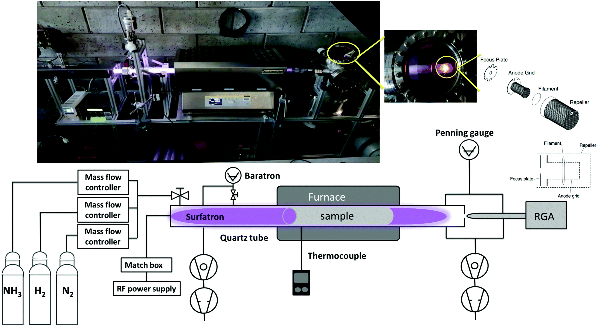 | ||
| Fig. 1 Schematic and real picture (on top) of the RF plasma reactor and surrounding equipment for gas inlet and outlet. | ||
This setup consists of a cylindrical quartz tube of 35 (31) mm outer (inner) diameter and 1405 mm length connected to a waveguide surfatron plasma source (350 mm length). The plasma is created in the tube through a matching network by a 13.56 MHz RF generator at a typical power of 120 W. Processing gases are introduced to the reaction chamber via the surfatron by mass flow controllers. The pressure is monitored by an MKS baratron capacitance manometer. Inside the tube a 50 × 10 cm2 rolled foil of the catalytic surface of choice (here tungsten with a purity of 99.97%) is placed and can be heated with a furnace up to a maximum temperature of 1000 °C. The ratio of the tungsten foil to the entire quartz surface is 1/3. The temperature is measured by a thermocouple placed in the outer wall of the quartz tube inside the furnace region. The W sample was at the floating potential and we verified experimentally by connecting the sample to the ground that the ammonia production does not depend on the sample potential.
On the other side of the quartz tube, a quadrupole mass spectrometer (SRS Residual Gas Analyser RG A200) is connected via a 2 mm diameter olyether ether ketone (PEEK) pinhole. A residual gas analyser is used for both qualitative and quantitative analyses of gas species resulting from the plasma. It ionizes, separates components of the gas to create various ions, and then detects and determines the mass-to-charge ratios. After passing the PEEK pinhole, gas molecules get accelerated to the ionizer of the RGA where positive ions are produced by electron-impact ionization. The main parts of the ionizer are: the repeller, the anode grid, the filament and the focus plate. In order to fully pump the NH3 from the RGA head between each experiment, the repeller, the anode grid and the focus plate (shown in Fig. 1) are coated with gold. The choice of the gold coating is based on a previous XPS study of ammonia sticking on metals38 showing a full desorption from a Au surface after pumping. In order to get a good background pressure of around 8 × 10⁻⁹ mbar in the RGA chamber (measured by a Penning gauge), the system is pumped from two sides through a turbo and a primary pump. However during the plasma process (typical pressure value of 5 × 10⁻⁶ mbar), gases are pumped only through the RGA chamber in order to detect all gas species.
To characterize the suitability of the system to quantify the ammonia production by avoiding the effect of the system storage over time, the chamber memory effect was tested by a set of two experiments described in the ESI.† Results show that the system storage for ammonia is very low and the degassing of the residual gas can be efficiently performed through an argon plasma.
A wall conditioning step using pure Ar plasma is carried out before each experiment followed by an RGA calibration procedure. It consists of determining the cracking patterns (CPs) and the calibration factors (CFs) for the different plasma species (N2, H2, NH3 and H2O). CFs represent the proportionality factor of the measured detected current in the RGA and its known partial pressure. CPs, on the other hand, represent the ratio between the major peak intensity and the other fragments’ intensity created by electron impact ionization in the RGA. Both the RGA calibration and chamber conditioning procedures are detailed in the ESI.†
Following the calibration step, the experiment was conducted by introducing nitrogen and hydrogen at different N2/H2 ratios set as:
 | (1) |
The plasma was then ignited for 5 to 10 min when no W sample was introduced in the tube and for 15 min in the presence of the sample. The choice of this time duration will be explained later in the Results section. The discharge zone is located in the quartz tube and the plasma is not in contact with any metallic surface before reaching the RGA head. All experiments were at room temperature (RT) and no additional heating was used for all experiments presented here although a temperature increase of about 20 °C was measured due only to thermal energy of the plasma. The nitrogen–hydrogen plasma can heat up the surfaces in contact with (including reactor wall and W sample) by the impact of charge carriers, photons, metastable and excited neutrals, and fast ground-state neutrals,39 and through exothermic surface reactions of ammonia synthesis. Product gases resulting from N2/H2 plasma were analysed continuously and spectra recorded every twenty seconds. All experiments were repeated at least twice and a reference experiment for an initial N2 concentration of 10% is repeated after each full cycle to ensure that the status of the W surface does not change over time.
For the deconvolution of the measured spectra, a Python code that takes into account the different compound CPs and CFs was employed. The concentrations of the different species are derived by fitting the height of the measured peaks to the sum of the cracking patterns of the species and the RGA currents are converted back to partial pressures using the CF of each species present.
2.2 Surface study in a conventional stainless steel vacuum chamber
In order to study and follow the formation mechanism of ammonia on a W surface, chemical analyses using XPS were performed to identify surface species formed after hydrogen and/or nitrogen plasma. Three different experiments were performed as follows: the exposure of a tungsten coated surface to N2/H2 plasma, then an exposure to pure N2 followed by pure H2 plasma and finally the exposure to pure H2 followed by N2 plasma. For each step a new fresh 20 nm tungsten film was deposited on silicon wafer by means of pulsed-DC magnetron sputtering of a 99.95% pure W target (details about the deposition parameters can be found in ref. 40).Both magnetron sputtering and nitrogen and/or hydrogen plasma exposure were performed in a stainless steel high vacuum system (described in ref. 41) with 5 × 10⁻⁸ mbar background pressure obtained using conventional pumping systems enhanced by a liquid nitrogen trap for selective trapping of residual gas. Following the deposition, the grounded W samples were exposed for 20 min to a N2 and/or H2 plasma generated with an external surfatron plasma source at a fixed total pressure of 1.2 × 10⁻² mbar.
Without breaking the vacuum, samples were transferred to an ultra-high vacuum chamber for XPS analysis. The typical time required for the sample transfer (i.e. time between when the plasma is stopped and the measurement is started) is around 15 to 30 min. The electron spectrometer is equipped with a hemispherical analyzer (Leybold EA10/100 MCD) and a non-monochromatized MgK X-ray source (hν = 1253.6 eV) was used for core level spectroscopy. The binding energy (BE) scale was calibrated using the Au 4f7/2 line of a cleaned gold sample at 84.0 eV. The fitting procedure of core level lines is described elsewhere.42
3 Results and discussion
3.1 Catalytic effect of the tungsten surface on ammonia formation studied by RGA in the metal free setup
The quantity of formed ammonia is shown in Fig. 2 where NH3 (%) is defined as the ratio of the partial pressure of the formed ammonia and the total pressure during the plasma. All experiments were repeated at least twice and the error bars presented in this figure represent the standard deviation of the measurements. Without catalyst, as the N2 fraction increases, the ammonia production increases up to 6% for an intial N2 fraction of 25% that corresponds to the stoichiometric composition of N2 and H2. This was observed in a N2/H2 microwave discharge in a Pyrex tube by Uyama and Matsumoto23 and in a DC glow discharge by Amorim et al.43 Yet, it is not clear if the production of ammonia without catalyst is associated with the production in the plasma volume or to recombination of dissociated species on the quartz tube. In the literature, the ammonia production without catalysts is controversial. Uyama et al.,31,44 based on their studies on the formation of ammonia in glow discharge and microwave plasmas, demonstrated the importance of volumetric plasma processes in the N2–H2 discharges. They stated that ammonia formation is a volume reaction between NH radicals, created in the main plasma volume and hydrogen molecules. However, recent studies28,30 based on chemical kinetics models, revealed that the gas phase volume reactions alone are not able to produce ammonia in detectable amounts. On the other hand, Hong et al.,14 based on previous studies,28,32,45,46 summarized that ammonia can be produced by three-body reactions between NHx radicals (themselves produced by reactions between dissociated atoms and excited molecules) in the plasma phase. However these three-body reactions are often disregarded in low-pressure plasma discharges and only play an important role at atmospheric-pressure discharges. Therefore in this paper, we attribute the production of ammonia without catalyst to either production in the plasma volume or recombination of dissociated species in the plasma on the quartz tube. The recombinations in the RGA chamber (where the pressure during the process is in the range of 5 × 10⁻⁶ mbar) were neglected as the calculated mean free path is approximately equal to 50 m indicating a very low probability of species to recombine during the measurements. When introducing a tungsten catalyst, the formed ammonia amount increases with the relative initial fraction of nitrogen up to 24% (Fig. 2). However, when comparing both curves (with and without catalyst), we can see that the W surface highly increases the quantity of produced ammonia and also shifts the maximum of production to 50% of initial N2 fraction. This difference could be explained by a possible mechanism of ammonia formation on the W surface where only nitrogen adsorbs onto the surface and reacts with hydrogen from the gas phase. In this process, higher coverage of the adsorbed nitrogen and a higher pressure of the hydrogen gas yield a higher reaction rate. That would correspond to equal nitrogen and hydrogen initial concentrations in the mixture, i.e. 50% of N2 and 50% of H2 (more details are in Section 3.2). The shift from the stoichiometric ratio of N2/H2 for the maximum ammonia production was also reported by several researchers.17,47–50 In particular in Body et al.'s recent paper, using their RF helicon source plasma device that operates at 500 W of RF applied power, and 1.3 × 10⁻² mbar of gas pressure, and stainless steel as a material target, their results reveal the highest ammonia peak at a nitrogen content of 40% ± 5% (instead of 25%). Besides, based on their volume-averaged computational model, the result also confirms the shift to a lower nitrogen content (44% ± 1%) for the highest ammonia production.
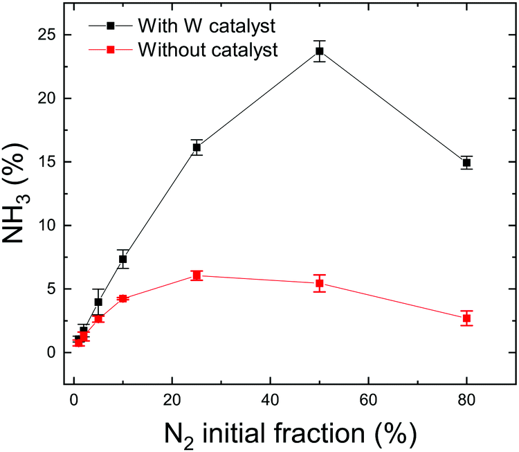 | ||
| Fig. 2 Ammonia production without catalyst (red curve) and with W catalyst (black curve) at RT for different N2 initial fractions. | ||
 | (2) |
The formed ammonia yield is on the other hand defined as the percentage of initial injected nitrogen molecules that converted to ammonia:
 | (3) |
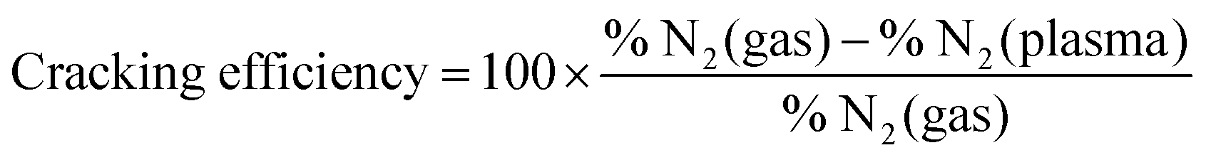
In thermal processes30 and in atmospheric-pressure plasmas,14 the critical elementary step for ammonia formation is the N2 triple bond dissociation as it presents a large free energy of activation (9.8 eV). The role of a catalyst is to decrease this activation energy and support the dissociative adsorption of nitrogen molecules. By comparing the nitrogen cracking efficiency without catalyst and on W surface, the influence of the surface in our low pressure plasma conditions regarding the nitrogen dissociation can be identified.
Both nitrogen cracking efficiency and ammonia formation yield are plotted in Fig. 3 for different nitrogen initial fractions. As can be seen, the trend of the cracking efficiency curve does not change when introducing a W catalyst but the values are slightly increased. This indicates that the W surface either dissociates a part of non-cracked nitrogen from the plasma or the increase is only due to the surface consumption of nitrogen molecules or atoms. In fact, the cracking efficiency is not a direct measurement of dissociated nitrogen molecules but a parameter that presents the missing N2 molecules in the plasma compared to the gas phase including therefore the dissociated molecules, but also adsorbed molecules on the surface. The high cracking efficiencies in plasma only (red curve) suggest then that the plasma dissociated the precursor molecules already before they come into contact with a surface. Hong et al.14 reported that, in low-pressure plasmas (typically operating at pressures in the range from 1 × 10⁻² mbar to several mbar), the dissociation of the gaseous precursors is provided by the energetic plasma environment so that the surfaces surrounding the plasma are bombarded with dissociated species. The direct adsorption of atoms is therefore the dominant process. Particularly, nitrogen molecules are dissociated in the gas phase through the reaction of ionized molecule in the plasma with electrons (e− + N2+ → 2N). The dissociation of the nitrogen triple bond (that requires 9.8 eV of energy) can be also caused by the photons emitted by the excited hydrogen in the plasma and specifically by the Lyman-alpha series lines at 121.6 nm (corresponding to 10.2 eV). Note here that, in thermal ammonia processes, the existence of surface defects is essential for the dissociation of nitrogen (the rate limiting step under these conditions). In particular, the authors in ref. 52 showed that only step sites are active for the N2 dissociation. Based on the results of Fig. 3a), this condition is overcome in the case of plasma assisted ammonia catalysis. However, it would be interesting to study (either experimentally or by DFT calculations) the impact of surface defects on the ammonia formation under plasma assisted catalysis conditions, which lies beyond the scope of this study.
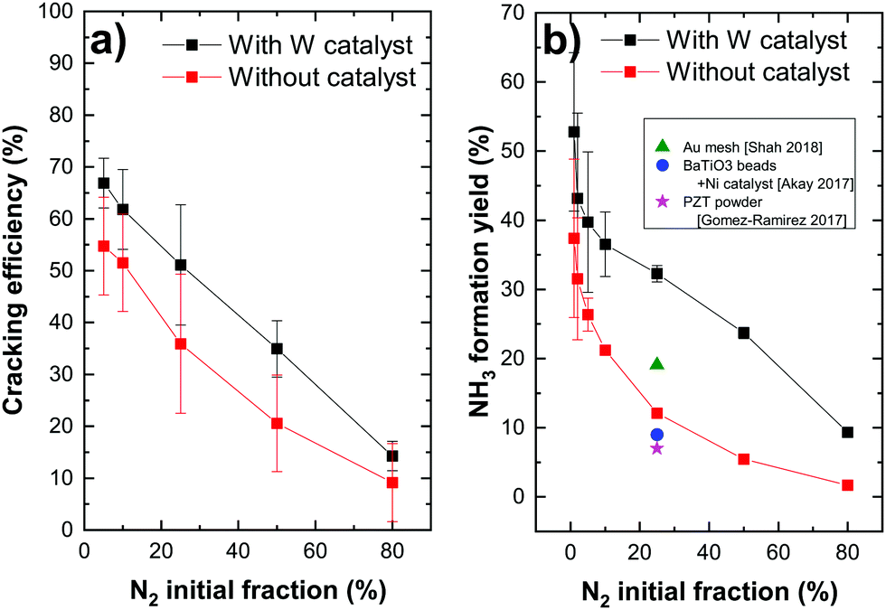 | ||
| Fig. 3 (a) Nitrogen cracking efficiency and (b) ammonia formation yield for different N2 initial fractions (with added data points from previous studies22,30,51). | ||
The decrease of the cracking efficiency with increasing N2 fraction, both with and without catalyst, can be explained by the increase of the recombination rate of cracked nitrogen atoms to form back N2 molecules for a higher nitrogen density in the plasma. Another possible reason of this decrease can be a molecular assisted recombination process of nitrogen molecules in the presence of hydrogen. This process is proposed by Perillo et al.53 through a numerical simulation study of the nitrogen recombination mechanisms in N2/H2 plasma. One of the possible mechanisms they presented (specifically for the plasma edge) has the following reaction paths:
| H2+ + N2 → N2H+ + H |
| e− + N2H+ → N2 + H |
Concerning the formation yield, the catalyst seems to have a great impact on this parameter. The ammonia yield increases from 12% (no catalyst) to 32% (W) and from 5% to 24% for 25 and 50% of N2, respectively. This allowed us to obtain an unprecedented ammonia formation yield, surpassing the yield reported in the literature. In fact, in their recent publications, Hong et al.14 and Shah et al.30 reviewed the literature and provided tables summarizing the ammonia yields for plasma assisted ammonia synthesis in various types of plasma sources operating at atmospheric pressure, such as dielectric barrier discharges (DBDs), pulsed and AC plasmas and at low pressure such as RF plasma discharges. They demonstrated that the ammonia yield of plasma catalytic ammonia synthesis is in the range of 0.1 to 19%. The highest value corresponds to the production of ammonia on a gold mesh catalyst (presented in Fig. 3b) in working conditions of 400 °C of reaction temperature, 0.35 mbar of pressure and 300 W of RF plasma discharge.
In order to compare with the Haber–Bosch process, the energy yield in g-NH3/h was calculated. For 120 W of input power a yield of 0.1 g h−1 was obtained (only the plasma input power was considered here and the power consumed by vacuum pumps and other electronic devices are neglected for simplification reasons). The Haber–Bosch process, on the other hand, consumes an energy value around 12 MW h per ton of ammonia which correspond to 1.2 W of power for 0.1 g h−1, 100 times lower than in our process. Therefore, despite the high ammonia formation yields achieved through RF plasma catalysis in this study, the values for energy yield are still very limited compared to the commercial Haber–Bosch process. With an optimization of the plasma parameters and the catalytic surface, it is expected that substantial improvements of the energy yield will be possible for this process.
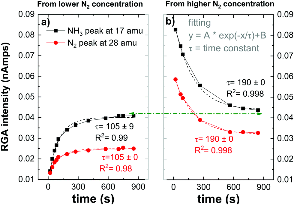 | ||
| Fig. 4 Time evolution of the RGA peak intensities relative to NH3 (at 17 amu) and N2 (at 28 amu) for 5% of N2 initial fraction. | ||
RGA peak intensities reflect an indirect measurement of species on the surface by detecting desorbed species from the surface to the gas phase or missing species from the gas phase which get consumed by the W surface. In Fig. 4, ammonia peak RGA intensities represent the NH3 produced in the plasma volume (or eventually on the quartz tube as discussed in the previous section) and also the ammonia that gets desorbed after being formed on the W surface. However, the nitrogen RGA intensities represent an indirect measurement of the nitrogen consumed or released by the W surface. When comparing both figures (a) and (b) the ammonia peak followed the same trend as the nitrogen peak, saturating both with the same time constant. This observation indicates that the ammonia formation is directly related to the nitrogen adsorbed or released from the surface i.e., NH3 forms through surface nitride steps. This mechanism will be developed in the following section. After reaching the saturation (either by loading the surface with nitrogen or by desorbing residual nitrogen from the preloaded surface), the ammonia peak has a similar value indicating that ammonia formation is not dependent on the initial state of the surface. However, both nitrogen peaks’ saturation values do not overlap. This can be either due to the measurement time that has not been long enough to reach the equilibrium of both signals or to a partial diffusion of the nitrogen inside the W sample that can not be recovered. This was in fact observed by Oberkofler et al.,54 who reported that the main mechanisms for nitrogen retention in N2-seeded discharge of ASDEX Upgrade Tokamak are implantation of nitrogen into plasma-facing materials, co-deposition with other species present in the Tokamak and the formation of ammonia.
3.2 Surface study by XPS in the conventional SS chamber
We will first briefly summarize the dominant reaction pathways for ammonia synthesis on a catalyst surface. In the first Haber–Bosch process developed in 1913 by BASF, ammonia is formed from a reaction between N2 and H2 using an Fe3O4 catalyst. The process takes place at a temperature of around 500 °C and a pressure of 300 bar. The requirement for such high temperature (and as a consequence high pressure to make the equilibrium favor the reaction via the Le Chatelier principle) and catalytic material is justified by the high activation energy of N2 dissociation due to the strength of the triple bond in the nitrogen molecule. The elementary steps of the reactions have been identified by G. Ertl55 and can be written as:
| H2 + * → 2H(s) |
| N2 + * → 2N(s) |
| N(s) + H(s) → NH(s) |
| NH(s) + H(s) → NH2(s) |
| NH2(s) + H(s) → NH3(s) |
In contrast, plasma synthesis provides several different chemical pathways. The two main mechanisms are illustrated in Fig. 5. In the Eley–Rideal (E–R) mechanism, only one of the reactants (either hydrogen (E–R 1) or nitrogen (E–R 2) adsorbs onto the surface, after which the other reactant interacts with the adsorbed species directly from the gas phase, followed by the desorption of the reaction product.
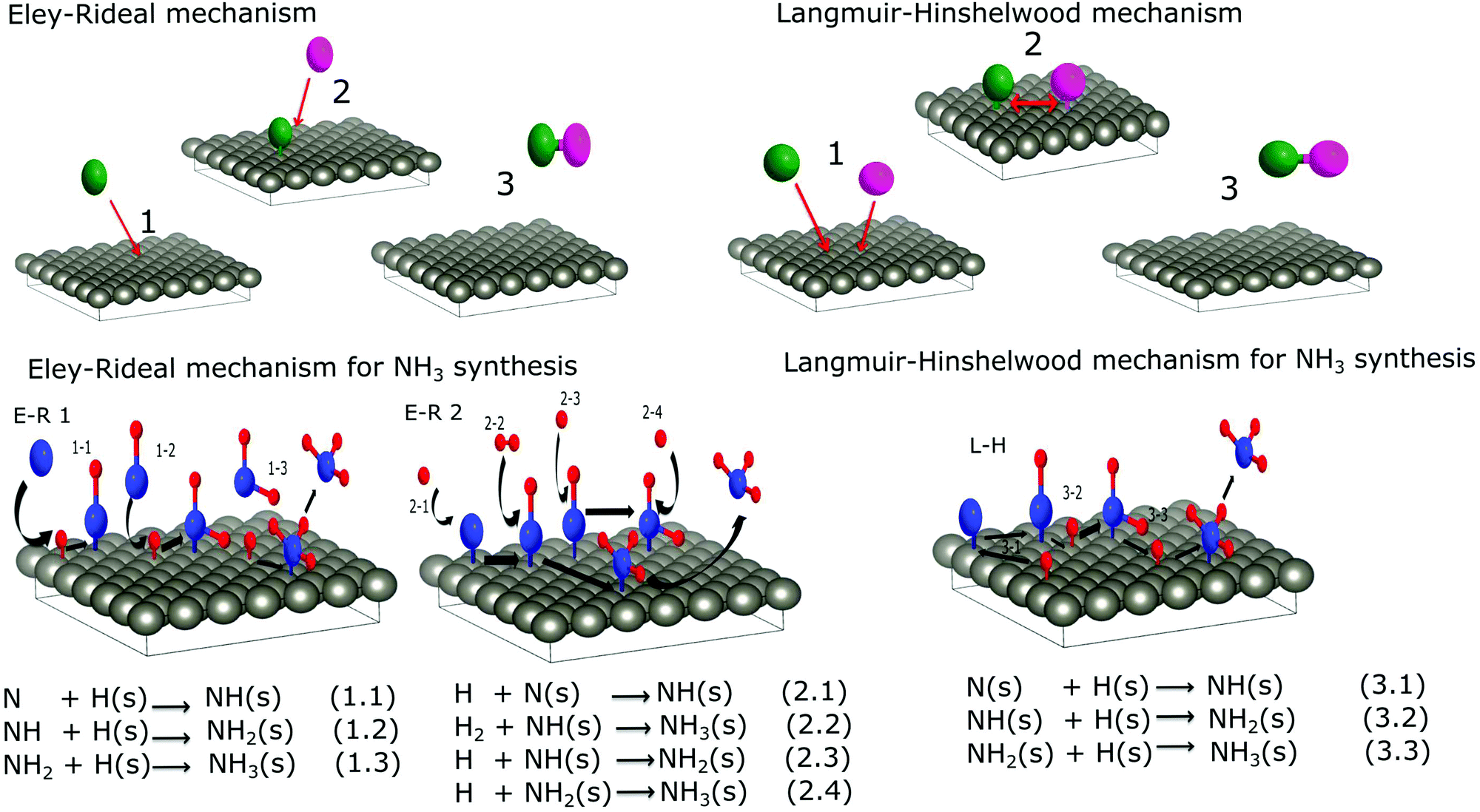 | ||
| Fig. 5 Schematics and equations of ammonia formation surface reactions via E–R interaction (left) and L–H interaction (right). | ||
In the second mechanism called the Langmuir–Hinshelwood (L–H), both reactants first adsorb onto the surface before a reaction takes place. Surface diffusion facilitates interaction between adsorbed molecules and the final reaction product desorbs from the surface. For ammonia synthesis, the L–H mechanism consists of recombination of chemisorbed atomic nitrogen and hydrogen to NH3 at the surface of the catalyst with NH and NH2 as reaction steps. In this type of mechanism, the reactivity is the highest when a stoichiometric amount of reactant is adsorbed on the surface. However, in the E–R mechanism a higher coverage of the adsorbed species, as well as a higher pressure of the other gas, yields a higher reaction rate. Therefore, the maximum production of ammonia at equal nitrogen and hydrogen initial concentrations instead of the stoichiometric mixture shown in Section 2 suggests that the E–R mechanism is more probable than the L–H. Besides the saturation of the ammonia peak that follows the nitrogen evolution shown in the same section is a hint that ammonia formation occurs through nitrogen adsorption on the W surface. Nevertheless, both results from the RGA gas phase study are not sufficient to draw conclusions about the preferential mechanism of ammonia synthesis in plasma catalysis. To get more information about the processes, species that form on the W surface following the plasma exposure were investigated by XPS.
Fig. 6 and 7 represent respectively the W4f and N1s core level spectra measured on the W samples before and after N2 and/or H2 plasma exposures. The W4f core level peaks were deconvoluted into three doublets located at 31.4 eV, 32.4 eV and 33.2 eV assigned to metallic W, WN and WN2, respectively, while the N1s was decomposed into 4 singlets attributed to N, NH, NH2 and NH3. The binding energy (BE) values for both W and N peaks are summarized and compared to the literature values in Table 1.
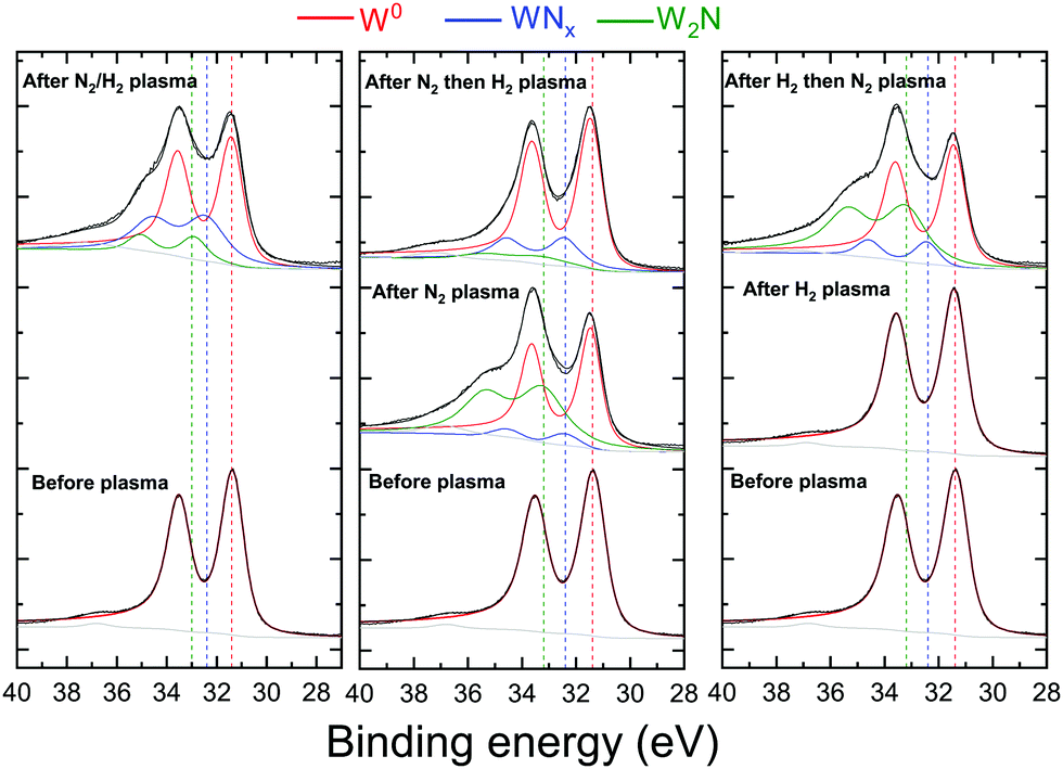 | ||
| Fig. 6 W4f core level spectra recorded before and after N2 and/or H2 plasma exposure of the W surface. The red, green and blue solid curves are the individual chemical states and the dashed vertical lines serve as an eye guide for these states. Solid black curves are the raw data and the sum curves. The graphs were shifted arbitrarily on the vertical axis for ease of viewing. | ||
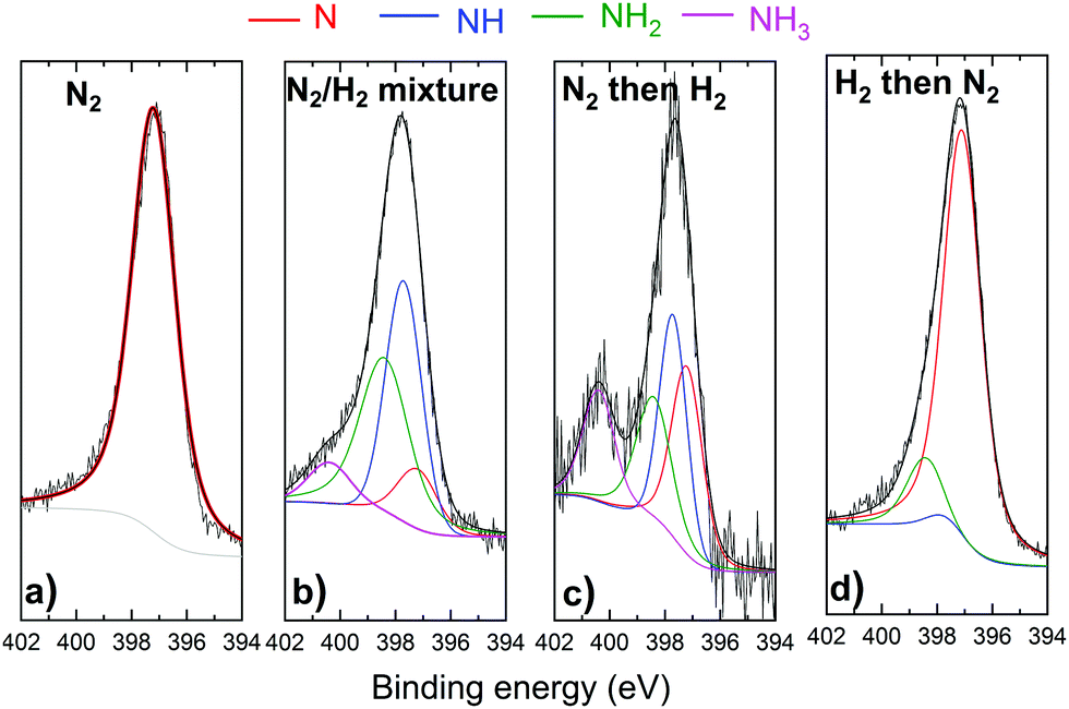 | ||
| Fig. 7 N1s core level spectra recorded before and after (a) N2 (b) N2/H2 (c) N2 then H2 and (d) H2 then N2 plasma exposure of the W surface. The red, green and blue solid curves are the individual chemical states. Solid black curves are the raw data and the sum curves. | ||
W4f core level spectra, in Fig. 6, reveal neither W oxides nor oxynitrides (at 35.8 eV and 33.5 eV38) despite the presence of oxygen on the surface, indicating that the O is only adsorbed on the surface and not bonded to W atoms. When exposed to pure H2 plasma, no changes were observed for the W4f peak from its metallic state. Yet, tungsten nitride peaks are identified for the 4 samples exposed to N2, N2/H2, N2 then H2 and H2 then N2 plasmas. However, some differences can be seen when comparing, for these samples, both tungsten nitride peaks (WN and WN2) representing 2 different stoichiometries. After the exposure of the tungsten to pure N2 plasma or to N2 plasma following the hydrogen pure plasma, WN2 peak intensity (green curve) is higher than the WN peak (blue curve) contrary to the other 2 samples.
For the same 2 samples exposed to N2 only and H2 then N2 plasma, N1s spectra in Fig. 7 present mainly 1 peak identified as a nitrogen peak bonded to W. Very small peaks of NH and NH2 were measured for the H2 then N2 plasma exposed surface. Moreover, no ammonia was detected on this sample. The NH3 was in fact identified for both cases when the surface was exposed to a mixture of N2 and H2 and for N2 then H2 plasma exposure. It should be noted here that the nonformation of ammonia on the sample exposed to hydrogen first then to nitrogen plasma cannot be caused by a thermal desorption of hydrogen. As Ertl addressed in ref. 61, surface-adsorbed hydrogen can be desorbed above 200 °C in vacuo, while under our experimental conditions, the hydrogen nitrogen plasma heats up the W surface from RT by less than 20 °C. However, the low hydrogen retention especially at these low energies can not be excluded as a possible reason for the nonformation of ammonia. It is also interesting to note here that the atomic nitrogen concentrations on the sample exposed to pure nitrogen plasma and on the sample exposed to hydrogen then nitrogen plasma are comparable (34 at% and 36%, respectively). This result suggests that the pre-adsorbed hydrogen does not block the adsorption of nitrogen on the surface.
To summarize, N1s core level spectra show that ammonia can be formed only when the surface is exposed either to a mixture of nitrogen and hydrogen or nitrogen plasma as a first step followed by hydrogen plasma. These results match with those observed by A. de Castro et al.62 who showed that deuterated ammonia was formed as a result of pure deuterium (D2) plasma irradiation on a tungsten sheet previously irradiated with pure N2 plasma. Conversely, the symmetric experiment based on the irradiation of the tungsten wall, previously irradiated with D2 plasma, with N2 plasma did not show significant ammonia production. They suggested therefore that the presence of dissociated nitrogen on the W surface is the first mandatory step necessary to trigger the ammonia formation process.
The results from the RGA study indicate that the maximum production of ammonia on W surface is at equal nitrogen and hydrogen initial concentrations instead of a stoichiometric mixture, suggesting therefore that both species should be maximized in the mixture for an efficient NH3 formation. Besides, ammonia follows the temporal evolution of nitrogen peak saturating both with the same time constant implying indirectly a connection between the ammonia formation process and the quantity of nitrogen that gets consumed by the surface.
On the other hand XPS results show that the ammonia formation is conditioned by the presence of nitrogen on the W surface. In the experiment where the W surface is preloaded with nitrogen and then exposed to hydrogen plasma, ammonia is formed. In contrast, in the opposite experiment the nitrogen is not previously present on the surface, and ammonia is not formed.
On the basis of the above results, the dominant mechanism for ammonia synthesis from N2/H2 plasma can be identified. As explained in the beginning of this section, for the L–H mechanism both nitrogen and hydrogen adsorb and react on the surface implying that the order of the exposure of the surface to pure N2 and H2 would not affect the results in terms of ammonia production on the surface. This was not the case with our measurements, suggesting therefore that the E–R mechanism predominantly contributed to the ammonia formation in the low pressure RF plasma. Besides, the ammonia formation was shown to be conditioned by the presence of nitrogen on the surface (either from the mixture or from the pure N2 plasma) indicating that, in the E–R mechanism, nitrogen gets adsorbed onto the surface and interacts with hydrogen from the gas phase (see E–R 2 in Fig. 5). However, given that XPS measurements are restricted to species identifications on the surface and do not consider what was formed and desorbed as compounds, the conclusions from such analyses should therefore be treated with considerable caution. Complementary in situ measurement in the gas phase of formed and desorbed species are consequently needed to confirm our findings.
In the literature, few researchers have addressed the question of the ammonia formation mechanism from low pressure hydrogen nitrogen plasma. Based on a chemical kinetics model, Shah et al.'s30 calculations reveal that the Langmuir–Hinshelwood mechanism predominantly contributes to the formation of NH2(s) and NH3, while the Eley–Rideal mechanism only contributes 0.3%. On the other hand, Carrasco et al.28 focused on the ion and neutral chemistry in N2/H2 mixtures, with experimental and modelling work in a low-pressure hollow cathode discharge. They showed that both E–R and L–H surface interactions were found to be important in the ammonia production mechanism. Furthermore, a volume-averaged model developed by Body et al.50 demonstrated that the dominant ammonia production mechanism is found to be the Langmuir–Hinshelwood reaction between adsorbed atomic hydrogen and NH2(s) above 25% hydrogen concentration and the Eley–Rideal reaction between free atomic hydrogen and NH2(s) for lower hydrogen proportions.
The NH3 formed in this context is a result of interaction between the plasma and the catalyst. Therefore, both plasma characteristics (density, electronic temperature, excited/ionized species distribution…) and surface properties (nature, active area, roughness, temperature…) would determine the dominant mechanism for ammonia formation. In the review of Hong et al.,14 a simplified model that takes into account two parameters (the gas temperature and surface reactivity) was established to determine the conditions where L–H would be favoured compared to E–R. They stated that, for low-temperature plasma catalysis and low surface reactivity, ammonia formation mainly proceeds by the E–R mechanism. However, as gas and wall temperatures increase, the role of L–H interactions becomes more important. This study was performed for atmospheric pressure plasmas and to our knowledge no general model taking into account both plasma and catalyst properties was set to conclude about the dominant ammonia reaction paths for low pressure plasma conditions. Besides, the disagreement on the dominant reaction pathways in the previous research and also in our study could be the result of the different plasma and catalyst conditions. As an example, most of the previously reported results from the literature considered an iron (Fe) surface as the catalyst and no single modelling study was interested in the catalytic effect of W on the ammonia formation. In this context, to support our experimental findings, the analysis of our measurements by means of a kinetic model which takes into account our experimental conditions (plasma parameters, W surface, pressure, temperature…) is an important task for future research.
4 Conclusions
Low temperature plasma catalysis, particularly radio frequency plasma catalysis, is an attractive option for ammonia formation for an industry adapted process. In this study, we explored the formation of ammonia from an N2/H2 RF plasma both without and with tungsten catalysts for different initial nitrogen fractions. We demonstrated that the presence of the W surface as a catalyst highly increases the formed ammonia percentage by increasing mainly the formation yield and slightly the nitrogen cracking efficiency. Using a combination of low pressure RF plasma and a W surface as a catalyst, unprecedented ammonia yields up to 32% at 25/75% of N2/H2 were obtained, consequently surpassing the yields reported in the literature for different plasma discharges and different catalytic surfaces. So far, it is not clear what is the exact factor that drastically enhanced the formation yield in our experiment compared to previous research. It could be associated with the combination of different experimental conditions: low pressure, low temperature, high dissociation rate in the plasma and enhanced photodissociation of nitrogen by the Lyman lines of dissociated hydrogen. However, it is worth mentioning that the energy yield is still very limited compared to the Haber–Bosch process and needs therefore to be greatly improved. The optimization of the plasma parameters and the catalytic surface could lead to a better formation and energy yield.Furthermore, by means of X ray photo-electron spectroscopy, we could demonstrate experimentally the interaction of species from the plasma with the catalyst surface. By investigating both the tungsten and the nitrogen binding energies to identify the formed species, we proposed a formation pathway of ammonia via the Eley–Rideal mechanism between adsorbed nitrogen and hydrogen from the gas phase.
Conflicts of interest
There are no conflicts to declare.Acknowledgements
This work has been carried out within the framework of the EUROfusion Consortium and has received funding from the Euratom research and training programme 2014–2018 and 2019–2020 under grant agreement no. 633053. The views and opinions expressed herein do not necessarily reflect those of the European Commission or of the ITER Organization. ITER is the Nuclear Facility INB no. 174. This paper applies new physics analysis related to tritiated ammonia formation which is not yet incorporated into the ITER technical baseline. The nuclear operator is not constrained by the results presented here. The authors would like to thank the Swiss Federal Office of Energy, the Swiss Nanoscience Institute, the Swiss National Science Foundation and the Federal Office for Education and Science for their financial support.References
- V. Smil, Nature, 1999, 400, 415 CrossRef CAS.
- R. Lan, J. T. Irvine and S. Tao, Int. J. Hydrogen Energy, 2012, 37, 1482–1494 CrossRef CAS.
- A. Kallenbach, M. Bernert, R. Dux, L. Casali, T. Eich, L. Giannone, A. Herrmann, R. McDermott, A. Mlynek and H. Müller, et al. , Plasma Phys. Controlled Fusion, 2013, 55, 124041 CrossRef.
- M. Oberkofler, D. Douai, S. Brezinsek, J. Coenen, T. Dittmar, A. Drenik, S. Romanelli, E. Joffrin, K. McCormick and M. Brix, et al. , J. Nucl. Mater., 2013, 438, S258–S261 CrossRef CAS.
- D. Neuwirth, V. Rohde, T. Schwarz-Selinger and A. U. Team, Plasma Phys. Controlled Fusion, 2012, 54, 085008 CrossRef.
- V. Rohde and M. Oberkofler, et al. , J. Nucl. Mater., 2015, 463, 672–675 CrossRef CAS.
- Y. Tanabe and Y. Nishibayashi, Coord. Chem. Rev., 2013, 257, 2551–2564 CrossRef CAS.
- K. A. Brown, D. F. Harris, M. B. Wilker, A. Rasmussen, N. Khadka, H. Hamby, S. Keable, G. Dukovic, J. W. Peters and L. C. Seefeldt, et al. , Science, 2016, 352, 448–450 CrossRef CAS.
- R. D. Milton, R. Cai, S. Abdellaoui, D. Leech, A. L. De Lacey, M. Pita and S. D. Minteer, Angew. Chem., Int. Ed., 2017, 56, 2680–2683 CrossRef CAS.
- K. Wang and R. C. Brown, Green Chem., 2013, 15, 675–681 RSC.
- G. Liu, M. Mba Wright, Q. Zhao and R. C. Brown, ACS Sustainable Chem. Eng., 2016, 4, 1819–1826 CrossRef CAS.
- H.-H. Kim, Plasma Processes Polym., 2004, 1, 91–110 CrossRef CAS.
- M. Kitano, Y. Inoue, Y. Yamazaki, F. Hayashi, S. Kanbara, S. Matsuishi, T. Yokoyama, S.-W. Kim, M. Hara and H. Hosono, Nat. Chem., 2012, 4, 934 CrossRef CAS.
- J. Hong, S. Prawer and A. B. Murphy, ACS Sustainable Chem. Eng., 2017, 6, 15–31 CrossRef.
- J. Van Helden, W. Wagemans, G. Yagci, R. Zijlmans, D. Schram, R. Engeln, G. Lombardi, G. Stancu and J. Röpcke, J. Appl. Phys., 2007, 101, 043305 CrossRef.
- P. Vankan, T. Rutten, S. Mazouffre, D. Schram and R. Engeln, Appl. Phys. Lett., 2002, 81, 418–420 CrossRef CAS.
- T. Mizushima, K. Matsumoto, H. Ohkita and N. Kakuta, Plasma Chem. Plasma Process., 2007, 27, 1–11 CrossRef CAS.
- M. Bai, Z. Zhang, M. Bai, X. Bai and H. Gao, Plasma Chem. Plasma Process., 2008, 28, 405–414 CrossRef CAS.
- P. Peng, Y. Li, Y. Cheng, S. Deng, P. Chen and R. Ruan, Plasma Chem. Plasma Process., 2016, 36, 1201–1210 CrossRef CAS.
- J. Hong, M. Aramesh, O. Shimoni, D. H. Seo, S. Yick, A. Greig, C. Charles, S. Prawer and A. B. Murphy, Plasma Chem. Plasma Process., 2016, 36, 917–940 CrossRef CAS.
- A. Gómez-Ramrez, A. M. Montoro-Damas, J. Cotrino, R. M. Lambert and A. R. González-Elipe, Plasma Processes Polym., 2017, 14, 1600081 CrossRef.
- G. Akay and K. Zhang, Ind. Eng. Chem. Res., 2017, 56, 457–468 CrossRef CAS.
- H. Uyama and O. Matsumoto, Plasma Chem. Plasma Process., 1989, 9, 13–24 CrossRef CAS.
- J. Loureiro and A. Ricard, J. Phys. D: Appl. Phys., 1993, 26, 163 CrossRef CAS.
- A. Garscadden and R. Nagpal, Plasma Sources Sci. Technol., 1995, 4, 268 CrossRef CAS.
- J. Jauberteau, I. Jauberteau and J. Aubreton, J. Phys. D: Appl. Phys., 2002, 35, 665 CrossRef CAS.
- S. Touimi, J.-L. Jauberteau, I. Jauberteau and J. Aubreton, J. Phys. D: Appl. Phys., 2010, 43, 205203 CrossRef.
- E. Carrasco, M. Jiménez-Redondo, I. Tanarro and V. J. Herrero, Phys. Chem. Chem. Phys., 2011, 13, 19561–19572 RSC.
- M. Sode, W. Jacob, T. Schwarz-Selinger and H. Kersten, J. Appl. Phys., 2015, 117, 083303 CrossRef.
- J. Shah, W. Wang, A. Bogaerts and M. L. Carreon, ACS Applied Energy, Materials, 2018, 1, 4824–4839 CAS.
- H. Uyama and O. Matsumoto, Proceedings of the Tenth International Symposium on Plasma Chemistry (ISPC-10), Bochum, Germany, 1991, p. 1.
- H. Uyama and O. Matsumoto, Denki Kagaku, 1993, 61, 925–926 CAS.
- S. Tanaka, H. Uyama and O. Matsumoto, Plasma Chem. Plasma Process., 1994, 14, 491–504 CrossRef CAS.
- O. Matsumoto, J. Phys. IV, 1998, 8, Pr7-411 Search PubMed.
- J. Shah, T. Wu, J. Lucero, M. A. Carreon and M. L. Carreon, ACS Sustainable Chem. Eng., 2018, 7, 377–383 CrossRef.
- J. Shah, J. Harrison and M. Carreon, Catalysts, 2018, 8, 437 CrossRef.
- F. F. Chen, Adv. Plasma Technol., 2007, 99–115 CAS.
- M. B. Yaala, L. Marot, R. Steiner, L. Moser, G. De Temmerman, C. Porosnicu, C. Lungu, M. Oberkofler and E. Meyer, Nucl. Fusion, 2018, 58, 106012 CrossRef.
- E. C. Neyts, K. Ostrikov, M. K. Sunkara and A. Bogaerts, Chem. Rev., 2015, 115, 13408–13446 CrossRef CAS.
- S. Iyyakkunnel, L. Marot, B. Eren, R. Steiner, L. Moser, D. Mathys, M. Düggelin, P. Chapon and E. Meyer, ACS Appl. Mater. Interfaces, 2014, 6, 11609–11616 CrossRef CAS.
- M. Wisse, L. Marot, B. Eren, R. Steiner, D. Mathys and E. Meyer, Fusion Eng. Des., 2013, 88, 388–399 CrossRef CAS.
- B. Eren, L. Marot, M. Langer, R. Steiner, M. Wisse, D. Mathys and E. Meyer, Nucl. Fusion, 2011, 51, 103025 CrossRef.
- J. Amorim, G. Baravian and G. Sultan, Appl. Phys. Lett., 1996, 68, 1915–1917 CrossRef CAS.
- H. Uyama and O. Matsumoto, Plasma Chem. Plasma Process., 1989, 9, 421–432 CrossRef CAS.
- J. Hong, S. Pancheshnyi, E. Tam, J. J. Lowke, S. Prawer and A. B. Murphy, J. Phys. D: Appl. Phys., 2017, 50, 154005 CrossRef.
- M. L. Steen, K. R. Kull and E. R. Fisher, J. Appl. Phys., 2002, 92, 55–63 CrossRef CAS.
- P. Mehta, P. Barboun, F. A. Herrera, J. Kim, P. Rumbach, D. B. Go, J. C. Hicks and W. F. Schneider, Nat. Catal., 2018, 1, 269 CrossRef.
- A. Gómez-Ramrez, J. Cotrino, R. Lambert and A. González-Elipe, Plasma Sources Sci. Technol., 2015, 24, 065011 CrossRef.
- H.-H. Kim, Y. Teramoto, A. Ogata, H. Takagi and T. Nanba, Plasma Processes Polym., 2017, 14, 1600157 CrossRef.
- T. Body, S. Cousens, J. Kirby and C. Corr, Plasma Phys. Controlled Fusion, 2018, 60, 075011 CrossRef.
- A. Gómez-Ramrez, A. M. Montoro-Damas, J. Cotrino, R. M. Lambert and A. R. González-Elipe, Plasma Processes Polym., 2017, 14, 1600081 CrossRef.
- K. Honkala, A. Hellman, I. Remediakis, A. Logadottir, A. Carlsson, S. Dahl, C. H. Christensen and J. K. Nørskov, Science, 2005, 307, 555–558 CrossRef CAS.
- R. Perillo, R. Chandra, G. Akkermans, W. Vijvers, W. Graef, I. Classen, J. Van Dijk and M. De Baar, Plasma Phys. Controlled Fusion, 2018, 60, 105004 CrossRef.
- M. Oberkofler, G. Meisl, A. Hakola, A. Drenik, D. Alegre, S. Brezinsek, R. Craven, T. Dittmar, T. Keenan and S. Romanelli, et al. , Phys. Scr., 2016, 2016, 014077 CrossRef.
- G. Ertl, Catalytic ammonia synthesis: fundamentals and practice, 1991, pp. 109–132 Search PubMed.
- O. J. Bchir, K. C. Kim, T. J. Anderson, V. Craciun, B. C. Brooks and L. McElwee-White, J. Electrochem. Soc., 2004, 151, G697–G703 CrossRef CAS.
- D. Wang, J. Chen, H. Zhang and N. Huang, Nucl. Instrum. Methods Phys. Res., Sect. B, 2000, 171, 465–469 CrossRef CAS.
- Y.-W. Yang, J.-B. Wu, J. Wang, Y.-F. Lin and H.-T. Chiu, Surf. Sci., 2006, 600, 743–754 CrossRef CAS.
- H. Zhang, D. Wang and N. Huang, Appl. Surf. Sci., 1999, 150, 34–38 CrossRef CAS.
- C. Egawa, S. Naito and K. Tamaru, Surf. Sci., 1983, 131, 49–60 CrossRef CAS.
- G. Ertl, Catal. Rev.: Sci. Eng., 1980, 21, 201–223 CrossRef CAS.
- A. de Castro and F. Tabarés, Vacuum, 2018, 151, 66–72 CrossRef CAS.
Footnote |
| † Electronic supplementary information (ESI) available. See DOI: 10.1039/c9cp01139k |
| This journal is © the Owner Societies 2019 |