
 Open Access Article
 This Open Access Article is licensed under a
 Creative Commons Attribution 3.0 Unported Licence
Alkaline manganese electrochemistry studied by in situ and operando spectroscopic methods – metal dissolution, oxide formation and oxygen evolution†
Martin
Rabe‡
 a,
Cigdem
Toparli‡§
a,
Ying-Hsuan
Chen
a,
Olga
Kasian
a,
Karl J. J.
Mayrhofer
ab and
Andreas
Erbe
*ac
a,
Cigdem
Toparli‡§
a,
Ying-Hsuan
Chen
a,
Olga
Kasian
a,
Karl J. J.
Mayrhofer
ab and
Andreas
Erbe
*ac
aMax-Planck-Institut für Eisenforschung GmbH, Max-Planck-Str. 1, 40237 Düsseldorf, Germany. E-mail: oer-on-mn@the-passivists.org; Fax: +49 211 6792 218; Tel: +49 211 6792 890
bForschungszentrum Jülich GmbH, Helmholtz Institute Erlangen-Nürnberg for Renewable Energy (IEK-11), Egerlandstr. 3, 91058 Erlangen, Germany
cDepartment of Materials Science and Engineering, NTNU, Norwegian University of Science and Technology, 7491 Trondheim, Norway
First published on 8th April 2019
Abstract
Manganese-based systems are considered as candidate electrocatalysts for the electrochemical oxygen evolution reaction (OER), because of their abundance in biochemical oxygen producing catalyst systems. In this work, the surface of metallic manganese was investigated in situ and operando in potentiodynamic cyclic voltammetry (CV) experiments and potentiostatic chronoamperometry (CA) experiments in NaOH. In both cases, the surfaces were initially reduced. At corresponding potentials, no oxide species can be detected by Raman spectroscopy, though electrochemical data and the absence of dissolution above the reversible potential for reactions of type Mn → MnII indicate that the material is passive. The CV shows anodic peaks at potentials in line with expectations on the basis of thermodynamic data for the oxidation to Mn3O4 and Mn2O3; the thickness of the surface layer increases by a few nm during these peaks, as evidenced by spectroscopic ellipsometry. Dissolution of Mn as evidenced by downstream electrolyte analysis by inductively coupled plasma mass spectrometry in a scanning flow cell (SFC-ICP-MS) of the electrolyte is negligible in the range of electrode potential vs. Ag|AgCl|3 M KCl, EAg|AgCl, up to 0.3 V. Remarkably, Raman spectra already show the occurrence of α-MnO2 at EAg|AgCl > −0.25 V, which is ca. 0.5 V below the potential at which oxidation to MnO2 is expected. This observation is attributed to disproportionation above a certain level of MnIII. For EAg|AgCl > 0.4 V, dissolution sets in, at a constant layer thickness. Above the onset potential of the OER, at EAg|AgCl ≈ 0.6 V, SFC-ICP-MS analysis shows fast dissolution, and the oxide layer thickness is constant or increases. CA experiments during the OER show strong dissolution, and the re-formation of a strongly disordered, β-MnO2-like oxide, which exists in a quasi-stationary state at the interface. Several CV cycles increase the dissolution per cycle and the fraction of α-MnO2 on the surface which cannot be reduced. The high dissolution currents show that metallic Mn is hardly suitable as an OER catalyst, however, at least the MnIV oxides remain stationarily present in the system.
1 Introduction
The high demand for clean, secure and economic energy storage has stimulated great interest in the research for efficient energy conversion and storage devices. Producing H2 through water splitting is one of the most efficient and cleanest ways to meet this demand.1–3 The electrochemical splitting of water involves a hydrogen evolution reaction (HER) at the cathode and an oxygen evolution reaction (OER) at the anode.1–3 While the HER is the desired reaction, the OER as the counter reaction has a large overpotential, due to its complex four electron transfer mechanism. In order to reduce losses during the OER, new catalyst systems are being developed. For knowledge based development, detailed understanding of the involved catalytic processes is essential. Biological oxygen evolution during photosynthesis is achieved in enzymes containing manganese ions in the reaction center,4–7 which has inspired much research on Mn containing heterogeneous and homogeneous catalysts. Accordingly, it is anticipated that manganese oxides are promising materials for catalysts of the oxygen evolution reaction in both natural systems and water electrolysers. A great advantage of manganese is its high abundance on earth, making it available for industrial applications at a low price with low criticality and low vulnerability.8,9A number of studies have been published employing ex situ methods to study manganese oxides MnOx as electrocatalysts, while the number of studies employing in situ techniques is rather limited.10–13 In an ex situ X-ray photo electron spectroscopy (XPS) study, small amounts of MnIV were found after polarisation to potentials at which the OER occurs.10 Increased activity of MnCo2O4 was observed in alkaline electrolyte with the reduction of Mn3.7+ to Mn3.2+ based on ex situ K-edge X-ray absorption spectroscopy (XAS).11 On the other hand, a higher oxidation state of Mn (close to MnIV) was detected with ex situ K-edge XAS in an alkaline environment after the OER.13 Even though in situ and operando are experimentally more challenging than ex situ studies, they can provide detailed insight into the conditions under which electrocatalytic systems work, including the investigation of transient states. Thus in situ studies are essential in order to gain a deep understanding of the catalytic mode of action.14,15In situ X-ray absorption near edge structure (XANES) spectroscopy studies on bifunctional MnOx catalysts showed that mixed MnII,III,III oxide was partially oxidized to a MnIII,IV oxide phase with a structure similar to birnessite under OER conditions.16 Spectroelectrochemical measurements revealed that MnIII becomes unstable in neutral electrolyte during the OER and thus the activity of the catalyst decreases.17 Oxidation of MnO nanoparticles to MnIV under OER conditions in neutral electrolyte was observed by in situ Raman and UV-vis spectroscopy.18 Overall, it emerges from these studies that presence of MnIII in the oxides results in a higher catalytic activity. Furthermore, formation of other metal cations in a high valence state during the OER was observed, e.g. in Co, Mn, Ir and Ni-based systems.19–22
In the cyclic voltammograms (CVs) of metal electrodes, the onset of the OER is indicated by a strong increase in the current. Depending on the system, the high current density can originate from several simultaneous processes in addition to the OER such as transpassive metal dissolution, dissolution of the metal oxide, or rapid pitting corrosion.23 Thus, the ideal in situ method should probe the oxide composition as well as film parameters such as thickness, density or porosity at the same time. In former studies our group successfully employed in situ spectroscopic ellipsometry (SE) to probe metal supported oxide layer thicknesses simultaneously with spectral changes that can be attributed to composition changes in electrochemical setups.24–26 It was shown that passive oxide films forming on Cu dissolve because of single charge oxygen vacancy formation during the OER.25In situ and operando measurements on metallic Cu showed that metastable Cu4O3 forms before the oxide dissolution.24,25 One of the key parameters for the OER is the nature of oxides and their stability during the reaction. Formation of stable oxide films on metallic Mn is possible under neutral and basic aqueous environments. Under such conditions several stable oxides such as MnO, Mn3O4, Mn2O3, and MnO2 in various crystal structures may form.27 Most importantly, the structure and properties of thin oxide films formed in electrochemical processes can significantly deviate from those found in the respective bulk system.24–26,28–30
Different compositions and stability of different manganese oxides with respect to pH and electrode potential can be accessed through the Pourbaix diagram (cf. Fig. S1, ESI†).31 Mn dissolution leads to formation of Mn(OH)2 in alkaline solution, followed by Mn3O4 and Mn2O3 formation upon a potential increase. From the corrosion point of view, manganese oxides are judged as poorly protecting.32 According to the Pourbaix diagram at EAg|AgCl ≈ 0 V Mn2O3 transforms to MnO2 and MnO4− forms in the OER potential region. A detailed understanding of the formation of MnOx during the OER is essential in order to optimize MnOx electrodes for possible applications. It is assumed that MnIII forms during the OER.33 However its existence and why MnIII is stable instead of MnIV under such oxidation conditions are controversial.
Here, we extend the fundamental understanding of MnOx in general and during the OER in particular by investigating the oxide formation on metallic Mn surfaces in alkaline electrolyte at pH ≈ 13. We studied the oxide growth, nature and optical properties of oxides by means of in situ spectroelectrochemical studies during CV and chronoamperometry (CA) potential step experiments. The electrochemistry experiments are coupled with in situ SE as well as in situ Raman spectroscopy. The Mn concentration was analysed downstream by a scanning flow cell-inductively coupled plasma mass spectrometer (SFC-ICP-MS) setup. These techniques allow monitoring of the changes in layer thickness, electronic structure of the oxides on the electrode interface, and monitoring of dissolution in the course of electrochemical reactions.
2 Materials and methods
2.1 Sample preparation
Electron beam evaporated Mn was used as the working electrode. Si(100) single crystal wafers (Siegert Wafer, Aachen, Germany) were used as substrates. Cr and Mn pellets with purity 99.999% (Wieland Edelmetalle, Pforzheim, Germany) were used. Firstly, a 10 nm Cr adhesion layer was deposited on a cleaned Si(100) surface. Subsequently, Mn was evaporated by electron beam evaporation. All evaporation was carried out in a Bestec PVD chamber (BesTec GmbH, Berlin, Germany). During evaporation, the pressure was kept at ≈2 × 10⁻⁶ mbar. Mn was evaporated at an evaporation rate of 1 nm min−1 and a 200 nm thick layer was obtained. Depth profiles of the obtained samples were measured by XPS to ensure the absence of oxidation during evaporation (cf. Section S5, ESI†).2.2 In situ spectroscopic ellipsometry (SE)
Electrochemistry coupled in situ SE experiments were performed using a SE 800 spectroscopic ellipsometer (Sentech Instruments GmbH, Berlin, Germany) working in the wavelength range of 280–810 nm (1.5–4.4 eV). The measurements were carried out during both CV and CA. A Compactstat potentiostat (Ivium Technologies, Eindhoven, The Netherlands) was used to control the electrode potential. A custom build cell was used for in situ SE.28,29 A freshly prepared Mn sample was directly mounted in this cell, which was equipped with liquid flow connections. Cu tape was used to provide an electric contact of the surface of the sample. A Pt counter electrode and Ag|AgCl|3 M KCl microreference electrode (DriRef-2SH, World Precision Instruments, Sarasota, FL, USA) were used. All electrode potentials reported in this work (also resulting from other experimental electrochemical techniques) are referenced against Ag|AgCl|3 M KCl. The electrode potential of the employed microreference electrode has been determined as +0.208 mV vs. standard hydrogen electrode by a calibrated Ag|AgCl|3 M KCl electrode (Metrohm, Filderstadt, Germany). 0.1 M NaOH was used as the electrolyte. During the experiments the electrolyte was externally purged with argon, and flowed through the cell with a rate of 2 mL min−1 using a peristaltic pump (Ismatec IDEX Health and Science, Glattbrugg, Switzerland).During the measurement, the pump rate was reduced to 10.6 μL min−1. Ellipsometric spectra of Ψ and Δ were recorded with a time resolution of ≈55 s. The CV of Mn was conducted with a scan rate of 2 mV s−1 in the potential range of −1.3 V to 0.8 V. Thus, one ellipsometric measurement spans over a range of ≈110 mV. To allow for repetitive cycling, the sweep limits were chosen at the onsets of the HER and OER in order to prevent high currents accompanied by excessive formation of gas bubbles, which obscures spectral measurements. At the solid/liquid interface, reasonable results were obtained in former studies with an interpretation of ellipsometric spectra relative to a reference state, typically an oxide free metal in contact with the electrolyte.
Thus, the first potential scan started at the open circuit potential (OCP) with a cathodic scan until −1.3 V, to reduce the pre-formed oxide on the surface. Similarly, the CA experiments started with a potential step to −1.3 V to clean the surface. The potential and period have been carefully optimised to avoid strong hydrogen evolution and to avoid dissolution. Subsequently, four potential steps were set at 0.1, 0.4, 0.7, and 1.0 V. Each potential step was kept for 5 min.
2.3 Interpretation of ellipsometric spectra
The interpretation of the measured ellipsometric angles Ψ and Δ assumes formation of a thin (thickness d ≪ wavelength of light λ) layer of oxide between the bulk metal and bulk electrolyte. First, the time dependent thickness of the oxide layers was determined using a calibration approach. Δ(λ) spectra in the range 300–800 nm upon increasing d were simulated using a stratified layer model implemented in a home made implementation of a matrix method,34 the function of which has been described elsewhere.35 For each layer, literature values of the complex dielectric functions ε = (n + ik)2, the square of the complex refractive index, were used. The shift of these spectra with respect to a pure metal–electrolyte interface was then calculated.The employed complex dielectric function for NaOH (0.1 M) was based on the Sellmeier dispersion for water at 20 °C by Daimon and Masura,36 and k = 0. To this data, an offset was added that was calculated from a 4th degree polynomial fit of the concentration dependent refractive index of aqueous NaOH solution at 598 nm.37 The dielectric function for Mn was taken from Johnson and Christy.38 For the optical constants of MnOx films, different reported data were compared.39,40 Below 10 nm the calculated film thicknesses δd as a function of the shift in Δ were found to be equal within ±2 nm, as expected for such thin layers.41 The ‘HO MnOx’ dataset from ref. 39 was chosen for calibration for further calculations. The calibration was calculated by a 2nd degree polynomial fit of δd as a function of the shift in δΔ at 700 nm, which was found to be free of major spectral features. The calibration curves and fit result are given in Fig. S2 (ESI†).
For calculation of spectra of the extinction coefficient k of the formed oxide layer a perturbation approach described by Lekner was employed.41 This approach was described in detail in earlier studies of our group.24,25,28,29 Briefly, the measured ellipsometric ratio
| ρ = Ψe−iΔ | (1) |
| ρ = ρ0 + F(ε1,2,θ1,2)J1 | (2) |
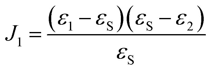 | (3) |
![[Doublestruck R]](https://www.rsc.org/images/entities/char_e175.gif) , εS ≠ 0 were calculated from eqn (3) using the MatLab Symbolic Math Toolbox function solve(⋯). ε2 was calculated from ρ0, assuming an ambient-substrate model. Numerical solutions for the imaginary part of the refractive index k were calculated by
, εS ≠ 0 were calculated from eqn (3) using the MatLab Symbolic Math Toolbox function solve(⋯). ε2 was calculated from ρ0, assuming an ambient-substrate model. Numerical solutions for the imaginary part of the refractive index k were calculated by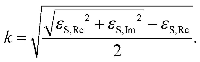 | (4) |
2.4 In situ Raman spectroscopy
In situ Raman spectroscopy measurements were conducted using a Labram confocal Raman microscope (Horiba Jobin Yvon, France). During the in situ experiments an objective with 10× magnification and a numerical aperture of 0.25 was used to illuminate the sample with light from the 514 nm (2.1 eV) line of an Ar ion laser. A Compactstat potentiostat (Ivium Technologies, Eindhoven, The Netherlands) was used for the potential control and current measurements. A custom build Teflon cell was used. Argon saturated NaOH solution (0.1 M) was used as the electrolyte both for CV and CA experiments. The electrolyte was externally purged with argon and it was introduced into the cell using a peristaltic pump (Ismatec IDEX Health and Science, Glattbrugg, Switzerland). A Ag|AgCl|3 M KCl microreference electrode (DriRef-2SH, World Precision Instruments, Sarasota, FL, USA) was used as a reference electrode. A graphite rod was used as a counter electrode.For CA experiments, the potential steps were set at −1.3, 0.1, 0.4, 0.7 and 1.0 V, and were kept for 5 min respectively, the same as the condition in SE experiments. The Raman spectra were recorded with an integration time of ≈32 s. Before applying a controlled electrode potential, three spectra were collected at the OCP. During the potential steps, the spectra were collected from 0.5 min to 4.5 min after applying a certain potential and then averaged. In order to view results from individual spectra in the initial experiments, the whole dataset has been denoised by singular value decomposition (SVD) in GNU Octave. The information from the first 18 components was used to judge trends. Spectra presented in the manuscript are not SVD filtered.
2.5 In situ measurements of Mn dissolution
The SFC-ICP-MS measurements were conducted using the setup described previously.42 Herein an ICP-MS (NexION 300X, PerkinElmer) records dissolution of Mn thin films during the applied electrochemical protocols for CV (2 mV s−1) and CA as described above. As a plasma-based detection method, determination of the valency of the dissolved species is not possible. The evaporated Mn served as a working electrode placed underneath the SFC. The geometric surface area of the electrode corresponds to the opening of the SFC and was 1 × 10⁻² cm2. A graphite rod placed in the inlet channel of the SFC and a Ag|AgClsat. electrode (Metrohm, Germany) were utilized as the counter electrode and the reference electrode, respectively. The measurements were done in argon saturated 0.05 M NaOH solution. A potentiostat (Gamry Reference 600, USA) was used for the electrochemical measurements. Because of technical limitations, high salt contents are unsuitable for measurements with ICP-MS, thus a diluted version of the same electrolyte as for other experiments was used. The potential range was adjusted such that the same potentials vs. reversible hydrogen electrode as in Raman and SE were employed. As an internal standard for detection of 55Mn, 74Ge was used to ensure stable performance of the ICP-MS. The electrolyte flow rate through the SFC was 196 μL min−1. Prior to introduction into the ICP-MS, the electrolyte was mixed with a 10 μg L−1 solution of internal standard in a Y-connector (mixing ratio 1![[thin space (1/6-em)]](https://www.rsc.org/images/entities/char_2009.gif) :1) after the electrochemical cell.
:1) after the electrochemical cell.
In the analyis, it is instructive to compare the dissolved amount with the amount of a single atomic layer per cm2. Considering that the covalent radius of Mn in the lattice is 117 × 10−10 cm and the density of Mn is 7.21 g cm−3, the volume of 1 atomic layer for 1 cm2 of the surface would be 2 × 117 × 10−10 cm. Taking into account that 7.21 g of Mn corresponds to a volume of 1 cm−3, the mass of 1 atomic layer for 1 cm2 is 2 × 117 × 10−10 cm3 × 7.21 g × 1 cm−3, which equals 168.7 × 10⁻⁹ g.
3 Results
The raw data, calibration data and models for all methods are available in a data package associated with this work.43 All electrode potentials in the following sections and figures are reported referenced to Ag|AgCl|3 M KCl, if not explicitly stated otherwise.3.1 Electrochemistry of Mn in alkaline electrolyte
Fig. 1 shows a typical CV of a Mn working electrode in NaOH (0.1 M), as measured in the in situ SE setup. In these experiments, currents during the OER and HER were kept low to avoid formation of disruptive gas bubbles during the long lasting in situ spectroscopy experiments. The first anodic scan of a CV showing the typical high currents below the HER onset at −1.2 V and above the OER onset at ≈0.55 V is shown in Fig. S3 (ESI†).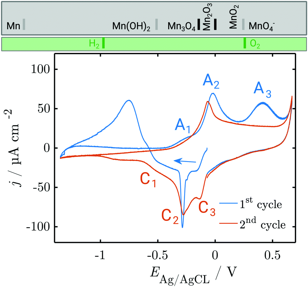 | ||
| Fig. 1 CV of metallic Mn in 0.1 M NaOH, deoxygenated by Ar purging. The first and second cycle are shown; subsequent cycles resemble the second cycle. Scan rate = 2 mV s−1. At the top, the thermodynamic stability ranges of different manganese oxides (grey box) and water species (green box) are shown. Grey separation lines depend on the activity of dissolved Mn, while black separation lines do not. See the ESI† for detailed thermodynamic diagrams. | ||
The CV experiments started with a cathodic scan to obtain a reference state in which the surface contains a minimum amount of oxide, as is used in interpretation of SE data below. A sharp cathodic peak at −0.3 V indicates the reduction of preformed oxide. A broad anodic peak at ≈−0.75 V follows, unusual in a cathodic scan, but observed previously in comparable systems.31
In the first positive scan, the current is initially low, before three major peaks are observed, labelled A1, A2 and A3 (see Section 4). The second as well as the subsequent cycles differ from the first. In the cathodic sweep, three major cathodic peaks are observed (C1–C3) indicating the stepwise reversible reduction of the oxide layer. The anodic peak is not reproduced in the subsequent cathodic sweeps. In the second anodic sweep, only one major peak is observed at ca. −0.05 V. The differences between the first and the subsequent cycles show that the initial interface was changed irreversibly during the first cycle. The anodic peak A3 does not reappear in the subsequent cycles. However, the current density remains increased and a possible oxidation peak might be covered.
In order to resolve the dissolution of Mn, SFC-ICP-MS experiments were carried out. No Mn dissolution was observed during an initial reduction for 2 min at −1.2 V. The dissolution profile measured online during the CV is shown in Fig. 2a and b. The close up view of the first cycle reveals that three major dissolution features are observed during the first cycle (Fig. 2c and d).
 | ||
| Fig. 2 Dissolution profiles of a Mn electrode in alkaline solution: (a and c) applied potentials and (b and d) dissolution profiles measured in situ during the three CV experiments in the range between −1.2 and 0.8 V with a scan rate of 2 mV s−1. (c and d) Close up view of the Mn dissolution rate measured during the first CV. Dissolution of one atomic Mn layer corresponds to 169 ng cm−2. | ||
The first dissolution peak observed during the anodic scan with the onset at ≈−0.3 V corresponds to the peak A1 in Fig. 1 with the same onset potential. A quantification shows that ≈3 ng cm−2 was dissolved from the surface. A further increase of the potential up to 0.3 V results in decreased dissolution. At 0.3 V the dissolution starts rapidly increasing. The onset of dissolution coincides with the A3 peak (Fig. 1). This peak results in a loss of 233 ng cm−2 of Mn from the surface, making it the dominant contribution to the dissolution of Mn under the applied electrochemical procedure.
During the cathodic potential sweep, only insignificant amounts of Mn dissolve as soon as the potential approaches 0.01 V, coinciding with C3 (Fig. 1). Overall, ≈239.1 ng cm−2 of Mn was dissolved during the first cycle. With each new cycle, dissolution decreases. During the second cycle, ≈234 ng cm−2 was removed, while the third cycle led to dissolution of 210 ng cm−2. For comparison, the dissolution of one atomic layer corresponds to a loss of 169 ng cm−2 (see Section 2.5).
3.2 Structural investigations of the oxides formed during CV
To elucidate structural details of the transformations encountered, in situ Raman measurements were conducted during CV. The overall spectrum is dominated by the Raman modes of NaOH. Significant potential-dependent spectral features of interest were observed in the region 300–800 cm−1 (Fig. 3). The overview shows that during the three performed cycles, peaks evolve and diminish upon oxidation and reduction.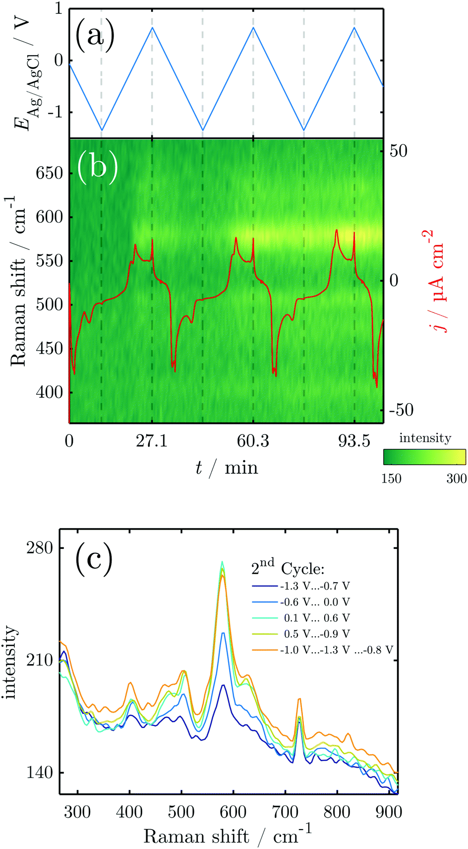 | ||
| Fig. 3 Results of in situ Raman spectroscopy during CV: (a) sweep potential; (b) overview of the Raman spectra and current density obtained during several CV cycles. (c) Raman spectra averaged over the region indicated in the graph. | ||
In the initial Raman measurements at the OCP, two peaks start to emerge at 590, 630 and 725 cm−1. The two peaks at 590 and 630 cm−1 grow in intensity at the OCP, and disappear at the beginning of the reduction process, while the latter is almost unaffected by the ongoing reduction process. During the initial cathodic scan, and in the first anodic scan until the potential increases above ≈−0.25 V, the only peak visible in the oxide region is the one at 725 cm−1. The potential at which the peaks at 590 and 630 cm−1 start to reappear coincides with the later stages of the A1 and the early stages of the A2 peak in the CV.
From the second scan onward, throughout the studied potential range, and also throughout the remaining scans, peaks are observed at ≈405, 470, 505, 590, 630 and 725 cm−1, with the peak at 590 cm−1 and its shoulder at 630 cm−1 dominating at least at the high potentials.
Fig. 4 shows the results of a SE measurement during 4 consecutive voltammetric sweeps. The thickness of the oxide layer was calculated from ellipsometric data as described in Section 2.3. The oxide layer thickness δd increases in parallel to the rising of the anodic peaks in the current density and decreases simultaneously with the cathodic peaks. The increase and following decrease in δd become larger with each cycle, being a maxium of ≈6 nm in the first and 13 nm in the fourth cycle. Generally, most of the oxide produced during the anodic sweep is reduced during the cathodic sweep. Furthermore, a continuous increase of δd with time is found spanning all 4 measured cycles. This observation might be an artefact due to increasing roughening of the surface during cycling or similar effects not regarded in the data analysis.
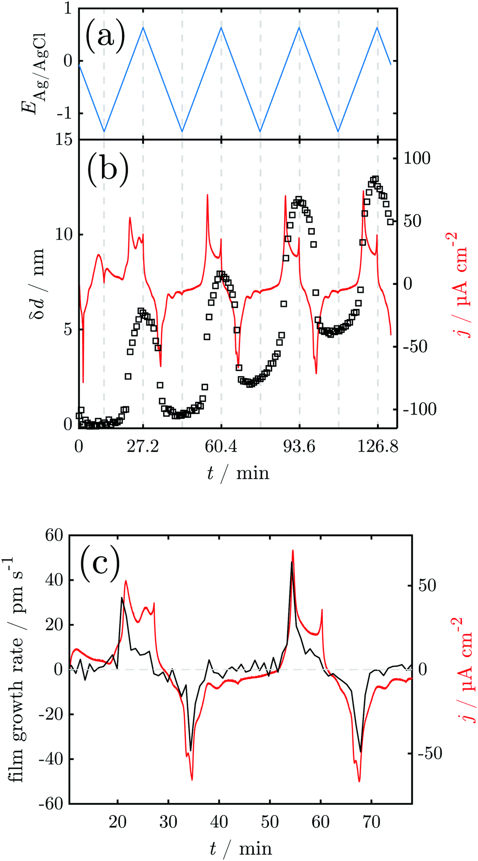 | ||
Fig. 4 Results of in situ SE during CV: (a) sweep potential; (b) change of the oxide layer thickness and current density. (c) Oxide layer growth rate and current density for the first full cycle against time. The horizontal line indicates  . . | ||
For a detailed analysis of the oxide layer formation and stability, the differential film growth rate δ(δd)/δt was calculated by numerical differentiation of the thickness and is plotted together with the current density in Fig. 4c for the first and second cycle. At the anodic peak A2 at ca. 0.1 V, strong growth is observed, followed by a period of more moderate growth, and the A3 region with moderate current density in the potential region 0.2–0.5 V. Remarkably, at the onset of the OER above 0.55 V, which is indicated by the increase of the current density after ≈27 min and ≈60 min, the growth rate drops to zero. In the following cathodic sweeps, the growth rate becomes negative, i.e. the layer shrinks, under the cathodic peaks, indicating the reduction of the oxide layer.
The k spectra of the growing oxide layer during all CV cycles are shown in Fig. 5. Generally, spectra can only be considered meaningful in the regions where a measurable oxide film thickness is present, i.e. after the onset of the anodic peaks and before the tail off of the cathodic peaks. In these regions the spectra show broad peaks that are centered in the region 2.5–3.0 eV (Fig. 5). The peaks change in a repeatable pattern that is reproducible upon subsequent cycles as shown for the 3rd cycle in Fig. 5c. At the onset of the anodic oxide film growth at 0 V, the peak is centered around 2.9 eV and has significant intensity around 3.5 eV. With increasing potential, it shifts continuously to reach ca. 2.7 eV at the onset of the OER at 0.64 V. At the same time, the peak becomes narrower, losing significant intensity at the high energy side around 3.5 eV. Upon the subsequent decrease of the potential, the peak maximum shifts back to 2.9 eV and broadens significantly on the high energy side of the peak.
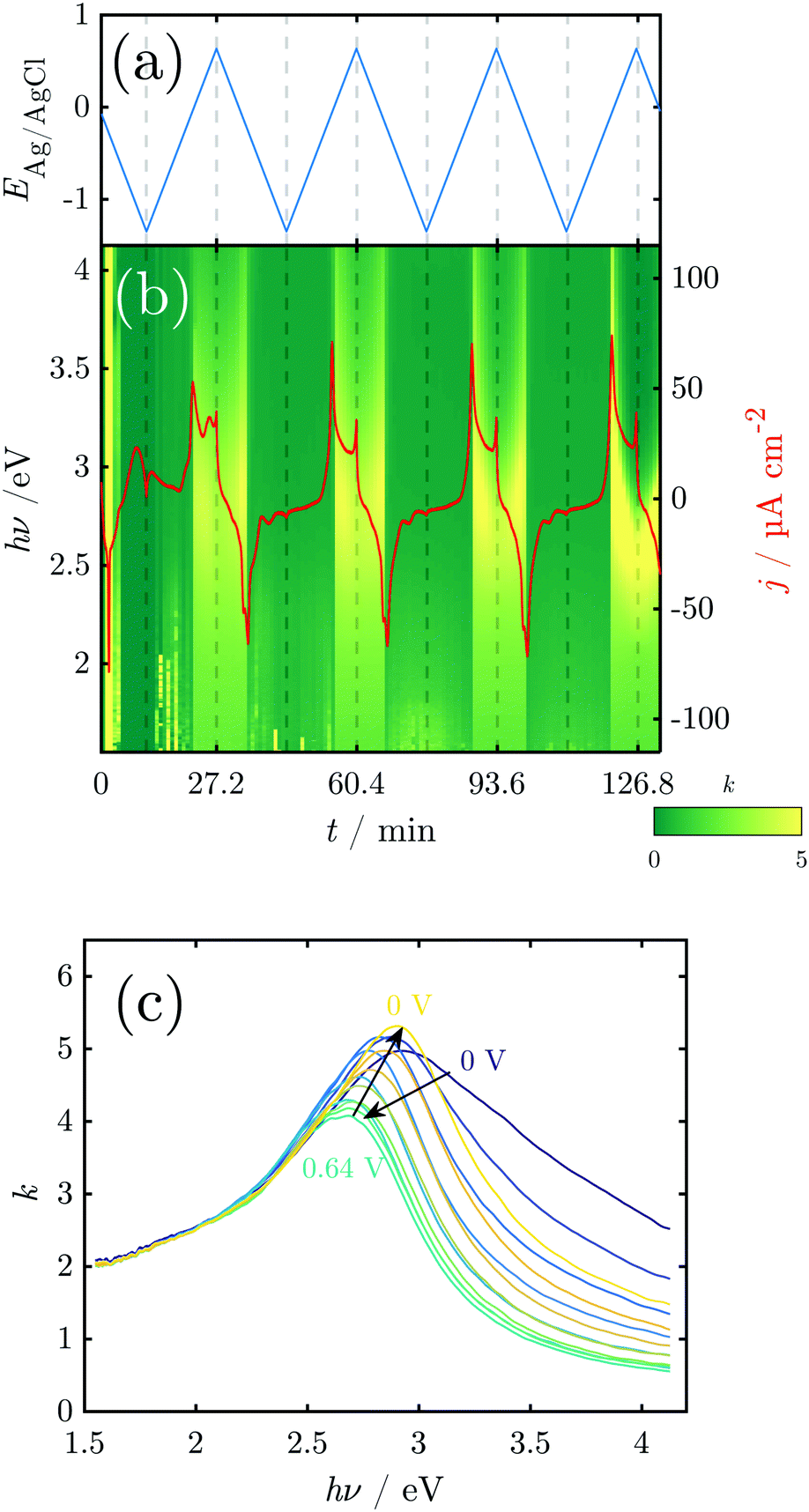 | ||
| Fig. 5 Results of in situ SE during CV: (a) sweep potential; (b) k-spectra and current density. (c) k-Spectra above 0 V during the 3rd cycle illustrate a reversible red shift of the peak maximum between 0.0 and 0.5 V. | ||
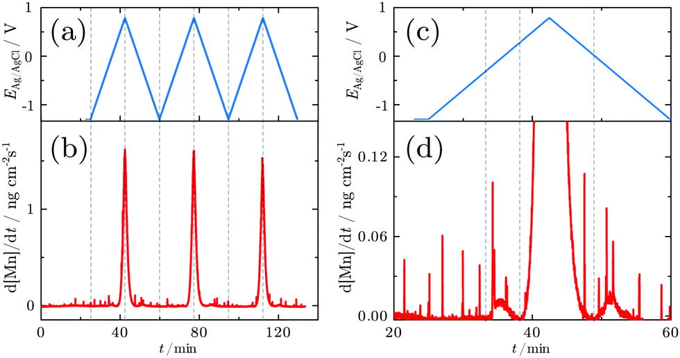
3.3 In situ investigations during CA experiments
In order to probe differences between potential-dependent features as observed in CV experiments and time-dependent features, such as e.g. nucleation triggered processes, Mn electrodes were investigated under potentiostatic conditions in CA experiments. Fig. 6 shows the applied potential program (a) and corresponding dissolution rate (b) as a function of time. The potentiostatic steps were chosen in the oxidative regime to cover the potential region just above the oxidation peaks A2 (0.1 V) and A3 (0.4 V) and the OER region at low current (0.7 V) and higher current (1.0 V). No dissolution is observed when the electrode is polarised at 0.1 V, while 2.3 ng cm−2 and 123.7 ng cm−2 of Mn dissolve during the 5 min of polarisation at 0.4 V and 0.7 V, respectively. The amount of dissolved Mn is significantly increasing when the electrode is polarised at 1 V, where the OER takes place. The dissolution profile has two regions with different slopes. The dissolution rate at 1 V Mn is enormously high, and thus far beyond the linearity region of the calibration curve of the ICP-MS. Consequently, dissolution in this regime cannot be quantified reliably.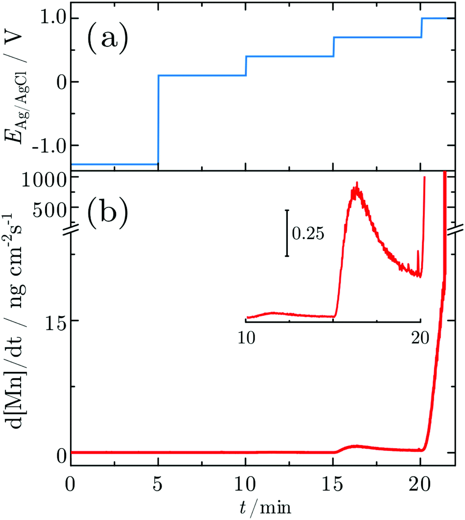 | ||
| Fig. 6 Dissolution profile of a Mn electrode during CA. (a) Applied potentials and (b) the dissolution profiles measured in situ. The inset shows an enlarged view of the dissolution profile during stepping the potential from 0.4 V to 0.7 V. Dissolution of one atomic Mn layer corresponds to 169 ng cm−2. | ||
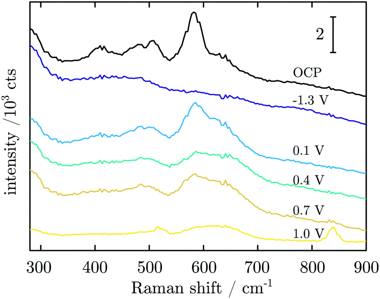
Fig. 7 shows Raman spectra measured during CA experiments. At the OCP, a native Mn oxide with peaks at ≈406, 482, 505 and 582 cm−1 is observed. When applying a reducing potential at −1.3 V for 5 min, all peaks vanish. With the first oxidation step at 0.1 V, peaks at 482, 505, 586 and 626 cm−1 are observed. When the potential is stepped to 0.4 V, the intensity of all peaks decreases, though a small increase in thickness is detected. At 0.7 V, no obvious change is observed. After a further potential step to 1.0 V, two sharp peaks at 516 and 839 cm−1 with a broad peak at ≈620 cm−1 are detected.
 | ||
| Fig. 7 Averaged in situ Raman spectra obtained in CA experiments at the potentials as indicated in the figure. | ||
Fig. 8a shows the current density and oxide thickness during a CA experiment. The initial 3 spectra were recorded at the OCP before the application of potential control. A 2 nm thick native oxide was reduced at −1.3 V. The layer thickness increases rapidly when stepping the potential to 0.1 V and remains then at ≈4–5 nm. When the potential steps to 0.4 V, the layer thickness quickly increases slightly to 5–6 nm. The layer thickness does not change significantly at 0.7 V (Fig. 8), indicating a constant layer thickness at the beginning of the OER regime. However, with a further potential step to 1.0 V, the thickness initially remains constant but then starts to linearly increase with time. At the same time, the relatively high constant current density indicates oxygen formation. It should be noted that the film growth does not slow down or stop within the 5 min the potential is held at 1.0 V. The final range of constant thickness starting after ≈27 min in Fig. 8 is when the potential control is turned off, i.e. when the potential relaxes back to the OCP. Thus, the film formed during the OER remains stable on the interface.
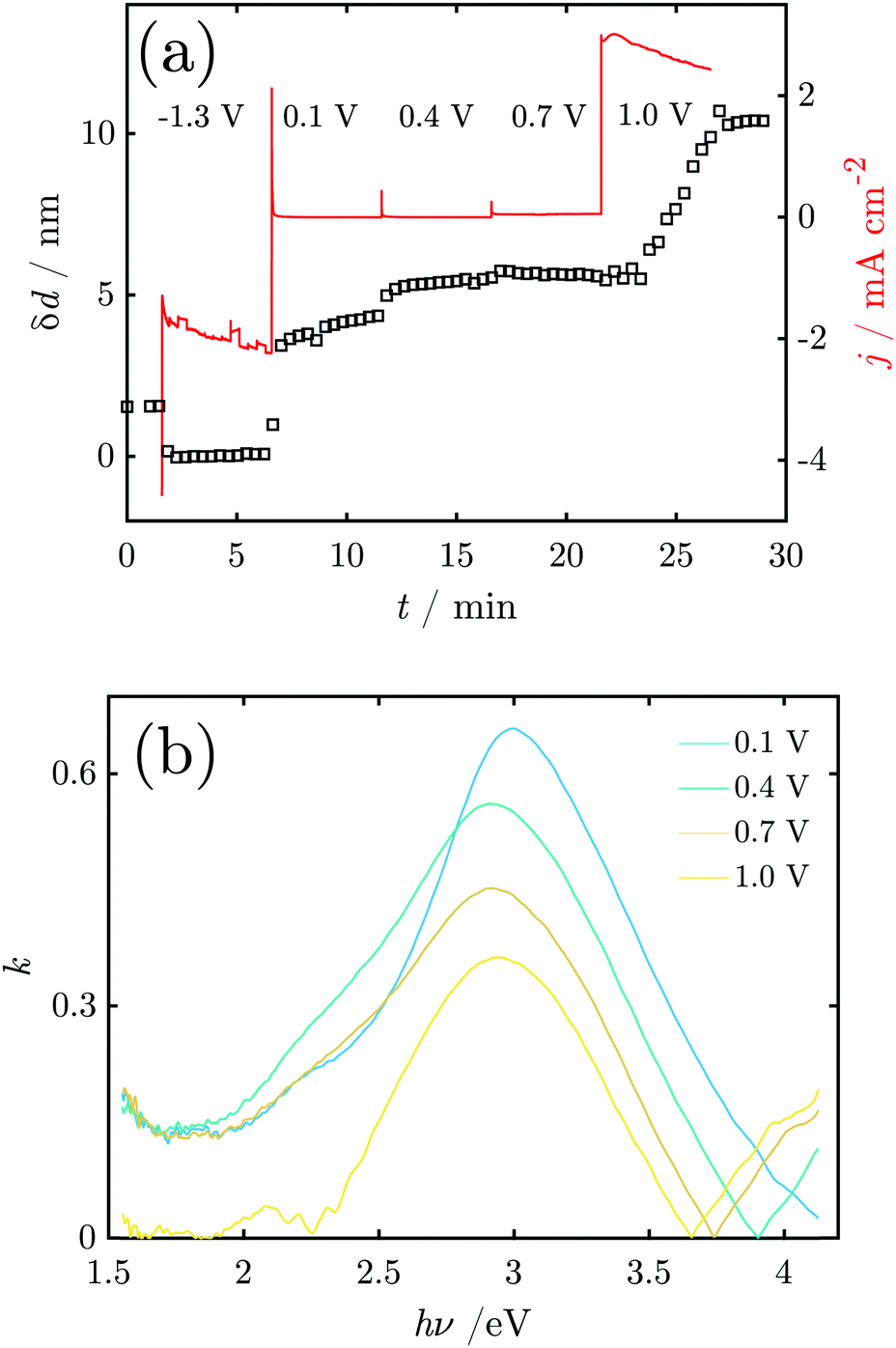 | ||
| Fig. 8 (a) Current densities and thickness of the growing oxide layer as a function of applied potential. The applied electrode potentials are indicated in the curve. (b) Examples of the imaginary part k of the refractive index of the oxide layer on Mn obtained in situ during CA experiments. | ||
Fig. 8b shows the k-spectrum of the oxide layer at different electrode potentials. The initial peak maximum at E = 0.1 V is found at 3.0 eV, which shifts to 2.9 eV at higher potentials. Furthermore, the peaks become broader at the low energy side around 2.5–2.7 eV, indicating a shoulder in that region.
4 Discussion
4.1 Assignment of the Raman spectra
First, it is attempted to assign the peaks observed in the Raman spectra during CV; the features in the spectrum at the highest CA potential shall be discussed in Section 4.3. A table with an overview of the observed peaks and possible assignments to certain modes of certain species is given in Table S2 (ESI†). α-MnO2 (hollandite) is known to show vibrational modes close to all the peak wavenumbers observed during CV experiments reported here, except 725 cm−1.44,45 The peaks at 590 and 630 cm−1 dominate the spectra. The mode at ≈470 cm−1 is usually not Raman active in α-MnO2,45 however, defects may lead to a local symmetry break and a consequent change in the selection rules. Based on a comparison with spectra from many different manganese oxide phases (cf. Table S2, ESI†),45 we conclude here that α-MnO2 is present and dominating the spectra. From all phases analysed in ref. 45 a peak at ≈725 cm−1 is present in the MnO2 modifications romanechite and nsutite. However, this peak was here already present in the initial stages of the experiment, not observed in the CA experiments and does not follow a strong potential dependence, and may as well be related to a different species. It shall hence not be used for further analysis.While some of the observed peaks would also correspond to vibrational modes in other manganese oxides, other characteristic, strong peaks from these are absent in the spectra recorded here.45 For instance, Mn3O4 should show a dominant mode at 650 cm−1 absent here and α-Mn2O3 should show peaks at 314 and 700 cm−1 which are absent here. γ-Mn2O3 should show a mode at 310 cm−1 which is absent and has no peak at around 580–600 cm−1 where the species have their dominant mode. Also the reference spectra of MnO and MnOOH have little resemblance with those observed here.45 It must be pointed out, though, that the absence of dominant signatures in the Raman spectra does not exclude the presence of these species on the surface; indeed, α-MnO2 may only be the dominant species because of its large Raman intensity.
Strikingly, all mentioned peaks except the one at 725 cm−1 appear coincidentally and increase and decrease more or less evenly throughout the experiment. This means that no major changes in the relative composition of the oxide film are probed with Raman spectroscopy. As expected, the peak intensities increase during the anodic scan while they decrease during the cathodic sweep. However, the peaks do not vanish completely after the reduction peak, which is particularly obvious in the later cycles (Fig. 3c). The remaining intensity after reduction increases with every cycle (Fig. 3b), showing the existence of remaining oxide that cannot be reduced.
4.2 Oxides and dissolution during CV
Starting from the OCP, we shall discuss the fate of the surface during a CV experiment, in the sequence of the experiments conducted here.The nature of the broad anodic peak in the initial negative scan at ≈−0.75 V was previously not understood31 and as no Raman peaks were observed associated with this peak, no assignment is possible in this work. However, anodic peaks in negative scans are the sign of a feedback step in the reaction mechanism.46 The disproportionation of MnIII may play a role in such a mechanism.47 Also in the positive scan a decrease in current is observed with increasing potential, nevertheless this interesting feature is only characteristic of the first scan, and shall therefore not be investigated further in this work.
For a metal which is as active as Mn, the Pourbaix diagrams show that full reduction of the oxide is thermodynamically only possible outside the stability range of water.31,48,49 Consequently, a surface oxide can thermodynamically form also at negative electrode potentials. With a reversible potential for the oxidation of Mn to MnII below the lower limit of the scan's potential window, and the absence of Mn dissolution below −0.3 V, we reason that some passivating surface species must be present in the system, for which Mn(OH)2 is a candidate (cf. Fig. S1, ESI†). The oxide amount is below the sensitivity of the Raman experiment; the ellipsometric thickness measurements thus are in relation to a surface covered with this type of oxide. The absence of peaks in Raman in this potential range justifies this procedure. As Mn(OH)2 is dominant only at dissolved Mn activities >10−6 (Fig. S1a, ESI†), the activity of dissolved Mn must be on this order of magnitude, determined by the solubility of the surface oxide.
The peak A1 was assigned earlier to Mn3O4 formation,31 which is in line with thermodynamic expectations (Fig. 1 and Fig. S1, ESI†). During formation of this oxide, only submonolayer fractions of Mn dissolve, and a layer with a ≈4 nm thickness of Mn3O4 forms, effectively hindering dissolution. The layer growth rate (Fig. 4c) shows that the current in this region is predominantly leading to layer growth.
A2 was attributed to the formation of Mn2O3, also in line with thermodynamic expectations.31 Low dissolution shows that this oxide is also protecting the surface; the observed layer thickness grows by ≈2 nm. However, Raman spectra show that during this peak, MnIV is already present. Beam damage has been investigated and discussed previously44 and, based on experience with other systems sensitive to beam damage,50 we do not consider it likely to occur under the conditions of this work.
A3 was earlier attributed to the formation of MnO2.31 Strong dissolution was observed during and after A3, while the layer thickness did not grow significantly during this peak (Fig. 4). Thermodynamically, MnO2 formation may also begin under the peak A2, with A3 indicating permanganate formation. The dissolution current during the peak is, however, still on the order of a few atomic layers of Mn (Fig. 2) so that some level of passivity is maintained during A3.
Remarkably, MnO2 is observed in the Raman spectrum already in the region of the overlapping peaks A1/A2, i.e. well below its reversible potential. As the onset of the observation of MnO2 is not clearly related to one peak, we reason here that above a certain critical concentration of MnIII, disproportionation sets in, 2MnIII → MnII + MnIV.47,51 As a small amount of dissolution was observed before MnO2 formation, dissolved MnIII may or may not play a role here.
A sharp increase in current density at 0.55 V indicates the onset of the OER. Thus, the OER in this system begins with an overpotential of 0.3 V above the value thermodynamically expected at this pH (cf.Fig. 1 and Pourbaix diagram in Fig. S1, ESI†). When the OER starts the oxide layer does not grow further, but it also does not shrink. On the other hand, strong dissolution currents are observed, implying that a layer with constant thickness exists, in which dissolution and re-formation lead to a stationary thickness.
During the negative scans, the thickness of the layer decreases at insignificant dissolution. Dissolution is only observed during peak C3, implying that the reduction of the oxides of oxidation number <IV happens in the solid.
Cycling stabilises the Mn surface, and decreases the amount of dissolved Mn per cycle (Fig. 2), in agreement with the Raman data presented in Fig. 3b, indicating formation of an MnO2-fraction that cannot be reduced in the window of potentials chosen for the experiments. Complementary, the in situ SE measurements presented in Fig. 4 confirm an increase in the thickness of the oxide layer with each new cycle; the fraction of thickness that cannot be reduced must be related to the presence of MnO2 and prevent dissolution of some fraction of metallic Mn. While such oxide formation is not observed in the early stages of the experiments, the continuous cycling obviously modifies the surface such that a complete reduction of oxide is not possible any more in later stages of the experiment. We do not consider dissolution and redeposition of Mn as very likely here, as (i) the chosen potential is above the deposition potential of Mn and (ii) deposition of metallic Mn would significantly decrease the intensity of the MnO2 peaks in the Raman spectrum, due to its intransparency. Rather, we argue here that the fact that the oxide cannot be completely reduced is responsible for the differences between the different CV cycles. While ex situ XPS measurements show that we start with an MnII oxide, this oxide is not recovered after once generating MnO2 at the surface, thus the A1 peak disappears.
The Raman results show that the formation of MnO2 begins already at the first anodic peak, i.e. at lower potentials than suggested previously.31 The peaks associated with MnO2 remain present up to the OER onset and the Raman spectra show no evidence of formation of other oxide species. It should, however, be noted that this does not exclude the possibility of the existence of other oxides.
The observed k-spectra may indicate the presence of different oxide species. The allowed direct band gap of electrodeposited MnO2 was found to be 2.7 eV, while the allowed indirect band gap was measured as 2.1 eV through UV-vis spectroscopy.52,53 Thus the peak at ≈2.7 eV found here at the onset of the OER may indicate the direct band to band transition of MnO2.52,53 However, for a defect-free semiconductor, the bandgap marks the lowest photon energy of photon absorption, not a peak. Consequently, significant defect concentrations must be present in the oxide to modify the absorption spectrum, or at least part of the oxide must have a significantly lower band gap than 2.7 eV. It is worth noting the absence of photoluminescence from the Raman spectra; consequently no direct bandgap can exist in the system of <2.33 eV. An in situ UV-vis study on a manganese oxide electrocatalyst in neutral electrolyte showed an absorption peak shifting from 470 nm to 510 nm (≈2.65 eV to ≈2.4 eV) by increasing the electrode potential to the OER region.17 Other studies suggested the formation of MnIII and also a birnessite type structure during the OER.16,54 The direct band gap of a cation free birnessite structure was calculated as about 3.0 eV, and the indirect band gap as ≈2.6 eV.55 Thus, the shift in the peak during the OER observed here may be associated with the formation of a reduced birnessite-type structure. At the same time, MnO2 must still be present at the surface during the OER, as evidenced by Raman spectroscopy.
After the experiments, XPS results indicate the presence of Mn3O4 on the surface (Section S5, ESI†). It is thus likely that outside an aqueous environment, the surface is partially reduced.
4.3 Oxides and dissolution during CA
Raman spectra at the OCP show the peaks assigned above to α-MnO2 (hollandite) vibrational modes.44,45 Compared to the result during CV, the peaks are broader, indicating that the native oxide is more strongly disordered, and may also include different kinds of Mn oxides with α-MnO2 as the dominant phase. In addition, the peak at 725 cm−1 not related to α-MnO2 and the Raman inactive peak at 470 cm−1,45 which are observed during CV, are not observed in CA experiments. It is possible that the latter peak is related to the transition product during oxide formation. The native oxide is again reduced to the maximum possible extent, shown by the thickness decrease measured by SE and the absence of peaks in the Raman spectrum.From −1.3 V, the potential was stepped to 0.1 V, a potential above peak A2 from the CV, and no dissolved Mn was detected at this potential. The Raman peaks of α-MnO2 were observed again, and no peaks indicating other oxides.44,45 The surface layer thickness jumped to >4 nm with the potential jump, and continued to grow; the anodic current consequently mainly leads to oxide grow rather than dissolution at this potential.
The second potential jump to 0.4 V leads to a potential just above the maximum of CV peak A3. Only negligible dissolution is observed by ICP-MS, and the current is stable. The additional oxide growth is below 1 nm. Remarkably, the Raman peak intensity decreases throughout the spectrum. This decrease cannot be related to oxide dissolution, and must be related to a transition of the oxide into a form which is less Raman active. The third potential jump to 0.7 V goes just above the OER onset and no change in thickness or in Raman intensities was detected, but dissolution on the dimension of a monolayer. Consequently, the observed current in this region of the potential is dominated by the OER and dissolution.
When stepping to 1.0 V, the OER and very strong dissolution are observed. The measured dissolution concentration had two slopes with time, indicating two different mechanisms. The initial slope might be related to dissolution accompanied by oxidation, while the second, steeper slope is a result of OER triggered dissolution of already grown oxide film and unoxidized metallic Mn.
The Raman spectrum in this region changes considerably. The main Raman peak from lower potentials at 590 cm−1 decreases in intensity and becomes part of a very broad peak ranging from 550–690 cm−1, with a maximum at ≈620 cm−1. In addition, well-developed peaks emerge at 839 cm−1, and 516 cm−1, the latter with a shoulder at higher wavenumbers. A peak at ≈840 cm−1 was previously reported in reference spectra for β-MnO2, which also has a dominant peak at ≈670 cm−1,56,57 where considerable intensity is observed in the experiments here. The third important peak in β-MnO2 is observed at 539 cm−1,44,45,57 which corresponds approximately to the shoulder observed in the spectra here. We thus conclude that β-MnO2 is an important component in the oxide emerging during the OER. Birnessite contains a main peak at 513 cm−1,45 in close proximity to where the maximum of the lower frequency peak is observed here, and may also be present; however, its major feature at 580 cm−1 is not very prominent in the spectra here.
While the β-MnO2 spectrum from references fits part of the intensity observed here,44,45,57 the spectrum also contains intensity in other regions. The very broad peak between 550 and 690 cm−1 is consistent with a strongly disordered oxide. Peaks in this region correspond to the symmetric stretching modes of MnO6 octahedra.45,57 Julien et al. have correlated the position of this peak to the number of shared edges of MnO6 in the respective manganese oxides, where a lower number of shared edges corresponds to a higher stretching mode frequency.45 The intensity observed here covers the full range of 2–8 shared edges in the investigated structures.45 Consequently, a broad distribution of structural elements must be present in the oxide evolving during the OER. The spectra show, however, that these defect rich oxides are still based on the MnO6 octahedral motif. The established correlation to the Mn–O bond length in these structures shows that the Mn–O bond lengths in the octahedra in the system observed during the OER are ≈1.9–2.1 Å.45
As the CV experiments only touched the OER region, the emergence of a new oxide was not observed in CVs. Consequently, the transformation cannot be triggered at the same time as the OER sets in. The oxide layer thickness increases, which is also different from the CV situation with constant thickness. It is highly likely that the transformation to a β-MnO2-based strongly disordered oxide structure is responsible for the high dissolution rate in the latest stage of the experiment. However, a gradual decrease in the Mn dissolution rate upon oxidation of a non-stoichiometric phase cannot be ruled out; such dissolution was recently reported for metallic Ir and its alloys.58,59
During oxidation (0.1–0.4 V) k-spectra show a peak at ≈2.9 eV, with a shoulder at ≈2.2 eV. In situ Raman spectra show formation of α-MnO2 under these conditions. Therefore, the absorption peak at ≈2.9 eV must be associated with the formation of MnO2. However, as the electrochemical data show that MnII,III oxides must be present, the observed peak must contain contributions from those oxides as well. See also Section 4.2 for a discussion of the k-spectra. The peak shift in CA experiments is less pronounced than in CV experiments. At 1.0 V, the observed transition between α-MnO2 and β-MnO2 is not reflected in significant changes in the k-spectrum.
XPS results obtained after emersion of the sample indicate the presence of MnIII,IV, as opposed to the situation after CV, where the “average” oxidation state was lower (Section S5, ESI†). Continuous polarisation into the OER regime thus oxidises the surface with a lasting effect, likely because of the higher potential reached in the CA experiments. Part of the higher oxidation potential is thus also recovered post mortem.
4.4 Comparison to models and other systems
Manganese oxide films behave differently compared to copper, which we studied earlier by similar methods.25 Copper oxide films were found to constantly grow with increasing potentials and showed significant transpassive dissolution associated with the oxygen evolution. The copper oxides were found to dissolve at 1.0 V through defect formation.25 On the contrary the manganese oxide films studied here form rapidly and remain rather stable and only slightly grow. They show no dissolution, and rather grow during steady oxygen formation.The observations obtained in this work can be interpreted within the point defect model. According to an early variant of the point defect model,60 many systems that cannot be oxidised further in solution show a linear relationship between the steady state thickness of the film and potential due to the constant electric field across the barrier film.61 Furthermore, applying sufficiently high potentials leads to accelerated ejection of cations from the film.61 In the point defect model, the film properties are weakly dependent on potential at high potential because the standard rate constant and the transfer coefficient are so high. In this work, during CV and CA experiments we observed that film growth is at best only weakly dependent on the electrode potential until the onset of the OER. During the OER, the layer thickness is weakly dependent on the potential. Here, the film growth both during oxidation and the OER shows behaviour partly consistent with the point defect model. The differences observed may be because of the complex redox chemistry of Mn, both in solution as well as in the solid, which is not directly accounted for in the simplifications typically made within the point defect model.
5 Conclusions
In the experiments performed here, the initially present oxide layer was reduced within the detection limit of Raman spectroscopy. The electrochemical behaviour and dissolution measurements in comparison to thermodynamic data show that the surface still must contain a certain passivating species in the potential region <0.5 V. A first increase in layer thickness by a few nm is observed with the first oxidation peak at ≈−0.3 V; the corresponding oxide is not immediately detected by Raman spectroscopy. In the course of the first anodic peaks and well below the reversible potential, α-MnO2 appears in the Raman spectrum, likely as a disproportionation product. A direct jump to a potential above the first two oxidation peaks in the CV will also show α-MnO2 in the Raman spectrum. The amount of α-MnO2 increases with increasing potential. A comparison of UV/vis absorption spectra with the reference spectra of pure compounds shows that absorption peaks found by in situ SE lie around or below the indirect band gap of MnO2, indicating the presence of a strongly defective phase. It is possible that the surface layers containing also MnII and MnIII are highly defective, and thus their Raman activity is significantly lower than that of α-MnO2.Cycling the Mn surface into a potential region where the OER is observed and back to reducing conditions leads to a fraction of oxide that cannot be reduced any longer. This fraction is increasing with the number of cycles. While the spectrum of this oxide looks similar to the spectrum of the native oxide, the native oxide can actually be reduced.
In a potential regime where a current rise indicates the onset of the OER, extremely strong Mn dissolution is observed, however, the oxide film does not collapse, as was observed for other systems. During the OER, large Mn dissolution is observed. At the same time, the oxide layer thickness remains stable, or increases slightly. The oxide must thus exist as a stationary surface phase due to limited solubility of Mn oxidation products near the surface. The oxide in this surface layer is a strongly disordered β-MnO2-like oxide, based on MnO6 octahedra, but with a broad distribution of connectivity between the octahedra, and of Mn–O bond lengths within the octahedra. The strongly disordered nature of the oxide can be explained by the limited lifetime of each structural element in the solid layer – as the layer reforms from the solid and dissolves into the liquid at the same time. The high dissolution rates of Mn rule out the use of pure Mn as OER catalysts, in line with expectations on the basis of thermodynamics. However, the oxide itself is at least able to survive the harsh conditions of the OER.
Conflicts of interest
There are no conflicts to declare.Acknowledgements
This work was funded by the German Federal Ministry of Education and Research (Bundesministeriums für Bildung und Forschung, BMBF) under grant number 03SF0507. A. Sarfraz is acknowledged for assistance with XPS depth profiling. Open Access funding provided by the Max Planck Society.References
- M. G. Walter, E. L. Warren, J. R. McKone, S. W. Boettcher, Q. Mi, E. A. Santori and N. S. Lewis, Chem. Rev., 2010, 110, 6446–6473 CrossRef CAS PubMed.
- D. Chen, C. Chen, Z. M. Baiyee, Z. Shao and F. Ciucci, Chem. Rev., 2015, 115, 9869–9921 CrossRef CAS PubMed.
- N. S. Lewis and D. G. Nocera, Proc. Natl. Acad. Sci. U. S. A., 2006, 103, 15729–15735 CrossRef CAS.
- P. E. M. Siegbahn, Acc. Chem. Res., 2009, 42, 1871–1880 CrossRef CAS PubMed.
- F. A. Armstrong, Philos. Trans. R. Soc., B, 2008, 363, 1263–1270 CrossRef CAS PubMed.
- H. Tributsch and L. Pohlmann, J. Electroanal. Chem., 1997, 438, 37–41 CrossRef CAS.
- H. Tributsch, J. Electroanal. Chem., 1992, 331, 783–800 CrossRef CAS.
- D. B. Wellbeloved, P. M. Craven and J. W. Waudby, Ullmann's Encyclopedia of Industrial Chemistry, Wiley-VCH, Weinheim, Germany, 2000, pp. 175–221 Search PubMed.
- L. Erdmann, S. Behrendt and M. Feil, Kritische Rohstoffe für Deutschland, Institut für Zukunftsstudien und Technologiebewertung/adelphi technical report, 2011.
- A. Ramírez, P. Hillebrand, D. Stellmach, M. M. May, P. Bogdanoff and S. Fiechter, J. Phys. Chem. C, 2014, 118, 14073–14081 CrossRef.
- C. Wei, Z. Feng, G. G. Scherer, J. Barber, Y. Shao-Horn and Z. J. Xu, Adv. Mater., 2017, 29, 1606800 CrossRef.
- I. Zaharieva, M. M. Najafpour, M. Wiechen, M. Haumann, P. Kurz and H. Dau, Energy Environ. Sci., 2011, 4, 2400–2408 RSC.
- A. Bergmann, I. Zaharieva, H. Dau and P. Strasser, Energy Environ. Sci., 2013, 6, 2745–2755 RSC.
- A. Erbe, A. Sarfraz, C. Toparli, K. Schwenzfeier and F. Niu, in Soft Matter at Aqueous Interfaces, ed. P. R. Lang and Y. Liu, Springer, Cham, Switzerland, 2016, pp. 459–490 Search PubMed.
- A. Erbe, S. Nayak, Y.-H. Chen, F. Niu, M. Pander, S. Tecklenburg and C. Toparli, in Encyclopedia of Interfacial Chemistry, ed. K. Wandelt, Elsevier, Oxford, 2018, pp. 199–219 Search PubMed.
- Y. Gorlin, B. Lassalle-Kaiser, J. D. Benck, S. Gul, S. M. Webb, V. K. Yachandra, J. Yano and T. F. Jaramillo, J. Am. Chem. Soc., 2013, 135, 8525–8534 CrossRef CAS PubMed.
- T. Takashima, K. Hashimoto and R. Nakamura, J. Am. Chem. Soc., 2012, 134, 1519–1527 CrossRef CAS PubMed.
- T. Takashima, K. Hashimoto and R. Nakamura, J. Am. Chem. Soc., 2012, 134, 18153–18156 CrossRef CAS PubMed.
- E. Sikora and D. D. Macdonald, Electrochim. Acta, 2002, 48, 69–77 CrossRef CAS.
- H. G. Sanchez Casalongue, M. L. Ng, S. Kaya, D. Friebel, H. Ogasawara and A. Nilsson, Angew. Chem., Int. Ed., 2014, 53, 7169–7172 CrossRef CAS PubMed.
- A. I. Nguyen, M. S. Ziegler, P. Oña-Burgos, M. Sturzbecher-Hohne, W. Kim, D. E. Bellone and T. D. Tilley, J. Am. Chem. Soc., 2015, 137, 12865–12872 CrossRef CAS.
- M. Huynh, C. Shi, S. J. L. Billinge and D. G. Nocera, J. Am. Chem. Soc., 2015, 137, 14887–14904 CrossRef CAS PubMed.
- H. Kaesche, Corrosion of Metals: Physicochemical Principles and Current Problems, Springer, Berlin, Germany, 2003 Search PubMed.
- C. Toparli, A. Sarfraz and A. Erbe, Phys. Chem. Chem. Phys., 2015, 17, 31670–31679 RSC.
- C. Toparli, A. Sarfraz, A. D. Wieck, M. Rohwerder and A. Erbe, Electrochim. Acta, 2017, 236, 104–115 CrossRef CAS.
- C. Toparli, S. W. Hieke, A. Altin, O. Kasian, C. Scheu and A. Erbe, J. Electrochem. Soc., 2017, 164, H734–H742 CrossRef CAS.
- W. Wei, X. Cui, W. Chen and D. G. Ivey, Chem. Soc. Rev., 2011, 40, 1697–1721 RSC.
- Y. Chen and A. Erbe, Surf. Sci., 2013, 607, 39–46 CrossRef CAS.
- Y. Chen, P. Schneider and A. Erbe, Phys. Status Solidi A, 2012, 209, 846–853 CrossRef CAS.
- J. Zuo and A. Erbe, Phys. Chem. Chem. Phys., 2010, 12, 11467–11476 RSC.
- B. Messaoudi, S. Joiret, M. Keddam and H. Takenouti, Electrochim. Acta, 2001, 46, 2487–2498 CrossRef CAS.
- M. Pourbaix, in Atlas of electrochemical equilibria in aqueous solutions, ed. M. Pourbaix, National Association of Corrosion Engineers/Centre Belge d'Etude de la Corrosion CEBELCOR, Houston/Bruxelles, 1974, ch. 4 – Corrosion, pp. 70–83 Search PubMed.
- M. Risch, K. A. Stoerzinger, B. Han, T. Z. Regier, D. Peak, S. Y. Sayed, C. Wei, Z. Xu and Y. Shao-Horn, J. Phys. Chem. C, 2017, 121, 17682–17692 CrossRef CAS.
- M. Schubert, Phys. Rev. B: Condens. Matter Mater. Phys., 1996, 53, 4265–4274 CrossRef CAS.
- M. Reithmeier and A. Erbe, Phys. Chem. Chem. Phys., 2010, 12, 14798–14803 RSC.
- M. Daimon and A. Masumura, Appl. Opt., 2007, 46, 3811–3820 CrossRef PubMed.
- Concentrative Properties of Aqueous Solutions: Density, Refractive Index, Freezing Point Depression, and Viscosity, in CRC Handbook of Chemistry and Physics, ed. J. Rumble, InternetVersion 2018, CRC Press, Boca Raton, 99th edn, 2018 Search PubMed.
- P. B. Johnson and R. W. Christy, Phys. Rev. B: Solid State, 1974, 9, 5056–5070 CrossRef CAS.
- M. F. Al-Kuhaili, J. Vac. Sci. Technol., A, 2006, 24, 1746–1750 CrossRef CAS.
- S. Pishdadian and A. M. S. Ghaleno, Acta Phys. Pol., A, 2013, 123, 741–745 CrossRef CAS.
- J. Lekner, Theory of Reflection of Electromagnetic and Particle Waves, Martinus Nijhoff, Dordrecht, The Netherlands, 1987 Search PubMed.
- A. A. Topalov, I. Katsounaros, J. C. Meier, S. O. Klemm and K. J. J. Mayrhofer, Rev. Sci. Instrum., 2011, 82, 114103 CrossRef PubMed.
- M. Rabe, C. Toparli, Y.-H. Chen, O. Kasian, K. J. Mayrhofer and A. Erbe, Data Package: Alkaline manganese electrochemistry studied by in situ and operando spectroscopic methods – metal dissolution, oxide formation and oxygen evolution, EDMOND – Max Planck Digital Library, 2019, https://edmond.mpdl.mpg.de/imeji/collection/npvDCR2EH2RQTfJB.
- T. Gao, H. Fjellvåg and P. Norby, Anal. Chim. Acta, 2009, 648, 235–239 CrossRef CAS PubMed.
- C. M. Julien, M. Massot and C. Poinsignon, Spectrochim. Acta, Part A, 2004, 60, 689–700 CrossRef CAS.
- R. Hanke-Rauschenbach, M. Mangold and K. Sundmacher, Rev. Chem. Eng., 2011, 27, 23–52 CAS.
- A. J. Gibson, B. Johannessen, Y. Beyad, J. Allen and S. W. Donne, J. Electrochem. Soc., 2016, 163, H305–H312 CrossRef CAS.
- A. Moussard, J. Brenet, F. Jolas, M. Pourbaix and J. Van Muylder, in Atlas of electrochemical equilibria in aqueous solutions, ed. M. Pourbaix, National Association of Corrosion Engineers/Centre Belge d'Etude de la Corrosion CEBELCOR, Houston/Bruxelles, 1974, ch. 11.1 – Manganese, pp. 286–293 Search PubMed.
- N. de Zoubov and M. Pourbaix, in Atlas of electrochemical equilibria in aqueous solutions, ed. M. Pourbaix, National Association of Corrosion Engineers/Centre Belge d'Etude de la Corrosion CEBELCOR, Houston/Bruxelles, 1974, ch. 2 – Hydrogen, pp. 112–121 Search PubMed.
- G. Genchev and A. Erbe, J. Electrochem. Soc., 2016, 163, C333–C338 CrossRef CAS.
- A. J. Gibson and S. W. Donne, J. Power Sources, 2017, 359, 520–528 CrossRef CAS.
- B. A. Pinaud, Z. Chen, D. N. Abram and T. F. Jaramillo, J. Phys. Chem. C, 2011, 115, 11830–11838 CrossRef CAS.
- Y.-K. Hsu, Y.-C. Chen, Y.-G. Lin, L.-C. Chen and K.-H. Chen, J. Mater. Chem., 2012, 22, 2733–2739 RSC.
- M. F. Tesch, S. A. Bonke, T. E. Jones, M. N. Shaker, J. Xiao, K. Skorupska, R. Mom, J. Melder, P. Kurz, A. Knop-Gericke, R. Schlögl, R. K. Hocking and A. N. Simonov, Angew. Chem., 2019, 131, 3464–3470 Search PubMed.
- K. P. Lucht and J. L. Mendoza-Cortes, J. Phys. Chem. C, 2015, 119, 22838–22846 CrossRef CAS.
- F. Buciuman, F. Patcas, R. Craciun and D. R. T. Zahn, Phys. Chem. Chem. Phys., 1999, 1, 185–190 RSC.
- C. Julien, Solid State Ionics, 2006, 177, 11–19 CrossRef CAS.
- O. Kasian, S. Geiger, M. Schalenbach, A. M. Mingers, A. Savan, A. Ludwig, S. Cherevko and K. J. J. Mayrhofer, Electrocatalysis, 2018, 9, 139–145 CrossRef CAS.
- T. Li, O. Kasian, S. Cherevko, S. Zhang, S. Geiger, C. Scheu, P. Felfer, D. Raabe, B. Gault and K. Mayrhofer, Nat. Catal., 2018, 1, 300–305 CrossRef.
- D. D. Macdonald, J. Electrochem. Soc., 1992, 139, 3434–3449 CrossRef CAS.
- D. D. Macdonald, Electrochim. Acta, 2011, 56, 1761–1772 CrossRef CAS.
Footnotes |
| † Electronic supplementary information (ESI) available: Thermodynamic diagrams for Mn in aqueous solutions. Calibration data for ellipsometry analysis. Extended range voltammogram. Raman assignment. Ex situ X-ray photoelectron spectra. See DOI: 10.1039/c9cp00911f |
| ‡ These authors contributed equally to this work. |
| § Present address: Department of Nuclear Science and Engineering, Massachusetts Institute of Technology, Cambridge, MA, 02139, USA. |
| This journal is © the Owner Societies 2019 |