Gas–liquid phase equilibrium of a model Langmuir monolayer captured by a multiscale approach†
Received
27th August 2018
, Accepted 2nd October 2018
First published on 17th October 2018
Abstract
The gas–liquid expanded phase transition of a Langmuir monolayer happens at very low surface concentrations which makes this phenomenon extremely expensive to explore in finite three-dimensional (3D) atomistic simulations. Starting with a 3D model reference system of amphiphilic surfactants at a 2D vapor–liquid interface, we apply our recently developed approach (Phys. Chem. Chem. Phys., 2018, 20, 16238) and map the entire system to an effective 2D system of surfactant center-of-masses projected onto the interface plane. The coarse-grained interaction potential obtained via a force-matching scheme from the 3D simulations is then used to predict the 2D gas–liquid phase equilibrium of the corresponding Langmuir monolayer. Monte Carlo simulations in the Gibbs ensemble are performed to calculate areal densities, chemical potentials and surface pressures of the gaseous and liquid coexisting phases within the monolayer. We compare these simulations to the results of a 2D density functional approach based on Weeks–Chandler–Anderson perturbation theory. We furthermore use this approach to determine the density profiles across the equilibrium gas–liquid dividing line and the corresponding line tensions.
1 Introduction
Langmuir monolayers are surfactant films formed by amphiphilic molecules such as lipids at an air–water interface. Surfactant monolayers have been subject to intense experimental and theoretical studies, both at liquid–liquid and gas–liquid interfaces, and are well-studied for their two-dimensional (2D) ordering and phase behavior.1–4 There has been a special interest in Langmuir monolayers of fatty acids and phospholipids as model systems for lung surfactants5 and cell membranes which can be considered as weakly-interacting monolayers.6 Depending on surfactant architecture and solvent type,4,7 monolayers have a very different but rich phase diagram which is mainly characterized by the density of surfactants, chain alignment and spatial ordering1 at the interface. At extremely low surface concentrations, they exist in a 2D gaseous (G) phase. Upon increasing the surface concentration beyond a critical value and for sufficiently low temperatures, a first order phase transition to a liquid phase, known as the liquid-expanded (LE) phase, takes place.1–3,6,8–10 Subjected to further compression, solid phases similar to the crystalline polymorphs and various liquid-condensed (LC) phases, analogous to smectic liquid crystals, are found for these 2D films.1–3,6,10
Langmuir monolayers have been mainly characterized experimentally by their 2D surface pressure–area (Π–A) isotherms. Different regions in the Π–A isotherms are attributed to various phases and their coexistence regions of the corresponding Langmuir monolayers: a horizontal line in the Π–A isotherm is interpreted as the first-order G-LE phase coexistence regime,9,11 or a G-LC phase transition for temperatures below the G-LE–LC triple point,12,13 whereas a non-horizontal line is found to exist for coexistence of condensed phases.7 The formation of 2D surface micelles,2,3,7,14,15 which has been observed experimentally by using e.g. fluorescence microscopy, is found to be the main reason for the non-horizontal line in Π–A isotherms.1,16 Phenomenological equations of state of the Volmer-type which take into account this phenomenon describe the experimental results of Π–A isotherms in the LE–LC coexistence regions rather well.16–19
The determination of precise phase transition boundaries and a critical point (if present) of the Langmuir monolayers is extremely difficult if not impossible from experiments.2,9,20 Theoretical frameworks such as Landau theory of phase transitions have been used with some success in predicting condensed phases and coexistence boundaries of Langmuir monolayers21 qualitatively. Molecular dynamics (MD) and Monte Carlo (MC) simulations1,2,8,10,22–24 of the full 3D system including the liquid phase do not only provide more quantitative information but have also broadened our insight into the structure and phase behavior of Langmuir monolayers. Current state-of-the-art atomistic simulations25 were so far successful in predicting the structure of gas and solid phases of phospholipid Langmuir monolayers (76 nm2 in size, with 76 to 144 surfactants at each interface). However, when it comes to the direct simulation and determination of phase boundaries and the critical point of such complex systems, they do not provide us with sufficiently reliable data since their finite sizes affect the phase segregation at the interface dramatically.9,22 Especially for the G-LE phase transition taking place at a very low surface concentration one needs to consider very large 3D systems with large enough interfacial area to accommodate a sufficient amount of surfactants to avoid finite-size effects.26 This issue can be addressed by the Gibbs-ensemble Monte Carlo (GEMC) technique27 which can be used to determine liquid–vapor phase equilibria even by considering a relatively small number (≈1000) of particles. This technique has been applied successfully to simple liquids such as 2D28 and 3D27 Lennard-Jones fluids.
To the best of our knowledge, there has been so far only a handful of GEMC studies of Langmuir monolayers in the literature.9,29 Despite the fact that solvent conditions can completely change the phase behavior of the monolayer,4 solvents were treated only implicitly due to technical difficulties, and a configuration-biased Monte Carlo (CBMC) method had to be used to move bead-spring chain surfactants with a reasonable acceptance rate.9 As an alternative approach we have recently developed a multiscale coarse-graining (MSCG) approach which maps the entire 3D system to a 2D system consisting of surfactant center-of-masses adsorbed at the fluid interface.26 Here, we apply this approach to a 3D model reference system8 consisting of linear bead-spring chain surfactants spread at a vapor–liquid interface, and calculate effective pairwise interaction potentials at relatively small surface concentrations. The effects of solvents and the chain structure are taken care of in this coarse-grained (CG) interaction potential.26 For the corresponding 2D systems of surfactant center-of-masses described by this effective interaction potential, similar to a simple 2D fluid, we use density functional theory30 (DFT) and GEMC simulations31 to determine G-LE phase boundaries along with thermodynamic properties such as pressure and chemical potential at the coexistence region. By fitting the results of the GEMC simulations to the critical behavior of the Ising model32 (with a different critical exponent β, however) we estimate the critical temperature, and by using the law of rectilinear diameters, we estimate a value for the critical density.31
The remainder of this paper is organized as follows. In the next section, we discuss the details of the reference MD simulations and present selected simulation results. We then perform multiscale coarse-graining of the reference systems and extract effective interaction potentials. We verify the accuracy of our force matching scheme by comparing radial distribution functions obtained via independent MC simulations of the 2D CG system with those of the reference simulations. Next, we use the results of the CG interaction potentials to perform DFT calculations and GEMC simulations and determine 2D G-LE phase boundaries within the monolayer. Areal densities, chemical potentials and surface pressures of the G and LE coexisting phases are calculated from both theory and simulation and compared with each other. We further use DFT calculations to determine equilibrium density profiles across the G-LE dividing line and corresponding line tensions. Finally, we summarize our results in the Conclusions section. Supporting details on multiscale coarse-graining, MC simulations and DFT calculations are discussed in the Sections S2 and S3 (ESI†).
2 Reference simulations
We consider a simple well-known molecular model which has been introduced and investigated for its phase behavior by Tomassone et al.8 The 3D reference system consists of monoatomic solvent particles, namely w (water-like), and linear surfactant molecules HT5 with one hydrophilic head (namely H) and five hydrophobic tail beads (namely T). All pairs of particles (also denoted as “beads”) interact via a truncated Lennard-Jones (LJ) potential,| |  | (1) |
shifted by Vcutij so that Vij(rcut) = 0. Coefficients σ and ε denote the preferred diameter of particles and the corresponding potential well depth, while i, j ∈ {H, T, w}. All beads are considered to have the same mass m and the same preferred size σ. The cut-off distance, rcut, is set to 2.5σ for all pairs in the system. The coefficients cij control the attractive branch of the LJ potential and hence the affinity between a pair of particles of type i and j. The corresponding numerical values cij for different particle pairs are given in Table 1. These coefficients are tuned to model the insoluble case where surfactants form a Langmuir monolayer by residing preferably at the vapor–liquid interface with their head attached to the liquid sub-phase and their tail pointing out toward the vapor phase.8
Table 1 Symmetric interaction coefficients, cij, appearing in eqn (1), for all pairs (i, j) of particle types in the simulation
| Type i |
Type j |
c
ij
|
| w |
w |
1.15 |
| w |
H |
3.0 |
| w |
T |
0.6 |
| H |
H |
1.0 |
| H |
T |
1.0 |
| T |
T |
0.2 |
We ensure surfactant chain connectivity by considering the additional finitely extendable nonlinear elastic (FENE) bond potential between successive beads as8
| |  | (2) |
where
R0 = 1.5
σ is the maximum bond length and
k = 30
ε/
σ2 is the spring constant. The temperature of the 3D reference system was fixed at
T = 0.9
ε/
kB within the vapor–liquid coexistence region of the solvent phase. The full bond potential
VFENE(
r) +
VLJ(
r) has a minimum at
r ≈ 0.961
σ which is close to the mean equilibrium bond length
r ≈ 0.969
σ resulting from the Boltzmann distribution at the chosen temperature.
We have used the open-source molecular dynamics simulation package, LAMMPS,33 to perform 3D reference simulations in the NVT ensemble. A periodic simulation box of lengths Lx = Ly = 50.5σ and Lz = 150.5σ, containing a total number of 9 × 10⁴ particles of type w, H and T has been used for all simulations. An integration time step of  was used to integrate modified Hamilton's equations of motion as the temperature was fixed by using a Nosé–Hoover34 thermostat with a damping time of
  . A smaller system with the same interaction potentials at the same state point at T = 0.9ε/kB has been studied previously.8
To prepare a Langmuir monolayer, we generate first a bare vapor–liquid interface of pure w particles and then place HT5 surfactants at the interfacial region. To this end, we first simulate a pure liquid slab of w particles at the state point T = 0.9ε/kB, ρ ≈ 0.85σ−3 in a periodic simulation box with the same Lx and Ly and a smaller dimension of 41.5σ in the z-direction. After 5 × 10⁴ time steps, this liquid slab is translated into the middle of the main simulation box (with Lz = 150.5σ) and is relaxed for additional 105 time steps until reaching equilibrium with two vapor–liquid 2D interfaces normal to the z-direction. In order to introduce surfactant molecules into the system, six adjacent solvent particles (within a neighborhood of 1.4σ radius) are selected randomly from either of the interfacial regions. These randomly selected w particles are then connected together with FENE bonds and their identities are changed into H and T, such that the total number of particles remains unchanged after a surfactant insertion. We continue this procedure until placing a number of 2Nint surfactant molecules at the two interfacial regions and hence reaching a desired surface concentration Γ = Nint/LxLy. The MD simulation is then continued for another 1.5 × 10⁵ time steps and thermodynamic properties such as pressure and temperature are monitored to make sure the system has equilibrated before the sampling interval. We continue the simulation for another 1.5 × 10⁵ time steps and collect samples for statistical analyses once every 30 time steps.
A simulation snapshot together with the density profiles in the system at surface concentration Γ = 0.118/σ2 are shown in Fig. 1. Surfactants form Langmuir monolayers normal to the z-direction at the vapor–liquid interfaces (Fig. 1a) with their heads (yellow beads) immersed in the liquid sub-phase and their tails (red beads) pointing towards the vapor phase. This is more clearly visible from Fig. 2 where we provide top views of the system at different surface concentrations. The surfactants are seen to form rather homogeneous monolayers with a weak tendency to form clusters.8
 |
| | Fig. 1 (a) An equilibrium snapshot of the 3D reference system with 600 HT5 surfactants (300 per monolayer) at a surface concentration of Γ = 0.118σ−2. Blue dots represent w particles. Red and yellow spheres stand for H and T beads respectively. (b) Number densities as a function of z, normal to the 2D vapor–liquid interface; nw and ns denote w and surfactant center-of-mass number densities respectively, while np stands for the total particle number density including w particles, H and T monomers. | |
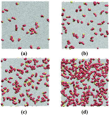 |
| | Fig. 2 Top view snapshots of HT5 surfactants at different surface concentrations of (a) Γ = 0.0098, (b) 0.0196, (c) 0.0392 and (d) 0.0784σ−2; remaining thermodynamic conditions as for Fig. 1. Yellow and red spheres stand for H and T beads, respectively. Grey dots represent w particles. | |
These qualitative observations can be quantified by number density profiles for different species as shown in Fig. 1b, where ns (red dashed-line) represents the number density of the surfactant center-of-masses. The surfactant center-of-mass profile is peaked at the interfacial regions and vanishes in the two bulk phases, verifying the observation that the system is forming insoluble Langmuir monolayers.8 The water density nw profile indicates uniform densities in the bulk phases (with average values of ρl = 0.8569 ± 0.0002σ−3 and ρv = 0.0063 ± 0.0002σ−3) and is slightly peaked at both interfaces due to the higher value of the attraction coefficient cwH than cww beads. The water particles thus prefer H particles as neighbors rather than their own species. This fact can be inferred from radial distribution functions of H–w and w–w pairs and hydration numbers of H groups and w particles given in Fig. S1 of the Section S1.1 (ESI†). The peak in the total particle number density np is even more pronounced due to the adsorption of the H and T monomers at the interface plane.
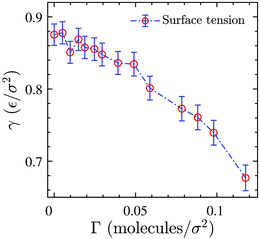
Surface tension γ is calculated employing its standard definition.32 For a 3D periodic system with two planar interfaces normal to the z-direction, the expression takes the form
| |  | (3) |
where 〈⋯〉 denotes the canonical ensemble average and
Pxx,
Pyy and
Pzz are diagonal components of the pressure tensor. The surface tension isotherm of the system evaluated from
eqn (3)via its virial expression for constant
T and varying surfactant concentration is depicted in
Fig. 3. The data shows that
γ decreases by increasing the surface concentration in the range we have examined. We note that the values of the surface tension are slightly different from what was reported by Tomassone
et al.8 for a system with the same interaction potentials at the same state point. The discrepancy is most probably due to finite-size effects, the number of particles in our present study is almost one order of magnitude larger. Furthermore, in contrast to these authors we do not observe a statistically relevant plateau in the surface tension-area isotherm whose presence would signal the phase coexistence regime. The observation of a phase transition is known to be impossible in the simulation of small-sized monolayers,
22 especially in full 3D simulations where one needs to consider a relatively large number of solvent particles to just create a gas–liquid or liquid–liquid interface.
 |
| | Fig. 3 Surface tension as a function of surface concentration for the 3D reference system. Dash-dotted line is just a guide for the eye. | |
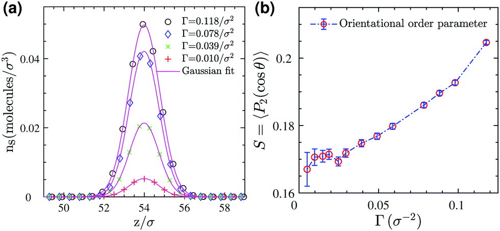
Next, we analyze the surfactant monolayer itself more closely by investigating the surfactant center-of-mass density profile and bond uniaxial orientational order parameter S ∈ [−0.5, 1] in the vicinity of the 2D interface, where the latter is defined as
| |  | (4) |
Here
P2 is the second Legendre polynomial and
θ the polar angle between an individual bond within a surfactant molecule and the
z-direction normal to the 2D interface. The density profiles in
Fig. 4a show that the surfactant center-of-masses are confined within a narrow region at the interface with quite a small thickness roughly of the size of the stretched surfactant end-to-end distance (≈5
σ). Furthermore, the bond order parameter
S, illustrated in
Fig. 4b, shows a weak orientational ordering within the surface concentration range we have examined. Therefore, in this regime we neglect orientational ordering effects and apply our recently developed approach
26 to map the entire 3D system to an effective 2D simple fluid of surfactant center-of-masses.
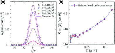 |
| | Fig. 4 (a) Number density profiles of surfactants (based on the position of their center-of-masses) at different surface concentrations (symbols) and Gaussian fits (solid lines) for the 3D reference system. (b) Bond orientational order parameter for surfactants adsorbed at the monolayer as a function of surface coverage. | |
3 Coarse-grained interaction potential
The 3D reference simulations can be used to extract the effective interaction between surfactants within the monolayer constituting the 2D interface. To this end we first consider a simple free energy argument that involves only an effective hard disc diameter for the adsorbed surfactants at the interface plane. Afterwards, we discuss in detail the multiscale coarse-graining procedure to systematically map the whole 3D system to an effective 2D system described by an effective interaction potential.
3.1 Mapping to an effective two-dimensional hard disc fluid
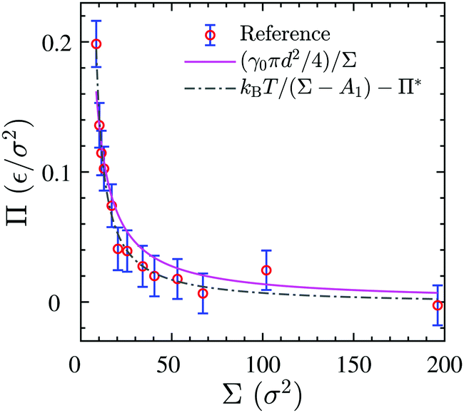
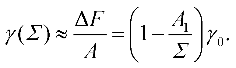
We use the surface pressure–area isotherm to determine an effective disc diameter d of surfactants adsorbed at the 2D interface. Fig. 5 (symbols) shows the surface pressure Π as a function of area per molecule, Σ = A/Nint = 1/Γ, defined bywhere γ0 denotes the surface tension of the bare interface and Nint is the total number of surfactants adsorbed at the assumed flat interface with area A = LxLy.
 |
| | Fig. 5 Surface pressure–area isotherm of the 3D reference simulations (circular symbols), the theoretical fitting of eqn (8) (solid line) and fitting to the Volmer equation of state, eqn (9) (dash-dotted line). | |
In order to rationalize Fig. 5, we employ a simple argument first advocated by Pieranski35 for colloids and later used for polymers.36,37 Each effective surfactant molecule removes an area A1 = πd2/4 from the bare vapor–liquid interface, where d is an effective diameter. The resulting change of free energy can be approximated by
and a corresponding surface tension thus approximately given by
| |  | (7) |
The surface pressure resulting from
eqn (5) and (7) is found to be inversely proportional to the area per molecule,
| | 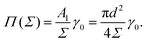 | (8) |
Despite its simplicity,
eqn (8) can describe the results of the simulated surface pressure–area isotherm with an effective diameter
d = 1.41 ± 0.09
σ reasonably well, as shown by the solid line in
Fig. 5. We note that this simple free energy analysis neglects (possible) attractive interaction potentials between the hard discs. In order to consider that, we fit the surface pressure–area data to the commonly used Volmer equation of state
17 for 2D gaseous insoluble monolayers as
| |  | (9) |
where
Π* is the cohesion pressure which accounts for the attraction between hard discs. As it is shown in
Fig. 5 by the dash-dotted line,
eqn (9) describes the simulation results very accurately with an effective diameter of
dVol. = 2.2 ± 0.1
σ and a cohesion pressure of
Π* = 0.002 ± 0.005
ε/
σ2 as fitting parameters. This fitting estimates a somewhat larger hard disc diameter and suggests the existence of an attractive interaction potential between the hard discs. We will compare the values of
d and
dVol. later to an alternative definition of an effective hard core diameter.
3.2 Multiscale coarse-graining
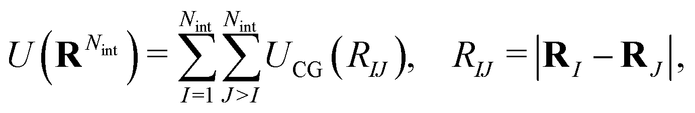
We now discuss the multiscale coarse-graining of the 3D system containing the monolayer and its surrounding to an effective 2D system carrying the potentially phase-separating monolayer. More details are available in our previous study.26 Here we focus on aspects of relevance for the present manuscript. Within this approach one defines Nint CG sites RI as surfactant center-of-masses projected onto the xy-plane described by a mapping MRI, more formally,| | | RI = MRI(rn), I = 1,…, Nint, | (10) |
where rn denotes the position vectors of all particles in the 3D reference system and Nint is the total number of surfactants adsorbed at one monolayer. Since the mass of all beads within the surfactants was chosen to be identical, the mapping operator takes the form| |  | (11) |
where (î, ĵ, ![[k with combining circumflex]](https://www.rsc.org/images/entities/b_char_006b_0302.gif) ) denote Cartesian unit vectors with the surface normal, rsIj denotes the position vector of the jth bead within the Ith surfactant and Nb is the total number of beads of the surfactant chain. Note that the mapping (11) ignores the height of the surfactant center-of-mass which is justified in view of the small interface width (see Fig. 4a). We follow ref. 38 and require consistency between coarse-grained and molecular-level descriptions of the corresponding configurations, RNint = {R1,…, RNint} and rn in the canonical ensemble,
) denote Cartesian unit vectors with the surface normal, rsIj denotes the position vector of the jth bead within the Ith surfactant and Nb is the total number of beads of the surfactant chain. Note that the mapping (11) ignores the height of the surfactant center-of-mass which is justified in view of the small interface width (see Fig. 4a). We follow ref. 38 and require consistency between coarse-grained and molecular-level descriptions of the corresponding configurations, RNint = {R1,…, RNint} and rn in the canonical ensemble,| | 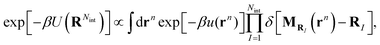 | (12) |
where U(RNint) and u(rn) are the CG and reference total potential energy, respectively, and β = 1/kBT. eqn (12) implies that (i) the coarse-grained potential U(RNint) can be determined up to an additive constant by the reference potential and the mapping operator, and (ii) it is a function of temperature and surface concentration through its dependence on Nint. We follow common practice39 and assume a pairwise interaction potential UCG, which due to symmetry within the interface plane is a central potential resulting in a radial pairwise force strength as| | 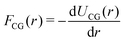 | (13) |
between CG sites. The total potential energy of the coarse-grained system is therefore given by| | 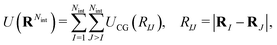 | (14) |
and the coarse-grained force exerted on the Ith projected surfactant center-of-mass reads| |  | (15) |
The force matching scheme38,39 amounts to determining the coarse grained forcefield FCG(r) from underlying 3D reference simulations by minimizing the residual| |  | (16) |
where 〈⋯〉 denotes the canonical expectation value and fI is the net force exerted on the Ith surfactant center-of-mass, projected onto the xy-plane. Implementation details of the force matching scheme are provided in the Section S1.2 (ESI†).
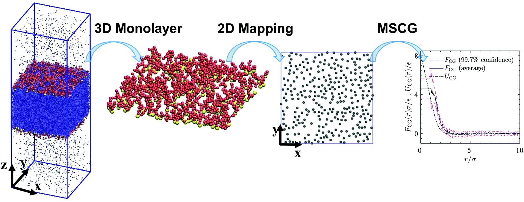
Schematic Fig. 6 shows the entire multiscale coarse-graining process: the mapping operator takes the HT5 surfactants and projects their center-of-masses onto the xy-plane; the corresponding forcefield is subsequently calculated through the force matching scheme. The CG interaction potential obtained from integrating FCG(r) is shifted such that UCG(r) vanishes at r = 10σ (see Section S1.2, ESI†). Fig. 7a shows the results of multiscale coarse-graining for UCG(r) at different surface concentrations. The shown results imply that the effective interaction potential has a soft repulsive core, and an attractive tail begins to appear at smaller surface concentrations. Furthermore, at smaller surface concentrations, its dependency is weaker. A similar behavior for the effective interaction potential has been observed in our previous study26 for surfactants with a different architecture adsorbed at a liquid–liquid interface.
 |
| | Fig. 6 A 3D snapshot, surfactant monolayer and surfactant center-of-masses projected onto the xy-plane for a system consisting of 600 HT5 surfactants at a surface concentration of Γ = 0.118σ−2. Blue dots, yellow and red spheres stand for w, H and T particles respectively. Gray discs represent surfactant center-of-masses within the 2D interface, where a gas–liquid phase transition may occur. The right-hand-side graph shows the forcefield, its confidence intervals and the coarse-grained interaction potential (solid, dashed and dash-dotted lines respectively) obtained from multiscale coarse-graining. | |
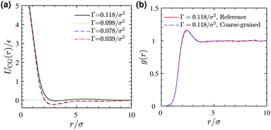 |
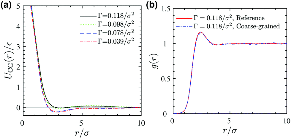
| | Fig. 7 (a) Coarse-grained interaction potential at different surface concentrations Γ. (b) A comparison between pair correlation functions of (i) projected surfactant center-of-masses obtained from 3D reference simulations and (ii) the corresponding 2D coarse-grained system obtained from 2D Monte Carlo simulation, both at a surface concentration of Γ = 0.118/σ2. | |
To test the validity of the pairwise additivity assumption for CG interaction potentials and the accuracy of our force matching calculations, we have performed Monte Carlo simulations using the Metropolis scheme40 for the corresponding two-dimensional coarse-grained systems. Fig. 7b shows a comparison between the radial distribution functions of (i) the projected surfactant center-of-masses obtained from the 3D reference simulation and (ii) the CG sites obtained from a 2D MC simulation, both for a system with a surface concentration of Γ = 0.118σ−2. The agreement is excellent, which validates our assumptions and force matching calculations. Excellent agreement between the pair correlation functions is also observed for the lower surface concentrations we examined (not shown).
The statistical mechanical foundation of the CG interaction potential defined by eqn (12) implies that UCG depends on the state point (T, Γ), as we confirmed by showing its dependency on Γ in Fig. 7a. One can perform 3D reference simulations for different surface concentrations and can construct UCG(r; Γ, T) over a range of concentrations and temperatures as we did in our previous study.26 Because the gas–liquid phase transition of Langmuir monolayers takes place at relatively low surface concentrations, and because we are exploring a new approach to determine the phase equilibrium of a model Langmuir monolayer for the first time, here we adopt the CG interaction potential evaluated at the lowest studied surface concentration and neglect its dependence on surface concentration and temperature in this relatively narrow parameter range. This way we can employ standard GEMC simulations and well-established liquid state theories. These approximations need to be carefully reviewed in future studies.
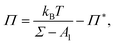
4 Gas–liquid phase transition of the monolayer
In this section, we investigate the 2D gas–liquid expanded phase transition of the monolayer for the CG interaction potential evaluated at Γ = 0.039/σ2 using an “approximate” density functional theory and “exact” Monte Carlo simulations in the Gibbs ensemble.
4.1 Gibbs ensemble Monte Carlo (GEMC)
The Gibbs ensemble technique31 is a method to directly determine the phase coexistence properties of a system at fixed temperature from a single computer simulation with a relatively small number of ≈1000 particles. A system in the canonical ensemble is considered which consists of two periodic 2D simulation regions, one of them carrying the 2D liquid-expanded phase, the other the 2D gas phase, without a direct gas–liquid dividing line. These two subsystems can exchange particles and change their areas such that| | | Ale + Ag = A and Nle + Ng = N | (17) |
where N is the total number of particles and A is the total area, and the values with superscripts le and g correspond, respectively, to those in the liquid-expanded and gaseous subsystems. The equilibrium condition requires the temperature, chemical potential and surface pressure to be equal in the two coexisting phases, originally derived by J. W. Gibbs as27,31| | | Tle = Tg, μle = μg and Πle = Πg. | (18) |
Three different trial moves are performed in the MC simulation of the combined system to satisfy coexistence conditions in eqn (18) subject to constraints eqn (17): (i) independent particle displacements within simulation regions le and g, (ii) area exchange and (iii) particle exchange between the two regions. While exhaustive details of the Monte Carlo simulations in the Gibbs ensemble can be found in ref. 27 and 31, we have collected the most important aspects together with technical details in the Section S2 (ESI†).
Snapshots of the GEMC simulation of the 2D gaseous and liquid phases coexisting at T = 0.46ε/kB and their corresponding pair correlation functions are shown in Fig. 8. The pair correlation function of the gas phase shows only one peak exactly at the same radial distance where the minimum happens for the CG interaction potential (Fig. 7a), whereas the liquid phase is more structured and one can identify second-nearest neighbor peaks.
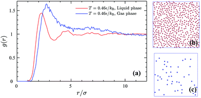 |
| | Fig. 8 Pair correlation functions (a) of the 2D gas phase (blue line) and the liquid phase (red line) and the corresponding simulation snapshots of the liquid phase (b) with the density of ρle = 0.1693σ−2 and the gas phase (c) with the density of ρg = 0.0190σ−2 coexisting at T = 0.46ε/kB. | |
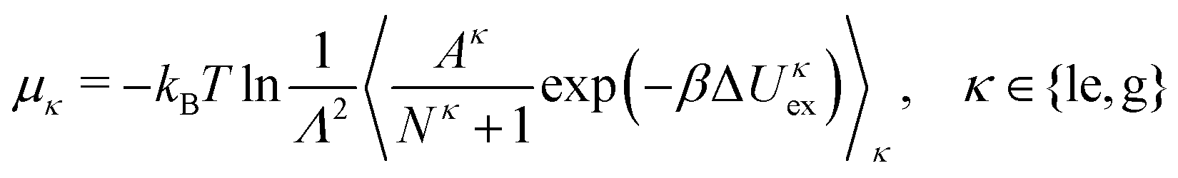
The particle exchange move in the GEMC simulation provides us with the two chemical potentials μle and μg without any additional cost through
| |  | (19) |
where Δ
Uκex is a test particle energy,
Λ is the thermal de Broglie wavelength, and 〈⋯〉
κ denotes the restricted expectation value for subsystem
κ. The surface pressures
Πle and
Πg in the two subsystem can also be obtained from the virial theorem as
41| | 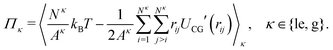 | (20) |
We note that we ignore here a correction term to
eqn (20) due to the density-dependence of
UCG.
26 The densities, surface pressures and chemical potentials of the two coexisting phases obtained from GEMC simulations will be compared with the results of DFT calculations in the following section.
4.2 Density-functional theory (DFT)
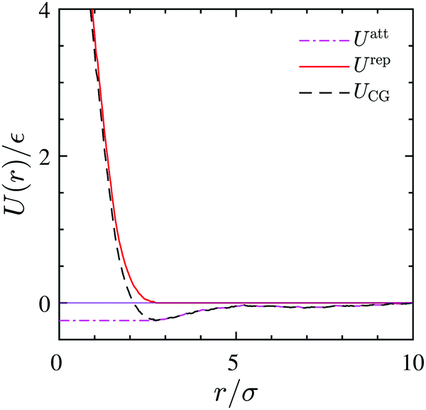
The coarse-grained sites representing the surfactant center-of-masses interact within the 2D interface via a pairwise interaction potential UCG(r) which consists of both, short-range repulsive and attractive branches at large intermolecular distances. We use the Weeks–Chandler–Anderson scheme42 and divide UCG into a repulsive reference part, Urep(r), and an attractive contribution, Uatt(r). They are shown in Fig. 9 and are defined by| | 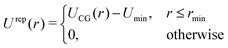 | (21) |
and| |  | (22) |
where rmin denotes the energetically preferred distance, where Umin = UCG(rmin).
 |
| | Fig. 9 CG interaction potential (dashed-line) and its attractive (dash dotted-line) and repulsive branches (solid line) as obtained from the 3D reference simulation at Γ = 0.039/σ2. | |
We follow ref. 30 and define a family of intermediate interaction potentials via
| | | Uλ(r) = Urep(r) + λUatt(r), 0 ≤ λ ≤ 1, | (23) |
where increasing
λ from 0 to 1 corresponds to the gradual increase of the attractive tail and hence a linear change from a repulsive reference system characterized by
Urep to the system of interest characterized by
UCG. The 2D systems's intrinsic Helmholtz free energy
![[scr F, script letter F]](https://www.rsc.org/images/entities/char_e141.gif)
[
ρ] is a functional of the system areal density
ρ(
r) and is exactly given by
30| | 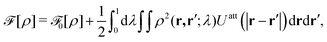 | (24) |
with the Helmholtz free energy
0 of the repulsive 2D reference system described by
U0 =
Urep, while
ρ2(
r,
r′;
λ) is the pair areal density of the system in which particles interact with
Uλ according to
eqn (23). This pair density is not known in general for inhomogeneous systems,
43,44 but it is related to the radial distribution function
g(
r,
r′;
λ) through
ρ2(
r,
r′;
λ) =
g(
r,
r′;
λ)
ρ(
r)
ρ(
r′) and within the random phase approximation (RPA)
43–47 given by
| | | ρ2(r,r′;λ) ≈ ρ(r)ρ(r′). | (25) |
The RPA ignores all correlations between particles and is assumed to work quite well for weakly inhomogeneous systems such as gas–liquid interfaces
43–47 away from the critical region. To calculate the free energy
0[
ρ] of the repulsive 2D reference system, we use the Barker–Henderson (BK) scheme
48 which approximates
0[
ρ] by
| | 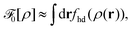 | (26) |
thus employing the free energy areal density
fhd(
ρ) of a system of hard disks with temperature-dependent diameter
dBH given by
48| | 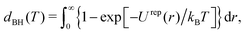 | (27) |
and visualized in Fig. S2 (ESI
†). A local density approximation (LDA) is used in
eqn (26) which is suitable for weakly inhomogeneous systems,
e.g., for liquid–gas interfaces.
43,44 We have calculated the effective hard-disc diameter at
T = 0.9
ε/
kB from
eqn (27) as
dBH = 1.816 ± 0.009
σ which is of the same order but somewhat between the values obtained in Section 3.1 through fitting
eqn (8) and (9) to the results of the
Π–
A isotherm (
Fig. 5).
To summarize, the Helmholtz free energy functional, [ρ], after combining eqn (24)–(26) can be approximated as43,44
| | 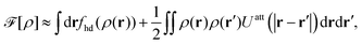 | (28) |
where all integrals extend over the domain of the 2D interface.
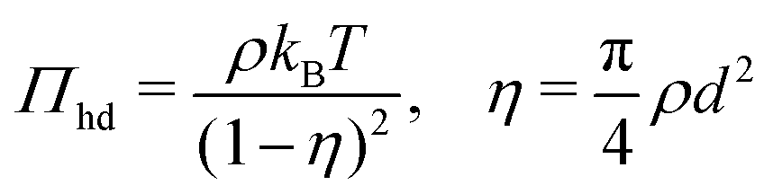
To calculate the required thermodynamic property fhd of the hard disc fluid we have used the hard disc equation of state49
| | 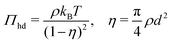 | (29) |
involving the packing fraction
η of hard discs. Using this equation of state, the chemical potential of hard disc fluid,
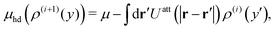
μhd, is described as
| | 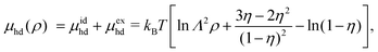 | (30) |
and the free energy density of the hard disc fluid,
fhd = −
Πhd +
ρμhd, is obtained as
| | 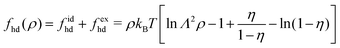 | (31) |
This expression can be substituted into
eqn (28) to estimate
0(
ρ) of the repulsive 2D reference system. In the homogeneous limit of position-independent
ρ(
r), the Helmholtz free energy functional
[
ρ] given by
eqn (28) can be cast into the following form
[
ρ] ≈
Af(
ρ) with the free energy areal density
f(
ρ) given by
| | 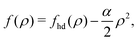 | (32) |
where
α is determined by the available
Uatt(
r),
| |  | (33) |
The corresponding chemical potential and surface pressure in the uniform limit are given by
| |  | (34) |
and
| |  | (35) |
Eqn (34) and (35) are the main relationships used next to determine the gas–liquid coexistence densities and the chemical potential. At a given temperature T the coexisting densities ρle and ρg minimizing [ρle] + [ρg] are the nontrivial solutions (ρle ≠ ρg) of the equation43–47
and
| | | μ(ρle(T)) = μ(ρg(T)), | (37) |
which are solved numerically for
ρle(
T) and
ρg(
T) (see Section S3.3, ESI
†) and then provide us with a unique
μle(
T) =
μg(
T) =
μ(
ρle(
T))
etc. for comparison with the GEMC results for
μle(
T) and
μg(
T).
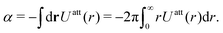
4.3 Comparison between DFT estimates and GEMC results
Fig. 10 displays the phase diagram of the 2D fluid of surfactant center-of-masses obtained from DFT against the results of 2D GEMC simulations. The phase diagram consists of gaseous and liquid phases at temperatures above the critical temperature Tc and their coexistence region below Tc. It shows that DFT predicts semi-quantitative results for the coexisting areal densities with more accurate values for the vapor branch than the liquid branch.50 To estimate the critical point (ρc,Tc) from GEMC simulations, we fit the density difference of the coexisting phases to the scaling law27,28,31,32 as| | | ρle − ρg ∝ (T − Tc)β, | (38) |
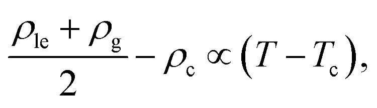
where the critical temperature and the critical exponent are obtained as Tc = 0.548 ± 0.005ε/kB and β = 0.31 ± 0.01 respectively. Note that this exponent β is not equal to the corresponding critical exponent of the 2D Ising model and is in fact much closer to that of the 3D one. In order to estimate the critical exponent and the critical temperature more properly, knowledge of interaction potentials UCG(r; Γ, T) over the examined temperature and areal density ranges, and finite-size scaling analyses are necessary. We further fit the results of the GEMC simulations to the law of rectilinear diameters,27,28,31,32| |  | (39) |
and estimate the value of the critical density as ρc = 0.087 ± 0.001σ−2.
 |
| | Fig. 10 Phase diagram of the 2D fluid described by UCG in Fig. 9 obtained from DFT (solid line) and GEMC simulations (open circles). The left branches correspond to the gaseous phase and the right ones correspond to the liquid phase. The critical point (filled circle) is estimated by fitting GEMC results to the scaling law and the law of rectilinear diameters. | |
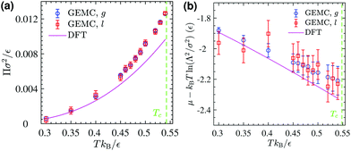
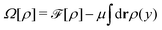
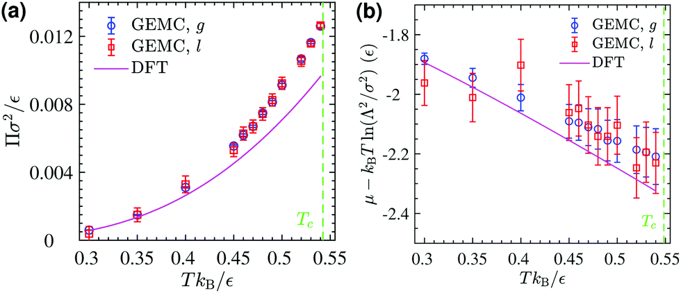
The corresponding DFT estimates for the surface pressure and chemical potential at coexistence are plotted in Fig. 11 against the results of the GEMC simulations, obtained from ensemble averages described by eqn (19) and (20). The fact that the chemical potentials and pressures of the gaseous and liquid expanded phases in the GEMC simulations are equal within statistical errors validates the accuracy of our MC simulations and the sampling of equilibrium configurations. The DFT result (solid lines in Fig. 11b) for the chemical potential is in a good agreement with the result of the GEMC simulations. The agreement of the surface pressure (Fig. 11a) is very good at low temperatures T ≤ 0.35ε/kB but becomes increasingly inaccurate as T gets closer to the critical point. As is obvious from Fig. 10, and in part due to the approximations involved, the critical point resulting from the DFT calculation is located at a higher T and smaller ρ compared with the GEMC result.
 |
| | Fig. 11 (a) GEMC results for the surface pressure in the liquid phase (open squares) and the gas phase (open circles) within the coexistence region below Tc. The solid line shows the pressure at coexistence obtained from DFT for comparison. (b) GEMC results for the chemical potential in the liquid phase (open squares) and the gas phase (open circles). The solid line shows its value at coexistence obtained from DFT. | |
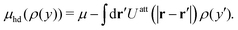
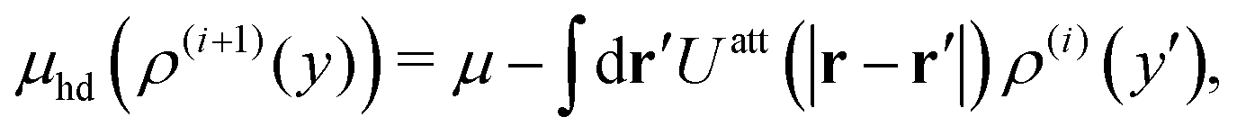
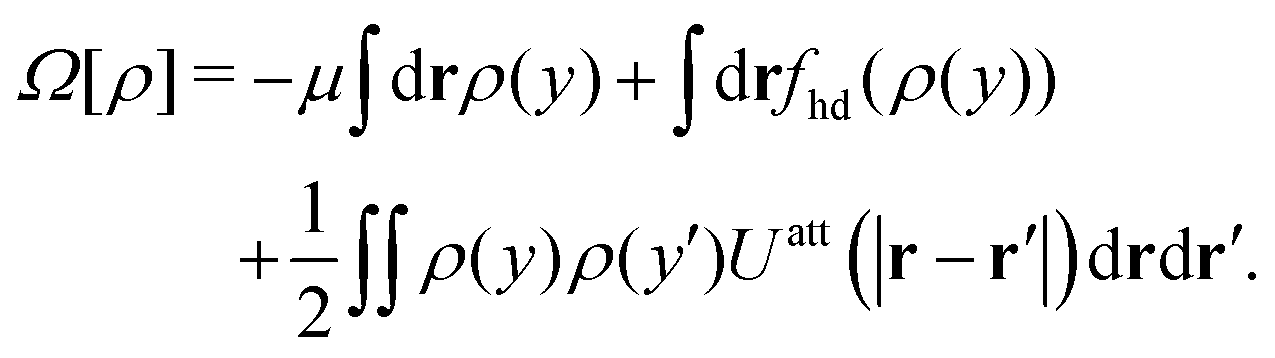
Apart from calculating the areal densities, surface pressure, chemical potential, and free energy at coexistence, the form of the density profile across the gas–liquid expanded dividing line and the line tension can also be determined from DFT.44–47 The grand potential of an inhomogeneous monolayer with density variations in the y-direction is given by
| |  | (40) |
where
μ =
μ(
T) is the chemical potential at coexistence (obtained from solving
eqn (36) and (37) simultaneously), and is constant throughout the system under the equilibrium condition. The equilibrium density profile
ρ(
r) fulfills the following variational condition
30,43–45| |  | (41) |
As a consequence, the density profile
ρ(
y) normal to the gas–liquid expanded dividing line defining the
x-axis must fulfill the following integral equation
| |  | (42) |
where
y and
y′ denote the transverse components of
r and
r′ with respect to the 1D phase boundary.
Eqn (42) is self-consistently solved for
ρ(
y) by considering an initial density profile
ρ(0)(
y) and applying an iterative procedure
44–47 as
| |  | (43) |
until convergence has been reached, where
ρ(i+1) and
ρ(i) represent the
i + 1 and
ith iterations respectively (see Section S3.4, ESI
†). The procedure is repeated for every
T separately, and a profile
ρ(
y) obtained at a given temperature can serve as an initial
ρ(0)(
y) for a subsequent
T.
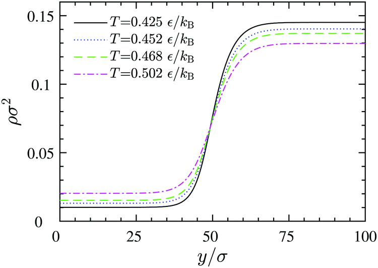
The resulting density profiles across gas–liquid expanded dividing lines at different temperatures (Fig. 12) can be fitted very accurately to a hyperbolic tangent profile51
| | 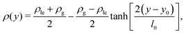 | (44) |
where
l0 =
l0(
T) is the width of the dividing line region and
y0 represents the position of the equimolar dividing line. This procedure reveals that by increasing the temperature, the thickness increases and the dividing line region becomes more diffuse: while at
T = 0.425
ε/
kB the thickness is
l0 = 12.88 ± 0.14
σ, at the higher
T = 0.502
ε/
kB we obtain
l0 = 16.52 ± 0.09
σ within the DFT approach.
 |
| | Fig. 12 Density profiles across equilibrium gas–liquid dividing lines at different temperatures, obtained via DFT. The left and the right plateaus correspond to the 2D gas and liquid bulk densities, respectively. | |
The grand potential of the inhomogeneous 2D system can now be determined by plugging the DFT equilibrium density profile, ρ(y), into eqn (40) and using eqn (28) as
| |  | (45) |
where, for example,
with
L denoting the length of the dividing line, and

representing the total number of particles within the monolayer, which drops out from the DFT calculations. Now we have all ingredients to calculate the line tension of the gas liquid-expanded dividing line as
46| | 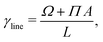 | (46) |
where
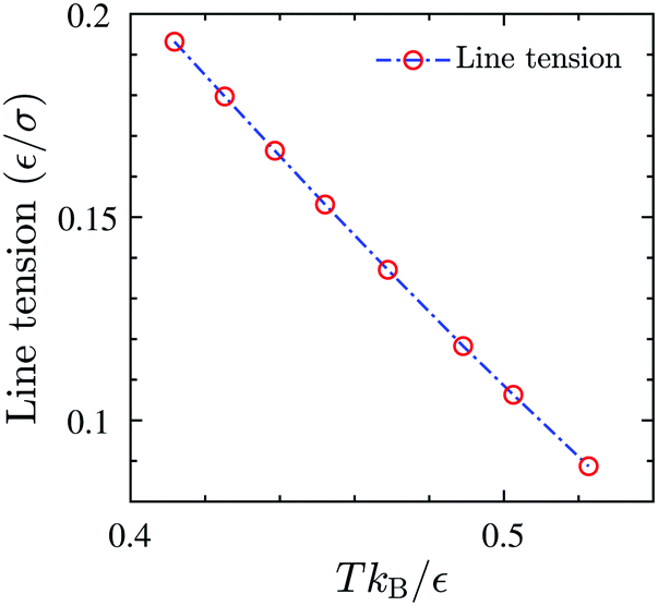
A is the total area of the gas and liquid expanded phases together. The results of the gas–liquid line tension at different temperatures are shown in
Fig. 13. The line tension decreases monotonically by increasing the temperature,
46 and should in principle vanish at the critical point where there is no distinction between liquid and gas phases.
50 The results of the grand potential and line tension can also be used to investigate 2D gas liquid-expanded nucleation for the surfactant monolayer, see
e.g. Zeng,
46 Zeng and Oxtoby.
47
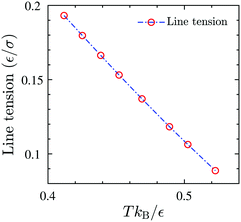 |
| | Fig. 13 The equilibrium gas–liquid line tension of the 2D fluid of surfactant center-of-masses, obtained via DFT, as a function of temperature. The line tension vanishes at the critical Tc predicted by DFT. | |
5 Conclusions
Exploring G-LE phase transitions of Langmuir monolayers is extremely time-consuming via finite-size 3D molecular simulations. Starting out with MD simulations of a 3D reference model system containing a monolayer of insoluble surfactants at the vapor–liquid interface, we determined the effective lateral interaction potentials between surfactant center-of-masses at the interface. MC simulations of the resulting 2D systems show that these effective interaction potentials are quite successful in predicting pair correlation functions (and hence the structure) of surfactant center-of-masses projected onto the interface plane.
At relatively small surface concentrations, the effective interactions exhibit an attractive tail suggesting that in principle a gas–liquid expanded phase transition can take place within the monolayer. For the effective 2D (simple) fluid of surfactant center-of-masses, described by these CG interaction potentials, we performed GEMC simulations and DFT calculations to investigate the 2D gas–liquid phase equilibrium, while these interactions could also be used to perform 2D simulations for large system sizes, and to explore large-scale self-assembly and domain formation within the monolayer. The DFT results for coexisting areal densities, surface pressure, and chemical potential are in semi-quantitative agreement with those of the GEMC simulations.
We have illustrated and applied these procedures for a system at a relatively small surface concentration, where we neglect the dependence of UCG on surface concentration Γ and temperature T. As a next step, it would be desirable to determine the CG interaction potential over a concentration range and construct UCG(r; Γ, T)26 at different temperatures. Then it is relatively straightforward to perform GEMC simulations for density-dependent interaction potentials, as discussed by Smith et al.52 The complexity of the DFT calculations remains unchanged upon varying Γ and T. Such studies would then allow to evaluate the effect of the density- and temperature-dependence of UCG on the phase behavior, line tension, and density profiles.
Here we employed as a reference system a linear bead-spring model representing surfactants at the vapor–liquid interface of a monoatomic Lennard-Jones solvent.8 The presented scheme can be applied straightforwardly to other surfactant architectures such as branched phospholipids. Such effort could enable us to resolve the effect of molecular interactions and surfactant architecture on their phase behavior.
Conflicts of interest
There are no conflicts to declare.
Acknowledgements
This work was supported by the Swiss National Science Foundation through Grant No. 200021_156106. P. I. acknowledges support from EU FP7-MC-CIG Grant No. 631233. The authors thank Hans Christian Öttinger for the helpful discussions as well as critical reading of the manuscript.
References
- V. M. Kaganer, H. Möhwald and P. Dutta, Rev. Mod. Phys., 1999, 71, 779–819 CrossRef CAS.
- C. M. Knobler and R. C. Desai, Annu. Rev. Phys. Chem., 1992, 43, 207–236 CrossRef CAS.
- H. Möhwald, Thin Solid Films, 1988, 159, 1–15 CrossRef.
- M. L. Schlossman and A. M. Tikhonov, Annu. Rev. Phys. Chem., 2008, 59, 153–177 CrossRef CAS PubMed.
- E. M. Scarpelli, Anat. Rec., 1998, 251, 491–527 CrossRef CAS PubMed.
- S. Roke, J. Schins, M. Müller and M. Bonn, Phys. Rev. Lett., 2003, 90, 128101 CrossRef PubMed.
- D. Vollhardt and V. Fainerman, Adv. Colloid Interface Sci., 2006, 127, 83–97 CrossRef CAS PubMed.
- M. S. Tomassone, A. Couzis, C. M. Maldarelli, J. R. Banavar and J. Koplik, J. Chem. Phys., 2001, 115, 8634–8642 CrossRef CAS.
- J. I. Siepmann, S. Karaborni and M. L. Klein, J. Phys. Chem., 1994, 98, 6675–6678 CrossRef CAS.
- V. Knecht, M. Müller, M. Bonn, S.-J. Marrink and A. E. Mark, J. Chem. Phys., 2005, 122, 024704 CrossRef.
- R.-Y. Tsay, T.-F. Wu and S.-Y. Lin, J. Phys. Chem. B, 2004, 108, 18623–18629 CrossRef CAS.
- M. M. Hossain, T. Suzuki, K.-I. Iimura and T. Kato, Langmuir, 2006, 22, 1074–1078 CrossRef CAS.
- P. J. Winch and J. C. Earnshaw, J. Phys.: Condens. Matter, 1989, 1, 7187 CrossRef CAS.
- D. Vollhardt, V. B. Fainerman and S. Siegel, J. Phys. Chem. B, 2000, 104, 4115–4121 CrossRef CAS.
- Y. Y. Zuo, R. Chen, X. Wang, J. Yang, Z. Policova and A. W. Neumann, Langmuir, 2016, 32, 8501–8506 CrossRef CAS.
- J. Israelachvili, Langmuir, 1994, 10, 3774–3781 CrossRef CAS.
- V. B. Fainerman, D. Vollhardt and V. Melzer, J. Phys. Chem., 1996, 100, 15478–15482 CrossRef CAS.
- D. Vollhardt and V. B. Fainerman, J. Phys. Chem. B, 2002, 106, 345–351 CrossRef CAS.
- V. B. Fainerman and D. Vollhardt, J. Phys. Chem. B, 1999, 103, 145–150 CrossRef CAS.
- C. M. Knobler, Adv. Chem. Phys., 1990, 77, 397 CAS.
- V. M. Kaganer and E. B. Loginov, Phys. Rev. E: Stat. Phys., Plasmas, Fluids, Relat. Interdiscip. Top., 1995, 51, 2237–2249 CrossRef CAS.
- S. Baoukina, L. Monticelli, S. J. Marrink and D. P. Tieleman, Langmuir, 2007, 23, 12617–12623 CrossRef CAS PubMed.
- P. Yazhgur, S. Vierros, D. Hannoy, M. Sammalkorpi and A. Salonen, Langmuir, 2018, 34, 1855–1864 CrossRef CAS.
- L. Villalobos, Y. M. López-Álvarez, B. Pastrana-Ríos and G. E. López, J. Chem. Phys., 2005, 122, 104701 CrossRef.
- J. J. Giner-Casares, L. Camacho, M. T. Martín-Romero and J. J. L. Cascales, Langmuir, 2008, 24, 1823–1828 CrossRef CAS.
- A. Moghimikheirabadi, L. M. C. Sagis and P. Ilg, Phys. Chem. Chem. Phys., 2018, 20, 16238–16246 RSC.
- A. Z. Panagiotopoulos, Mol. Phys., 1987, 61, 813–826 CrossRef CAS.
- B. Smit and D. Frenkel, J. Chem. Phys., 1991, 94, 5663–5668 CrossRef CAS.
- E. Ramírez, A. Santana, A. Cruz and G. E. López, J. Chem. Phys., 2007, 127, 224703 CrossRef.
-
J.-P. Hansen and I. R. McDonald, in Theory of Simple Liquids, ed. J.-P. Hansen and I. R. McDonald, Academic Press, Oxford, 4th edn, 2013, pp. 61–104 Search PubMed.
-
D. Frenkel and B. Smit, in Understanding Molecular Simulation, Academic Press, San Diego, 2nd edn, 2002, pp. 201–224 Search PubMed.
-
J. Rowlinson and B. Widom, Molecular Theory of Capillarity, Dover Publications, 2002 Search PubMed.
- S. Plimpton, J. Comput. Phys., 1995, 117, 1–19 CrossRef CAS.
- W. G. Hoover, Phys. Rev. A: At., Mol., Opt. Phys., 1985, 31, 1695–1697 CrossRef.
- P. Pieranski, Phys. Rev. Lett., 1980, 45, 569–572 CrossRef CAS.
- L. Isa, E. Amstad, K. Schwenke, E. Del Gado, P. Ilg, M. Kröger and E. Reimhult, Soft Matter, 2011, 7, 7663–7675 RSC.
- Z. A. Zell, L. Isa, P. Ilg, L. G. Leal and T. M. Squires, Langmuir, 2014, 30, 110–119 CrossRef CAS.
- W. G. Noid, J.-W. Chu, G. S. Ayton, V. Krishna, S. Izvekov, G. A. Voth, A. Das and H. C. Andersen, J. Chem. Phys., 2008, 128, 244114 CrossRef CAS.
- W. G. Noid, P. Liu, Y. Wang, J.-W. Chu, G. S. Ayton, S. Izvekov, H. C. Andersen and G. A. Voth, J. Chem. Phys., 2008, 128, 244115 CrossRef CAS.
-
M. P. Allen and D. J. Tildesley, Computer Simulation of Liquids, Clarendon Press, New York, NY, USA, 1989 Search PubMed.
- K. Fuchizaki, J. Phys. Soc. Jpn., 2011, 80, 024003 CrossRef.
- J. D. Weeks, D. Chandler and H. C. Andersen, J. Chem. Phys., 1971, 54, 5237–5247 CrossRef CAS.
- R. Evans, Adv. Phys., 1979, 28, 143–200 CrossRef CAS.
- B. Q. Lu, R. Evans and M. T. da Gama, Mol. Phys., 1985, 55, 1319–1338 CrossRef CAS.
- P. Tarazona and R. Evans, Mol. Phys., 1983, 48, 799–831 CrossRef CAS.
- X. C. Zeng, J. Chem. Phys., 1996, 104, 2699–2704 CrossRef CAS.
- X. C. Zeng and D. W. Oxtoby, J. Chem. Phys., 1991, 94, 4472–4478 CrossRef CAS.
- J. A. Barker and D. Henderson, J. Chem. Phys., 1967, 47, 4714–4721 CrossRef CAS.
- E. Helfand, H. L. Frisch and J. L. Lebowitz, J. Chem. Phys., 1961, 34, 1037–1042 CrossRef CAS.
-
I. Kusaka, Statistical Mechanics for Engineers, Springer International Publishing, 2015, pp. 259–308 Search PubMed.
- J. Walton, D. Tildesley, J. Rowlinson and J. Henderson, Mol. Phys., 1983, 48, 1357–1368 CrossRef CAS.
- B. Smith, T. Hauschild and J. Prausnitz, Mol. Phys., 1992, 77, 1021–1031 CrossRef.
Footnote |
| † Electronic supplementary information (ESI) available. See DOI: 10.1039/c8cp05447a |
|
| This journal is © the Owner Societies 2019 |
Click here to see how this site uses Cookies. View our privacy policy here. 
 Open Access Article
 This Open Access Article is licensed under a
  *a,
Leonard M. C.
Sagis
*a,
Leonard M. C.
Sagis


 was used to integrate modified Hamilton's equations of motion as the temperature was fixed by using a Nosé–Hoover34 thermostat with a damping time of
  . A smaller system with the same interaction potentials at the same state point at T = 0.9ε/kB has been studied previously.8
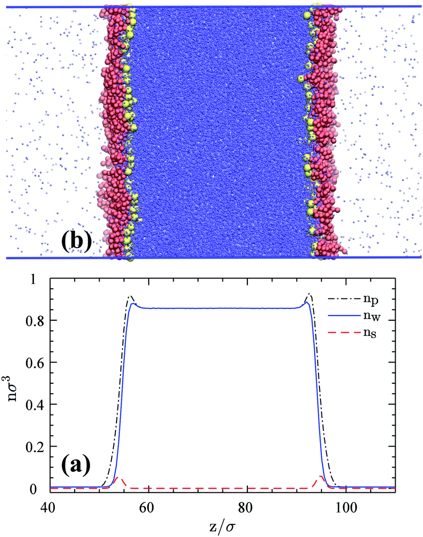


 with L denoting the length of the dividing line, and
  representing the total number of particles within the monolayer, which drops out from the DFT calculations. Now we have all ingredients to calculate the line tension of the gas liquid-expanded dividing line as46