
Aluminium doping – a cost effective and super-fast method for low temperature crystallization of TiO2 nanotubes
Sinitha B.
Nair
a,
Aijo John
K.
a,
Hilal
Rahman
a,
Julie Ann
Joseph
a,
Stephen
K. Remillard
b and
Rachel Reena
Philip
 *a
*a
aDepartment of Physics, Union Christian College, Aluva, Kerala, India. E-mail: reenatara@gmail.com
bDepartment of Physics, Hope College, Holland, MI49423, USA
First published on 30th November 2018
Abstract
In this paper, low-temperature crystallization of well aligned TiO2 nanotubes within a record time of 20 seconds is reported. This new super-fast crystallization route with a tremendous technological impact due to its low energy budget and reproducibility involves the doping of TiO2 nanotubes with aluminium at different temperatures from 2 °C to 60 °C by applying a negative voltage to amorphous nanotubes. The process offers formation of doped anatase TiO2 nanotubes with a tuned band gap and improved conductivity.
1 Introduction
Titanium dioxide (TiO2) nanotubes (TONTs) have been mostly investigated because of their outstanding performance in many photoelectrochemical applications including dye-sensitized solar cells, sensors, and supercapacitors and in photocatalysis and water splitting due to their abundance and non-toxicity.1–4 While TONTs with a narrow band gap and higher charge transfer efficiency are preferred for photocatalytic applications, a wider band gap and good electrical conductivity are suitable for their applications as electrodes in dye sensitized solar cells.5 Hence the tuning of their optical and electrochemical properties is of prime importance while considering their employability in various device fabrication processes. In addition, since amorphous TONTs are not suitable for the above said applications, production of crystalline tubes and control of the nanotube-array morphology are very much important for their application in dye-sensitized solar cells and photocatalysis.6 It is a major challenge to successfully convert the amorphous structure of as-fabricated TiO2 nanotubes to crystalline, while maintaining the barrier layer at a minimal thickness. TONTs fabricated by an electrochemical anodization method are amorphous in nature and so an elevated temperature, typically greater than 450 °C, is required to induce crystallinity.7,8 But the main drawback of this method is that a very high thermal energy budget is needed to attain crystallization. Also this produces a thick barrier layer at the bottom of the nanotubes and it separates nanotube arrays from the substrate resulting in the slowdown of electrons which causes poor performance of devices.9,10 Moreover, a high temperature annealing process is not favourable for the formation of nanotube arrays over temperature sensitive polymeric substrates.11 Crystallization by hydrothermal treatment is not convenient as it results in structural damage.12 Similarly, with sol–gel processes, TiO2 nanoparticles usually exhibit a high tendency to aggregate.13 Therefore recently, researchers have investigated low-temperature methods for crystallization of TONTs to achieve the full benefit of the material properties.14,15In this decade, low-temperature water-assisted treatment to crystallize amorphous TiO2 nanotubes has evoked enormous interest in the scientific community. It is reported that amorphous as-anodized TONTs are immersed in water for 3–4 days at room temperature or in hot water at a temperature near 90 °C for 20 hours to attain an anatase phase.16,17 These methods have the disadvantages of requiring very long incubation time and also the nanotubular structure getting damaged.18–20 Another method for crystallization of TONTs is by treating them with water vapour but in the crystallization process amorphous NTs are converted to nanorod-like structures.12 Aijo et al.21 has reported room temperature crystallization by applying square pulses where crystallization begins to appear within the first five minutes of pulse treatment, leading to high crystallinity of tubes within 15 minutes. A few attempts to attain crystallization by doping TONTs with metal ions are also reported.22,23 Although the doped TONTs exhibit satisfactory properties, they usually suffer from multiple and tedious steps that limit their usage.24–28
Here, we report successful conversion of amorphous TONTs to an anatase phase by a facile and novel method of doping the former with Al in an Al2(SO4)3 electrolyte. This method has the multiple advantages of i) ultrafast conversion of amorphous TONTs to an anatase phase within a record time of 20 seconds without any structural or morphological degradation, ii) achieving tuning of the band gap and electrical conductivity, iii) crystallization at temperatures from 2 °C and iv) reproducibility. To the best of our knowledge, no one hitherto has reported crystallization of TONTs at a temperature below room temperature or at such a fast rate. Hence, this report is of great technological importance especially to those working on TONT applications that require cost effectiveness and low energy budget.
2 Experimental
Low temperature crystallization is attained here by a ‘two-step anodisation’ method. In the first stage, well ordered TONTs are fabricated by the conventional anodisation process at different bath temperatures varying from 2–60 °C, with 0.5 wt% ammonium fluoride and 2 vol% de-ionized water in an ethylene glycol electrolyte as the bath and Ti foil as the anode and cathode. The anodisation voltage is kept at 50 V for 30 minutes for the fabrication of well aligned TONTs and the current density variations with time are monitored. For 2 °C, the current density is found to be decreased from 0.131 to 0.036 A cm−2 within the first 55 seconds, then there is an instantaneous increase in current density to 0.038 A cm−2 and after that steady state current density is achieved. Similar observation with an incremental increase in current density is obtained during the anodisation process at all bath temperatures up to 40 °C. The observations are indicative of the various growth stages involved in the nanotube fabrication.29–34 For 60 °C, the current density is found to be decreased from 0.193 to 0.086 A cm−2 within the first 28 seconds and after that there is a sudden jump to 0.089 A cm−2, but then it continues to increase slightly instead of being steady. The latter may be due to the heat generated during the process. The grown tubes are subjected to nanograss removal before characterization. The doping is carried out in the second stage by using the fabricated TONTs as the cathode and titanium as the anode in 0.5 M solution of an aluminium sulphate electrolyte and by applying a potential of 50 V between the anode and cathode for a constant time of 20 seconds. The schematic representation of the process is shown in Fig. 1. | ||
| Fig. 1 Schematic representation of formation of crystalline TONTs upon Al doping. | ||
The surface morphology of the tubes is studied using a Carl Zeiss Sigma field emission scanning electron microscope (FESEM). Compositional analysis is performed using RBS. The structural properties are studied by XRD using a Bruker D8 Advance X-ray diffractometer, HR-TEM using a Joel JEM 2100, and Raman spectroscopy using a WITec Alpha 300 RA (Nd:YAG) at X = 532 nm Raman wavelength. Further optical and electrical measurements are conducted using a diffuse reflectance spectrometer and a Keithley 2450 source meter with a kickstart interface, respectively.
3 Results and discussion
The surface morphologies of the undoped and Al doped tubes prepared at various temperatures between 2 °C and 60 °C from FESEM are shown in Fig. 2 and 3. It is obvious that in both cases, even at the temperature of 2 °C, nanotube arrays with regular pores are obtained. As the temperature increases, the nanotubular growth rate and diameter increase initially up to 40 °C. Thereafter, there is a decrease in the growth rate and nanotubular diameter as shown in Table 1. The micrographs reveal a perfect tubular structure after Al doping and no Al metal layer is present on the top of the tubes. Fig. 4 shows the measured and simulated RBS spectra of the undoped and Al doped TONTs prepared at 40 °C. The SIMNRA fitting for the undoped samples confirms the presence of Ti and oxygen with an at% ratio of 1![[thin space (1/6-em)]](https://www.rsc.org/images/entities/char_2009.gif) :2 while that for the Al doped samples gives the best fit with Al at% of 2% in the samples. The determination of thickness yields values slightly different from those in FESEM which indicates that ion beam methods needs to be applied to nanotubes very carefully accounting for voids and potential channeling, and this matter is currently under investigation.
:2 while that for the Al doped samples gives the best fit with Al at% of 2% in the samples. The determination of thickness yields values slightly different from those in FESEM which indicates that ion beam methods needs to be applied to nanotubes very carefully accounting for voids and potential channeling, and this matter is currently under investigation.
 | ||
| Fig. 2 FESEM images of pure TONTs prepared at (a) 2 °C, (b) 15 °C, (c) 28 °C, (d) 40 °C and (e) 60 °C. | ||
 | ||
| Fig. 3 FESEM images of Al doped TONTs prepared at (a) 2 °C, (b) 15 °C, (c) 28 °C, (d) 40 °C and (e) 60 °C. | ||
| Temperature (°C) | Average pore diameter (nm) | Average wall thickness (nm) | Length (μm) | |||
|---|---|---|---|---|---|---|
| Undoped | Al doped | Undoped | Al doped | Undoped | Al doped | |
| 2 | 47 | 50 | 20 | 24 | 2.72 | 2.68 |
| 15 | 66 | 63 | 12 | 14 | 4.20 | 4.12 |
| 28 | 80 | 74 | 10 | 12 | 5.10 | 5.05 |
| 40 | 98 | 88 | 6 | 11 | 7.12 | 6.90 |
| 60 | 73 | 76 | 13 | 12 | 2.24 | 2.27 |
 | ||
| Fig. 4 RBS spectra of pure (Fig. a) and Al doped TONTs (Fig. b) prepared at 40 °C. | ||
Fig. 5 shows the X-ray diffraction (XRD) patterns of both undoped and doped titania nanotube arrays fabricated at different bath temperatures. The undoped nanotubes start crystallizing at 40 °C whereas it is noteworthy that the Al doped nanotubes show crystallization in the anatase phase even at the bath temperature of 2 °C. The crystallites are prominently oriented along the [101] direction and the other observable anatase peak is due to diffraction from the spacing corresponding to the (200) plane. The intensity of the diffraction peak enhances obviously with the bath temperature which implies better crystallization at higher temperatures. Xiao et al.29 has reported the appearance of a small anatase peak in their tubes fabricated by anodization at 50 °C taking a duration time of 24 hours. But to date no one has reported any evidence of crystallization in TONTs at or below room temperature, i.e. a temperature at which the crystallization process occurs without any assistance of thermal energy. Here, although the intensity of the (101) plane is found to be maximum for the tubes prepared at 40 °C (slightly heated bath), it is of great technological importance that even without any supply of thermal energy, TONT crystallization is made possible by Al doping. In addition to low thermal budget, superfast crystallization and cost effectiveness, the advantages of reproducibility and ease in being scaled up are further attractions of this technique. The increase in temperature to 60 °C decreases the crystallinity. Various researchers30–34 have observed that the immersion time and bath temperature play a significant role in determining the properties of the nanotubes and the same is also observed in the present case.
 | ||
| Fig. 5 X-ray diffraction images of the 1) undoped and 2) Al doped TONTs at (a) 2 °C, (b) 15 °C, (c) 28 °C, (d) 40 °C and (e) 60 °C. | ||
The transmission electron microscopy (TEM) images of the 2 °C prepared amorphous TONTs and Al doped crystallized TONTs are shown in Fig. 6. The amorphous nature of the undoped TONTs prepared at 2 °C (Fig. 6a) shows a homogeneous maze-like pattern without any detectable fringes. But upon doping them with aluminium, spotted rings are observed in the selected area electron diffraction (SAED) pattern (Fig. 6b and inset) confirming the crystalline nature. Upon increasing the temperature to 28 °C (Fig. 6c) and further to 40 °C (Fig. 6d), spotted rings become more and more intense which confirms the polycrystalline nature of the tubes. The measured d-spacing of 0.35 nm corresponds to the dominant (101) planes of the anatase phase21 and is consistent with our XRD result.
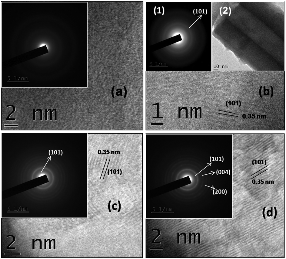 | ||
| Fig. 6 TEM images of the as-prepared samples a) undoped TONTs prepared at 2 °C, b) Al doped TONTs at 2 °C (inset 1: SAED pattern and 2: HR TEM image), c) Al doped TONTs at 28 °C (inset: SAED pattern) and d) Al doped TONTs at 40 °C (inset: SAED pattern). | ||
The Raman spectra of the as-prepared samples (Fig. 7) confirm the anatase TiO2 crystalline nature of the doped nanotubes and the amorphous nature of the undoped ones prepared without any assistance of thermal energy. The Raman spectrum of anatase TiO2 which belongs to the phase group D4h (ref. 19) usually exhibits six vibrational bands at frequencies 144 (Eg), 197 (Eg), 399 (B1g), 519 (A1g + B1g), and 639 cm−1 (Eg).35,36 While no distinct peaks are found for the amorphous samples, four distinguishable peaks (152, 396, 513 and 631 cm−1) are found for the crystalline samples in the present case. The slight shift in the vibrational peak position is indicative of uniform distribution of Al ions in the tetragonal crystal lattice of anatase TiO2. Such shifts due to the incorporation of dopant metals of different ionic radii into TONTs, which produce tensions in the crystalline lattice, are reported.37 The absence of Raman peaks corresponding to any Al species (at 317 cm−1 and 976 cm−1)38 confirms that no other species are present in the prepared Al doped anatase TONTs.
 | ||
| Fig. 7 Raman spectra of the a) amorphous and b) Al doped TONTs at 40 °C. | ||
The Kubelka–Munk function, F(R) = (1 − R)2/2R, which is derived from the reflectance R measured from the diffuse reflectance spectra is used for determining the band gap in each case. It is found from the fits in Fig. 8 that the band gap of undoped TONTs continuously decreases from 2.93 eV to 2.66 eV as the bath temperature is increased from 2 °C to 40 °C, whereas it increases beyond that temperature. The band gap of Al doped TONTs is below that of undoped ones prepared at the corresponding temperature and it further manifests a decrease from 2.87 eV to 2.54 eV as the electrolyte bath temperature is increased from 2 °C to 40 °C, whereas an increase of the band gap to 3.06 eV is observed for the tubes doped at 60 °C.
 | ||
| Fig. 8 [F(R)hν]1/2vs. hν graph of Al doped TONTs at different bath temperatures (a) 2 °C, (b) 15 °C, (c) 28 °C, (d) 40 °C and (e) 60 °C (inset: corresponding to pure TONTs). | ||
The incorporation of Al into the TiO2 lattice must be introducing a dopant energy level below its conduction band that subsequently creates intra-band gap states close to the valence band edges and leads to narrower band gaps.39 This large shift in the bandgap towards the visible region is significant in the application of the nanotubes in photocatalysis.
It is reported that the electrical conductivity of nanotubes depends strongly on the phase and structural quality.40 In the present study, Al doping is found to improve the conductivity of the TONTs by around 3 orders of magnitude as shown in Fig. 9.2. The conductivity changes as 4 × 10⁻⁹ S m−1 → 40 × 10−9 S m−1 → 2.6 × 10⁻⁶ S m−1 → 170 × 10−6 S m−1 → 0.92 × 10⁻⁶ S m−1 with the bath temperature change from 2 °C → 15 °C → 28 °C → 40 °C → 60 °C in undoped TONTs and as 0.20 × 10⁻⁶ S m−1 → 2.1 × 10⁻⁶ S m−1 → 28.5 × 10⁻⁶ S m−1 → 1499.3 × 10−6 S m−1 → 39.3 × 10⁻⁶ S m−1 for the temperature variation 2 °C → 15 °C → 28 °C → 40 °C → 60 °C in doped TONTs.
 | ||
| Fig. 9 1. Voltage vs. current density of Al doped TiO2 nanotubes for different bath temperatures (a) 2 °C, (b) 15 °C, (c) 28 °C, (d) 40 °C and (e) 60 °C; (2) bath temperatures vs. conductivity graph of Al doped TiO2 nanotubes at 2 V (inset: corresponding to pure TONTs). | ||
It is observed that Al doping effectively modifies the electronic properties of TiO2 as the metal ions generate dopant states in the band-gap that enhances the conductivity of TiO2 nanotubes. The very high conductivity attained for pure and Al doped tubes prepared at 40 °C can be attributed to their higher crystallization and the close alignment of well-ordered tubes perpendicular to the substrate surface. The conductivity improvement together with the narrowed band gap is advantageous when the tubes are used in optoelectronic and photocatalytic applications.
It is well known that TiO62− octahedra are basic building blocks of all the phases of TiO2: the amorphous TiO2 and the three crystalline polymorphs (anatase, rutile and brookite), and various researchers have pointed out that crystallization of amorphous tubes is made possible by inducing structural rearrangement of the TiO62− octahedral units upon exposing the tubes to different environments that involve either dissolution–precipitation as in water incubation or electrophilic–nucleophilic reaction as in application of alternate square pulses.16–19 In the former, the incubation in water for long time periods is required so that the TiO2 amorphous tubes are first hydrated with water leading to the formation of Ti(OH)62− species and then recrystallized and dehydrated assisted by hydrogen ions to form anatase TiO2 nanotubes.16–18 In the latter technique of alternate square pulses causing amorphous–anatase conversion, the electrophilic–nucleophilic reaction leading to crystallization occurs within a time period of 20 min. In the present case, it is to be noted that neither water incubation nor alternate pulse application is employed but yet an ultrafast crystallization process occurs upon applying a negative potential to the amorphous TONTs in Al2(SO4)3 solution.
This is technologically a very interesting result because no thermal treatment is required for the conversion of amorphous TONTs to the anatase phase and this conversion occurs in a time period of 20 s of doping the amorphous TONTs with Al in Al2(SO4)3 solution. A blackish layer is also formed on the surface of the cathode which is completely removed upon washing with distilled water. The observation indicates that a different amorphous to anatase phase conversion mechanism is active here.
In one of our earlier papers, we reported the Zn-assisted growth of TONTs in the [001] direction.41 Since Al is the dopant here, one possibility that can be suggested is that an Al3+ ion attracted by the negative potential of the tubes enters the host lattice and facilitates a link between three TiO62− octahedra thus reorganising the structure and facilitating a long range order in the arrangement leading to the crystallization in the anatase phase. It is well known that the anatase phase is thermodynamically more stable than the rutile phase due to its lower Gibbs free energy and hence the linking of the octahedra with a long range order results in the anatase formation.42 Moreover the localised levels of the Al dopant in the TiO2 lattice reduces its bandgap. It is surmised that the incorporation of aluminum into the titania lattice changes the chemical structure and provides thermal stability when the phase transformation from amorphous titania into the anatase phase occurs. At this stage, it is difficult to give a more viable explanation for the mechanism of the formation as more exploration needs to be done to understand the exact dynamics involved. But yet it does not diminish the importance of this facile and easily reproducible method of anatase TONT fabrication as it is superior to any of the techniques reported so far for amorphous–anatase conversion. Since the crystallized anatase tubes are obtained within a short time and at temperatures as low as 2 °C, this method is suitable for integration of TONT arrays on temperature sensitive polymeric substrates and in devices.
Conclusions
In summary, we have developed a highly reproducible, cost effective, energy efficient two step anodisation method to fabricate anatase TONT arrays within a record time of 20 seconds. Al doping is found to assist the amorphous to anatase conversion at temperatures as low as 2 °C. In addition, tailoring of the electrical conductivity and optical band gap is achieved by doping at different bath temperatures.Conflicts of interest
There are no conflicts to declare.Acknowledgements
The authors would like to thank KSCSTE and UGC-DAE for funding through Major Research Projects and the first author extends her thanks to UGC for providing FDP.References
- M. Z. Ge, C. Y. Cao, J. Y. Huang, S. H. Li, S. N. Zhang, S. Deng, Q. S. Li, K. Q. Zhang and Y. K. Lai, Nanotechnol. Rev., 2016, 5(1), 75–112 CAS.
- A. Ghicov, H. Tsuchiya, R. Hahn, J. M. Macak, A. G. Muñoz and P. Schmuki, Electrochem. Commun., 2006, 8, 528–532 CrossRef CAS.
- J. M. Macak, H. Tsuchiya, S. Berger, S. Bauer, S. Fujimoto and P. Schmuki, Chem. Phys. Lett., 2006, 428, 421–425 CrossRef CAS.
- O. K. Varghese, D. Gong, M. Paulose, K. G. Ong, E. C. Dickey and C. A. Grimes, Adv. Mater., 2003, 15, 624–627 CrossRef CAS.
- B. Roose, S. Pathak and U. Steiner, Chem. Soc. Rev., 2015, 44(22), 8326–8349 RSC.
- N. Liu, S. P. Albu, K. Lee, S. So and P. Schmuki, Electrochim. Acta, 2012, 82, 98–102 CrossRef.
- D. Wang, L. Liu, F. Zhang, K. Tao, E. Pippel and K. Domen, Nano Lett., 2011, 11, 3649–3655 CrossRef PubMed.
- Y. Liao, W. Que, P. Zhong, J. Zhang and Y. He, ACS Appl. Mater. Interfaces, 2011, 3, 2800–2804 CrossRef CAS PubMed.
- S. P. Albu, H. Tsuchiya, S. Fujimoto and P. Schumki, Eur. J. Inorg. Chem., 2010, 27, 4351 CrossRef.
- A. Tighineanu, T. Ruff, S. Albu, R. Hachu and P. Schumuki, Chem. Phys. Lett., 2010, 494, 260 CrossRef CAS.
- J. Yu, G. Dai and B. Cheng, J. Phys. Chem. C, 2010, 114, 19378–19385 CrossRef CAS.
- A. Lamberti, A. Chiodoni, N. Shahzad, S. Bianco, M. Quaglio and C. F. Pirri, Sci. Rep., 2015, 5, 7808–7816 CrossRef CAS PubMed.
- N. K. Allam, K. Shankar and C. A. Grimes, Adv. Mater., 2008, 20, 3942–3946 CrossRef CAS.
- K. Lee, A. Mazare and P. Schmuki, Chem. Rev., 2014, 114(19), 9385–9454 CrossRef CAS PubMed.
- P. Roy, S. Berger and P. Schmuki, Angew. Chem., Int. Ed., 2011, 50(13), 2904–2939 CrossRef CAS PubMed.
- D. Wang, L. Liu, F. Zhang, K. Tao, E. Pippel and K. Domen, Nano Lett., 2011, 11, 3649–3655 CrossRef CAS PubMed.
- K. Huo, H. Wang, X. Zhang, Y. Cao and P. K. Chu, ChemPlusChem, 2012, 77, 323–329 CrossRef CAS.
- Y. Liao, X. Wang, Y. Ma, J. Li, T. Wen, L. Jia, Z. Zhong, L. Wang and D. Zhang, Cryst. Growth Des., 2016, 16(4), 1786–1791 CrossRef CAS.
- B. M. Rao and S. Roy, RSC Adv., 2014, 4, 49108 RSC.
- Y. Liao, W. Que, P. Zhong, J. Zhang and Y. He, ACS Appl. Mater. Interfaces, 2011, 3, 2800 CrossRef CAS PubMed.
- J. K. Aijo, T. Manju, J. Puigdollers, R. Anuroop, B. Pradeep, T. Shripathi and R. R. Philip, CrystEngComm, 2017, 19, 1585–1589 RSC.
- X. Zhang, B. Gao, L. Hu, L. Li, W. Jin, K. Huo and P. K. Chu, CrystEngComm, 2014, 16(44), 10280–10285 RSC.
- J. Ye, W. Liu, J. Cai, S. Chen, X. Zhao, H. Zhou and L. Qi, J. Am. Chem. Soc., 2011, 133(4), 933–940 CrossRef CAS PubMed.
- K. Huo, X. Zhang, H. Wang, L. Zhao, X. Liu and P. K. Chu, Biomaterials, 2013, 34(13), 3467–3478 CrossRef CAS PubMed.
- Y. Xin, J. Jiang, K. Huo, T. Hu and P. K. Chu, ACS Nano, 2009, 3(10), 3228–3234 CrossRef CAS PubMed.
- H. J. Lin, T. S. Yang, M. C. Wang and C. S. Hsi, J. Alloys Compd., 2014, 610, 478–485 CrossRef CAS.
- X. Li, X. Zou, Z. Qu, Q. Zhao and L. Wang, Chemosphere, 2011, 83(5), 674–679 CrossRef CAS PubMed.
- H. A. Hamedani, N. K. Allam, H. Garmestani and M. A. El-Sayed, J. Phys. Chem. C, 2011, 115(27), 13480–13486 CrossRef CAS.
- X. Xiao, K. Ouyang, R. Liu and J. Liang, Appl. Surf. Sci., 2009, 255, 3659–3663 CrossRef CAS.
- G. K. Mor, O. K. Varghese, M. Paulose and K. Shankar, Sol. Energy Mater. Sol. Cells, 2006, 90, 2011–2075 CrossRef CAS.
- D. Wang, Y. Liu, B. Yu, F. Zhou and W. Liu, Chem. Mater., 2009, 21, 1198–1206 CrossRef CAS.
- J. Chen, J. Lin and X. Chen, J. Nanomater., 2010, 2010, 38–42 Search PubMed.
- Y. C. Lim, Z. Zainal, W. T. Tan and M. Z. Hussein, Int. J. Photoenergy, 2012, 2012, 1–9 CrossRef.
- K. Indira, U. K. Mudali, T. Nishimura and N. Rajendran, Journal of Bio- and Tribo-Corrosion, 2015, 1(4), 28 CrossRef.
- U. Balachandran and N. G. Eror, J. Solid State Chem., 1982, 42, 276–282 CrossRef CAS.
- G. C. Vásquez, M. A. Peche-Herrero, D. Maestre, B. Alemán, J. Ramírez-Castellanos, A. Cremades, J. M. González-Calbet and J. Piqueras, J. Mater. Chem., 2014, 48, 10377–10385 Search PubMed.
- D. M. de los Santos, T. Aguilar, A. Sánchez-Coronilla, J. Navas, N. Cruz Hernández, R. Alcántara, C. Fernández-Lorenzo and J. Martín-Calleja, ChemPhysChem, 2014, 15, 2267–2280 CrossRef CAS PubMed.
- S. Liu, G. Liu and Q. Feng, J. Porous Mater., 2010, 17, 197–206 CrossRef CAS.
- K. A. Aadim, K. H. Abass and Q. M. Hadi, Int. Lett. Chem., Phys. Astron., 2015, 56, 63 Search PubMed.
- M. Stiller, J. Barzola-Quiquia, P. Esquinazi, S. So, I. Hwang, P. Schmuki, J. Böttner and I. Estrela-Lopis, Nano-Struct. Nano-Objects, 2017, 10, 51–56 CrossRef CAS.
- J. K. Aijo, J. Naduvath, S. Mallick, T. Shripathi, T. Manju and R. R. Philip, Nanoscale, 2015, 7, 20386 RSC.
- M. P. Finnegan, H. Zhang and J. F. Banfield, J. Phys. Chem. C, 2007, 111(5), 1962–1968 CrossRef CAS.
| This journal is © The Royal Society of Chemistry 2019 |