
Investigation of K modified P2 Na0.7Mn0.8Mg0.2O2 as a cathode material for sodium-ion batteries†
Divya Sehrawata,
Soshan Cheong b,
Aditya Rawalb,
Alexey M. Glushenkovc,
Helen E. A. Brandd,
Bruce Cowied,
Elena Gonzaloe,
Teófilo Rojoef,
Pierre J. P. Naeyaertg,
Chris D. Lingg,
Maxim Avdeevh and
Neeraj Sharma*a
b,
Aditya Rawalb,
Alexey M. Glushenkovc,
Helen E. A. Brandd,
Bruce Cowied,
Elena Gonzaloe,
Teófilo Rojoef,
Pierre J. P. Naeyaertg,
Chris D. Lingg,
Maxim Avdeevh and
Neeraj Sharma*a
aSchool of Chemistry, UNSW Sydney, Sydney, NSW 2052, Australia. E-mail: Neeraj.sharma@unsw.edu.au
bMark Wainwright Analytical Centre, UNSW Sydney, Sydney, NSW 2052, Australia
cDepartment of Chemical Engineering, The University of Melbourne, Melbourne, VIC 3010, Australia
dAustralian Synchrotron, 800 Blackburn Road, Clayton, VIC 3168, Australia
eCICenergigune, Parque Tecnológico de Álava, Albert Einstein 48, ED.CIC, 01510, Miñano, Spain
fDepartamento de Química InorgÁnica, Universidad del País Vasco UPV/EHU, P.O. Box. 644, 48080, Bilbao, Spain
gSchool of Chemistry, The University of Sydney, Sydney 2006, Australia
hAustralian Nuclear Science and Technology Organisation, Locked Bag 2001, Kirrawee DC, NSW 2232, Australia
First published on 19th November 2018
Abstract
Sodium-ion batteries (NIBs) are emerging as a potentially cheaper alternative to lithium-ion batteries (LIBs) due to the larger abundance of sodium and in some cases the similar intercalation chemistry to LIBs. Here we report the solid state synthesized K-modified P2 Na0.7Mn0.8Mg0.2O2 which adopts hexagonal P63/mmc symmetry. The second charge/discharge capacity for the as-prepared material is 115/111 mA h g−1 between 1.5–4.2 V at a current density of 15 mA g−1, which reduces to 61/60 mA h g−1 after 100 cycles. Scanning transmission electron microscopy coupled with energy-dispersive X-ray spectroscopy (STEM-EDS) analysis shows a heterogeneous distribution of K and solid state 23Na NMR illustrates that the presence of K perturbs the local environment of Na within the P2 Na0.7Mn0.8Mg0.2O2 crystal structure. Larger scale X-ray absorption near-edge structure (XANES) data on the K L-edge also illustrate that K is present on the surface of electrodes in preference to the bulk. In situ synchrotron X-ray diffraction (XRD) data illustrates that the P2 structural motif is preserved, featuring a solid solution reaction for most of charge–discharge except at the charged and discharged states where multiple phases are present. The K-modified sample of P2 Na0.7Mn0.8Mg0.2O2 is compared with the K-free samples in terms of both structural evolution and electrochemical performance.
Introduction
Sodium ion batteries (NIBs) have emerged as an alternative candidate to lithium-ion batteries (LIBs) for energy storage technology in smart electricity grids, where mass and energy density are not critical factors.1 NIBs are receiving significant attention because of the (i) comparable redox potential of Na (E(Na+/Na) = −2.71 V vs. SHE), only 0.3 V less than that of Li (E(Li+/Li) = −3.0 V vs. SHE), (ii) lower device manufacturing cost due to the use of aluminium instead of copper current collectors for anodes, as sodium does not alloy with Al at low potentials unlike Li,2 and (iii) the relatively high abundance of sodium.3–5Similar to LIBs, the positive electrode in NIBs is likely to be the capacity limiting component of the overall battery because it is the source of the charge-carrying sodium ions.5 The insertion/extraction of sodium ions influences the battery energy density and lifetime, and this is intricately related to the crystal structure of the cathode and electrodes in general. Therefore, it is important to understand the structure–function relationships of positive electrode materials to develop new electrode materials for NIBs.2,6
A manganese-rich layered positive electrode would be an inexpensive option, and various combinations7 have been investigated for NIBs. The parent P2 NaxMnO2 shows multiple phase transitions during electrochemical cycling predominantly associated with the structural strain caused by Jahn–Teller active Mn3+, which in turn affects the longevity of the electrode in a battery.7 Doping magnesium, which is also an earth abundant,8 onto the Mn site in P2 type manganese-rich layered electrodes has been shown to minimize the multiple phase transitions observed during cycling. For example, a series of P2 Na0.67Mn1−xMgxO2 (0 ≤ x ≤ 0.2) synthesised via different synthetic routes (slow cool and quenching),9 show that while the discharge capacity decreased with increasing Mg content (175 mA h g−1 for x = 0.05 compared to ≈150 mA h g−1 for x = 0.2), the cycling stability significantly improves.9 It should be noted that the Mg dopant is electrochemically inactive and hence will often influence the magnitude of capacity attainable.
In related work, P2 Na0.67Mn0.72Mg0.28O2![[thin space (1/6-em)]](https://www.rsc.org/images/entities/char_2009.gif) 10 delivers a higher specific capacity of >200 mA h g−1 (higher than theoretical limit of the Mn3+/Mn4+ redox couple) at a current rate of 10 mA g−1 between 1.5–4.4 V, but the capacity decreases rapidly to ≈150 mA h g−1 after 30 cycles. A possible explanation for the larger capacity10 was a reversible anionic redox reaction11 (similar to Li[Li0.33Mn0.67]O2-based electrode materials12). Moreover, P2 NaxMg0.11Mn0.89O28 exhibited a reversible capacity of 125 mA h g−1 with smoother potential profiles, very high Coulombic efficiencies exceeding 99.5% at 12 mA g−1 and superior long-term cyclability relative to other transition metal (e.g. nickel, cobalt) doped NaxMnO2 layered materials.
10 delivers a higher specific capacity of >200 mA h g−1 (higher than theoretical limit of the Mn3+/Mn4+ redox couple) at a current rate of 10 mA g−1 between 1.5–4.4 V, but the capacity decreases rapidly to ≈150 mA h g−1 after 30 cycles. A possible explanation for the larger capacity10 was a reversible anionic redox reaction11 (similar to Li[Li0.33Mn0.67]O2-based electrode materials12). Moreover, P2 NaxMg0.11Mn0.89O28 exhibited a reversible capacity of 125 mA h g−1 with smoother potential profiles, very high Coulombic efficiencies exceeding 99.5% at 12 mA g−1 and superior long-term cyclability relative to other transition metal (e.g. nickel, cobalt) doped NaxMnO2 layered materials.
In related chemical doping scenarios, the introduction of a low concentration of a second or third species, such as Ni2+, Fe3+ with Mg2+, has produced phases such as O3–Na1Mn0.5Ni0.3Fe0.1Mg0.1O2, P2 Na0.67Mn0.7Ni0.1Fe0.1Mg0.1O2 and the mixed P3/P2/O3-phases, having an average elemental composition of Na0.76Mn0.5Ni0.3Fe0.1Mg0.1O2.13 Note, Mg2+ is electrochemically inactive and depending on potential windows used the Ni2+ and Fe3+ can be active or inactive. All of these materials exhibited capacities exceeding 100 mA h g−1, but the mixed P3/P2/O3-material showed the best electrochemical performance for these compositions in terms of specific capacity (155 mA h g−1 at 18 mA g−1 in the potential range of 2.0–4.3 V), rate capability and cycle stability (90.2% capacity retention after 601 cycles).13
It is important to note the crystallographic consequences of the varying doping scenarios. The ionic radii14 for Na+ in 6-fold coordination is 1.02 Å, while Mn3+ and Mn4+ is 0.645 Å (high spin) and 0.53 Å, respectively, Ni2+ and Fe3+ are 0.69 and 0.645 Å (high spin) respectively, while Mg2+ is 0.72 Å. These ionic radii indicate why a preference for Mn-site occurs for these dopants with Mg2+ being the largest dopant reported to date. It is worthwhile to note that recent work has also shown that the Fe3+ during the charge process does appear to migrate into the layers which contain the Na sites.15 Considering that the ionic radii of K+ with 6-fold coordination is 1.38 Å, for chemical doping the preferred site would be the Na sites; however, K+ is 35% bigger than Na+. Furthermore, if we consider the K-containing end-members of similar layered structures, e.g. P2 K0.41CoO2, and compare this to P2 Na0.73CoO2, the lattice c parameter expands by 14.6%, from 10.8807(3) Å16 to 12.47 Å.17 In this example a slight difference exists between the Na and K concentration. In this work, although we attempt to substitute K into the P2 Na0.7Mn0.8Mg0.2O2 structure as indicated above on the Na site, we find that the added K appears to be heterogeneously distributed in the sample rather than crystallographically incorporated into the structure.
Experimental
K-Modified P2 Na0.7Mn0.8Mg0.2O2 of target composition “Na0.7K0.1Mn0.8Mg0.2O2” was prepared by conventional solid-state reaction. Stoichiometric amounts of K2CO3 (Riedel-de Haen, >99%), Na2CO3 (Analytical Univar, 99.8%), MnCO3 (Laboratory BDH) and MgO (Analytical Analar, >99%) were ground and heated at 900 °C for 12 hours in air and quenched to room temperature. To avoid potential contact with air/moisture samples were quenched instead of slow cooled and the sample was immediately transferred to an Ar-filled glovebox.XRD patterns were collected on a PANalytical X'Pert Pro Multipurpose Powder Diffractometer using Cu Kα1 radiation with the 2θ scan range of 5–90° in 0.0033° steps. Surface morphology and X-ray microanalysis of the samples were undertaken using scanning electron microscopy (SEM, Hitachi S3400-N) equipped with an energy-dispersive X-ray spectrometer (EDS, Bruker SDD XFlash model 5010) and analysed using Bruker Esprit 1.9 software on selected areas. Samples were mounted on double sided carbon tape and no carbon coating was required. Scanning transmission electron microscopy coupled with energy dispersive X-ray spectroscopy (STEM-EDS) analysis was carried out on a JEOL JEM-F200 field-emission gun transmission electron microscope (at 200 kV) equipped with a windowless JEOL silicon drift detector. EDS data was analysed using the Thermo Scientific Pathfinder X-ray Microanalysis Software. TEM specimens were prepared by dispersing a ground sample in anhydrous dimethyl carbonate and a drop of the dispersion was placed onto a carbon coated copper grid. Specimen preparation was performed in an Ar-filled glovebox.
The active material is air-sensitive, so electrode preparation was undertaken in an Ar-environment, inside a glove box. The active material was mixed with a conductive agent (carbon black, IMERYS C65) and binder (polyvinylidene fluoride, MTI corporation) in the 80:10:10 weight ratio. N-Methyl pyrrolidone (NMP, Sigma-Aldrich) was added dropwise to the powder and the mixture stirred overnight. The cathode material was cast by spreading a thin layer (∼200 μm) on an aluminium foil current collector, using a notch bar. The coated aluminium foil was dried inside the glove box overnight (ambient). After drying, the electrode was pressed using a flat mechanical press (MTI Corporation) applying 100 kN over the entire electrode sheet for an hour to ensure good contact between the electrode and current collector. The mass loadings for the active material on electrode was 3.0 ± 0.2 mg.
Half cells (CR2032) were assembled in an Ar-filled glovebox using the active material electrode with 1 M NaClO4 in ethylene carbonate and propyl carbonate (EC/PC, 1:1 vol%) as an electrolyte, glass fibre separator, and a sodium metal electrode. The batteries were then galvanostatically charged/discharged to characterize their electrochemical performance in the voltage range of 1.5–4.2 V and 2–4 V on a Neware battery tester. Various cycling tests were used, e.g., long term cycling at 15 mA h g−1 or rate capability with current densities ranging from 15 to 90 mA g−1 at room temperature.
X-ray absorption near-edge structure (XANES) measurements on the fresh cathode material and after electrochemical cycling were used to rationalise structural evolution of the material. K L-edge and Na and Mg K-edge XANES measurements were conducted on the soft X-ray absorption spectroscopy (sXAS) beamline at the Australian Synchrotron.18 The electrodes were extracted from Na half-coin cells, washed thoroughly with dimethyl carbonate (DMC) and dried in Ar-filled glove box to remove any residue. The electrode was cut and pasted onto double-sided carbon tape (SPI Supplies) and loaded into an ultra-high vacuum (UHV) chamber maintained at better than 1.5 × 10⁻⁹ mbar. Spectra were collected between 290–310 eV for the K L-edge and 620–670 eV for the Mn L-edge using partial electron yield (PEY) and total fluorescence yield (TFY) modes. All the spectra have been normalized to the beam flux measured by the upstream gold mesh.
Inductively coupled plasma-optical emission spectrometry (ICP-OES) was carried out on Optima7300DV ICP-OES Perkin Elmer. Where applicable the whole separator was digested in an acid mixture (3HNO3:1HCl) before analysis.
23Na solid-state nuclear magnetic resonance (NMR) measurements were carried out on a wide bore Bruker Avance III 300 MHz, with a 7 Tesla superconducting magnet operating at a frequency of 79 MHz for the 23Na nucleus. The samples were packed into 2.5 mm zirconia rotors fitted with Vespel® caps in the glove box and spun to 30 kHz at the magic angle. The spectra were acquired using a Hahn echo sequence, a hard 90° pulse optimized to 1.5 μs to ensure broadband excitation. Up to 1980k signal transients, at a recycle delay of 10 ms for the total acquisition time of 9 hours were signal averaged to ensure a sufficient signal to noise ratio. The spectra were referenced to the 23Na NMR signal of solid NaCl set to 0 ppm.
X-ray photoelectron spectroscopy (XPS) was performed on an ESCALAB250Xi ThermoFisher Scientific with monochromated Al Kα (1486.6 eV) set at 120 W using a pass energy of 20 eV for region scans. The background vacuum pressure was 2 × 10⁻⁹ mbar and the binding energies were referenced to the C1s line at 284.8 eV from graphite.
Half-coin cells with 3 mm diameter holes in the casing and 5 mm diameter holes in the stainless spacer were used for the construction of the coin cells for the in situ XRD measurements. The coin cells contained Na metal (∼1 mm thickness) as reference electrode, glass fibre separator with 1 M NaClO4 in ethylene carbonate and propyl carbonate (EC/PC, 1:1 vol%) electrolyte solution and thicker (∼300 μm) pasted electrode material. Cells were made 3 days before the in situ synchrotron XRD experiments. Further details regarding coin cell construction and beamline setup can be found in our previous publications.19–22
In situ synchrotron XRD data were collected on the Powder Diffraction beamline23 at the Australian Synchrotron at a X-ray wavelength λ = 0.68803(1) Å, determined using the NIST 660b LaB6 standard reference material. Each data set was collected for 3.5 minutes (with detector position movement) every 28 minutes on the coin cell in transmission geometry throughout the charge/discharge cycles. The active electrode material mass was 2.56 mg, and the cells were charged at 15 mA g−1 to 4.2 V, discharged to 1.5 V and charged again to 4.2 V during the experiment.
Rietveld refinements were carried out using the GSAS24 software suite with the EXPGUI25 software interface and GSAS-II.26 The lattice, background, profile and selected atomic parameters were refined with ex situ data on the powders and for the initial in situ synchrotron XRD dataset. For sequential refinements of the in situ data, the only refined parameters were the lattice parameters, profile and background.
Results and discussion
To determine the location and distribution of K, elemental mapping was used. Fig. 1a shows the STEM-EDS analysis of a hexagonal plate-like particle along a <001> zone axis (as confirmed by the corresponding selected area electron diffraction pattern shown in Fig. 1b). The STEM-EDS mapping analysis indicates that K is not homogenously distributed across the particle, which is unlike Na, Mg, Mn and O (Fig. 1a). For comparison, a particle tilted off a principal axis is shown in Fig. 1c, where a similar homogeneous distribution of Na, Mg, Mn and O is observed. K is once again inhomogeneously distributed as demonstrated by the line scan across the particle, Fig. 1d. This indicates that K does not crystallographically substitute into the P2 Na0.7Mn0.8Mg0.2O2 structure but aggregates heterogeneously in the sample. We will therefore use the term “K-modified” hereafter to describe the active material, i.e., K-modified P2 Na0.7Mn0.8Mg0.2O2. | ||
| Fig. 1 (a) Annular dark field STEM image and STEM-EDS mapping of a particle of K-modified P2 Na0.7Mn0.8Mg0.2O2 along the 002 plane with the (b) SAED pattern. Another particle tilted off the principle axis with (c) annular dark field STEM image and STEM-EDS mapping, and (d) STEM image and a line scan across the particle with the net elemental counts. | ||
Fig. 2a shows the Rietveld refined fit of the P2 Na0.7Mn0.8Mg0.2O2 structural model with XRD data and Fig. 2b an SEM image (with EDS data in ESI† Fig. S1). SEM images illustrate irregular plates/discs are present in both K-modified and K-free compositions which aggregate at the SEM magnification levels. The sample adopts hexagonal P63/mmc symmetry with lattice parameters a = 2.8931(1) and c = 11.2505(5) Å and the refined structural parameters are summarized in Table 1. As a direct comparison the K-free composition Na0.7Mn0.8Mg0.2O2 was synthesized by the same route and characterised using the same methods, see details in the ESI† Fig. S2 and Table S1. The lattice parameters of the K-free Na0.7Mn0.8Mg0.2O2 are in good agreement with the quenched Na0.67Mn0.8Mg0.2O29 (see Table 2). K-Modified P2 Na0.7Mn0.8Mg0.2O2 appears to show the largest c lattice parameter in the P2 NaxMn1−yMgyO2 family8–10,13 of compounds and is ∼0.5% larger than the P2 Na0.7Mn0.8Mg0.2O2 synthesized using the same procedure in this work and that reported for the quenched equivalent. Although subtly larger the expected expansion in c lattice parameter with K occupying the Na site would be significantly larger considering the 35% larger ionic radii and the 14.6% change in c lattice parameter as observed in the Co-based endmembers P2 K0.41CoO2 and P2 Na0.73CoO2. This further indicates that K does not significantly substitute into the P2 Na0.7Mn0.8Mg0.2O2 crystal structure. Furthermore, no additional reflections correlating to secondary or impurity phases were present in the XRD data which indicates that K is not in any crystalline phases present in the sample. The particle size distribution determined using the Scherrer equation was found to be 56 nm. If the sample is slow cooled or stored in air, the sample hydrates, Fig. S3,† as reflections 2θ ∼ 12.4 and 25.3° correspond to the 002 and 004 reflections of a hydrated P2 phase.8
 | ||
| Fig. 2 (a) Rietveld refined fit of the Na0.7Mn0.8Mg0.2O2 structural model (note K-free) to the XRD data. Data are shown as red dots, the calculated Rietveld model as a black line through the data, and the difference between the data and the model as the purple line below the data. The crystal structure of the materials with Mn in purple, O in red, Mg in orange, Na indicated by the amount of shading in yellow. (b) SEM image of K-modified P2 Na0.7Mn0.8Mg0.2O2. | ||
| Atom | Wyckoff | X | y | z | SOFa | Isotropic ADPb (×100/Å3) |
|---|---|---|---|---|---|---|
| ADP = atomic displacement parameter, SOF = site occupation factors. a Fixed. b Initially refined then fixed. c Constrained to be equal, nominal composition Na0.7Mn0.8Mg0.2O2, hexagonal P63/mmc symmetry with lattice parameters a = 2.8931(1) Å and c = 11.2505(5) Å, χ2 = 3.65, wRp = 3.47%, 25 refinement parameters including a preferred orientation term. | ||||||
| Mn | 2 | 0 | 0 | 0 | 0.8 | 3.9c |
| Mg | 2 | 0 | 0 | 0 | 0.2 | 3.9c |
| O | 4 | 0.3333 | 0.6667 | 0.0952(2) | 1 | 3.2(1) |
| Naf | 2 | 0.3333 | 0.6667 | 0.75 | 0.4 | 7.2 |
| Nae | 2 | 0 | 0 | 0.25 | 0.3 | 11.3 |
| Sample | a (Å) | b (Å) | c (Å) | Space group | Ref. |
|---|---|---|---|---|---|
| NaxMg0.11Mn0.89O2 | 2.8713(8) | 2.8713(8) | 11.237(7) | P63/mmc | 14 |
| Na0.67Mn1−xMgxO2 (0 ≤ x ≤ 0.2) | 15 | ||||
| Quenched x = 0.05 | 2.8491(2) | 5.2496(6) | 11.187(1) | Cmcm | |
| x = 0.1 | 2.8582(2) | 5.1982(3) | 11.1980(9) | Cmcm | |
| x = 0.2 | 2.9162(12) | 2.9162(12) | 11.209(9) | P63/mcm | |
| Slow cooled x = 0.05 | 2.8856(3) | 2.8856(3) | 11.144(3) | P63/mcm | |
| x = 0.1 | 2.9008(5) | 2.9008(5) | 11.218(2) | P63/mcm | |
| x = 0.2 | 2.8988(4) | 2.8988(4) | 11.224(2) | P63/mcm | |
| Na2/3Mn0.72Mg0.28O2 | 2.8972(2) | 2.8972(2) | 11.213(1) | P63/mmc | 16 |
| Na2/3Mn0.7Ni0.1Fe0.1Mg0.1O2 | 2.885 | 2.885 | 11.209 | P63/mmc | 18 |
| K-Modified Na0.7Mn0.8Mg0.2O2 | 2.8931(1) | 2.8931(1) | 11.2505(4) | P63/mmc | This work |
| Na0.7Mn0.8Mg0.2O2 | 2.8918(2) | 2.8918(2) | 11.181(1) | P63/mmc | This work |
The 23Na NMR is presented in Fig. 3 with the presence of paramagnetic Mn3+ and Mn4+ ions resulting in significant signal broadening due to dipolar interactions with the paramagnetic ion and the observed 23Na nucleus, as well as large Fermi contact shifts. Previous work on similar systems27 have shown, however, that despite the unfavourable paramagnetism, the NMR signals are partly recoverable by the use of very fast magic angle spinning (MAS). In the present case, manganese ion paramagnetism results in the wide spinning sideband manifold of the 23Na NMR spectra, spread over nearly 3000 ppm as observed in Fig. 3. However, a comparison of the changes in the specific 23Na NMR line shapes (Fig. 3c and d), show that the K-modified material results in significant line broadening compared to the K-free material. This is assigned to local disordering and modification of the Na sites presumably in proximity to the heterogeneously distributed K. Further, for the K modified material, a relatively narrow signal superimposed on a broader signal is apparent, which can be deconvoluted by exploiting their differential T2 relaxations. Use of longer echo times in the Hahn echo sequence prior to detection, selectively suppresses the signal of the broad component (as indicated by the arrow in Fig. 3d). The long T2-narrow components of the 23Na NMR signal is similar to that of the K-free material, which is therefore assigned to 23Na sites that are not in proximity to the K. Random distribution of K in varying proximity to the Na sites is expected to result in local disordering of the Na environment, which results in the observed broad component of the NMR signal. A possible scenario is K present on the surface of a particle, the Na environments at the core of the particle are likely to be unaffected by the K while the Na environments close to the surface are likely to be perturbed by varying amounts based on spatial distance from K. An alternative scenario is that there is Na present in a similar amorphous (not detectable by XRD) phase as K and this results in the broad observed 23Na NMR signal.
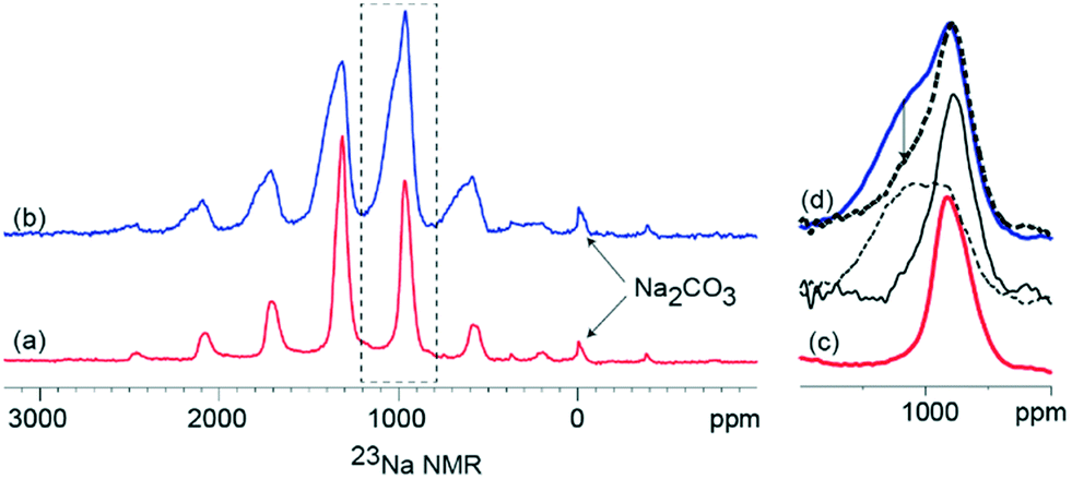 | ||
| Fig. 3 Solid state 23Na NMR at 30 kHz MAS of (a) Na0.7Mn0.8Mg0.2O2 (b) K-modified P2 Na0.7Mn0.8Mg0.2O2 acquired after 1 rotor period Hahn-echo. (c) and (d) are expansions of (a) and (b) respectively, to highlight the differences in the line shapes. Bold dashed line spectrum of (a) recorded after 4 rotor period Hahn echo. Narrow solid line and arrow dashed lines are the long T2 component and short T2 components of (b), obtained by a scaled difference between the short and long Hahn echo spectra of (b). | ||
XPS was used as another probe to compare K-modified and K-free P2 Na0.7Mn0.8Mg0.2O2 as prepared electrodes. The K 2p1 and K 2p3 spectral region (Fig. 4(a)) clearly shows the presence of K in the K modified P2 Na0.7Mn0.8Mg0.2O2 electrode and subtle differences are noted in the Na 1s spectral region (Fig. 4(b)) mirroring the subtle changes in the NMR data. Mn 2p3 and Mg 2p regions are shown in ESI† Fig. S4.
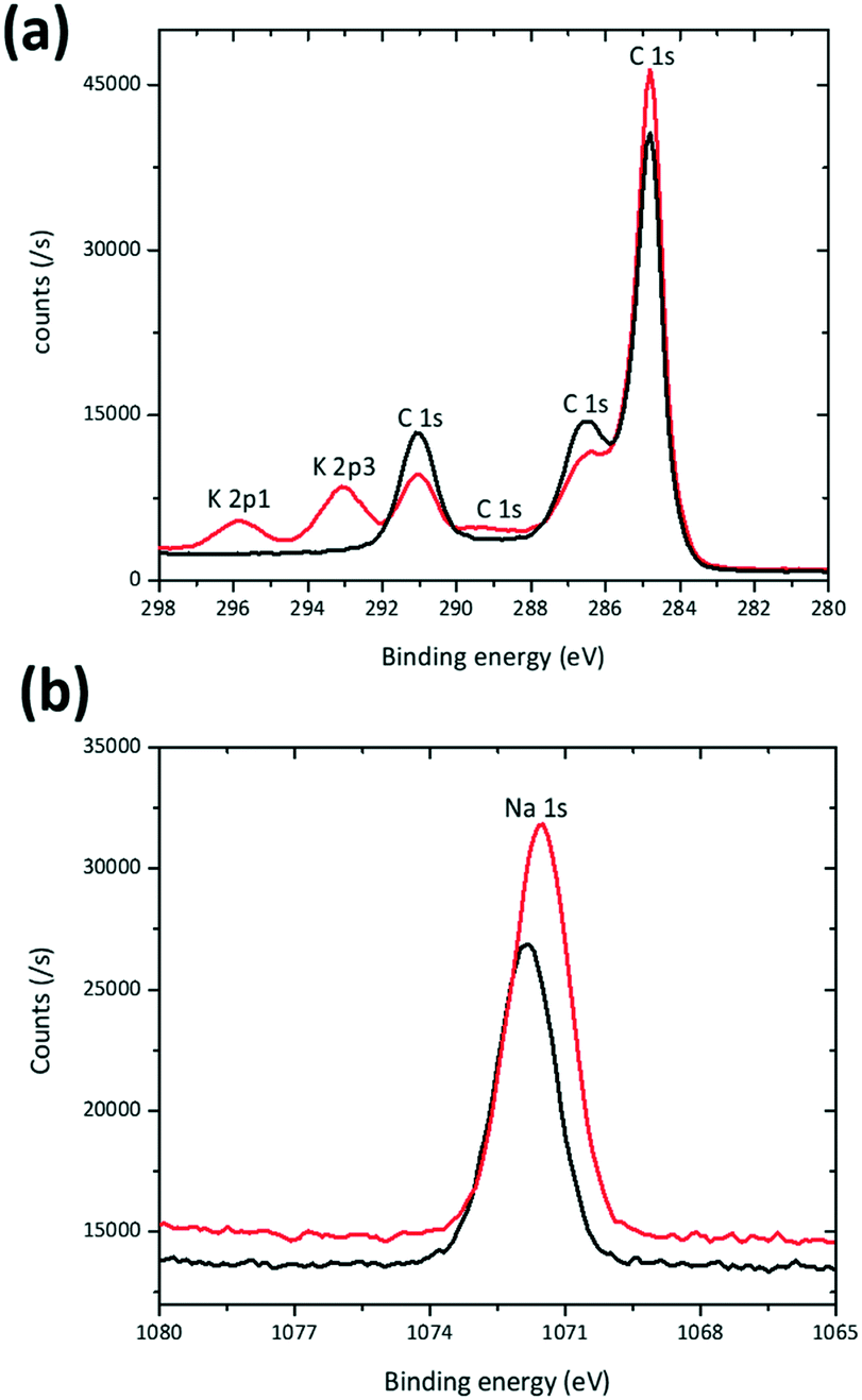 | ||
| Fig. 4 XPS spectra of the Na0.7Mn0.8Mg0.2O2 (black) and K modified Na0.7Mn0.8Mg0.2O2 (red) electrode in the (a) K 2p1, K 2p3, and C 1s and (b) Na 1s regions. | ||
The distribution of K on electrodes was examined using XANES K L-edge spectra, Fig. 5a. Data were collected in PEY and TFY modes for characterisation of the surface (sampling depth of ∼10 nm) and the bulk (sampling depth of ∼200 nm) of the electrode28 respectively. A comparison of the PEY and TFY signals of the fresh cathode of K-modified P2 Na0.7Mn0.8Mg0.2O2 shows K is predominantly on the surface, not in the bulk of the electrode. Comparatively, Fig. 5b and c show the PEY and TFY curves for Na and Mg, clearly illustrating a distribution both on the surface and bulk.
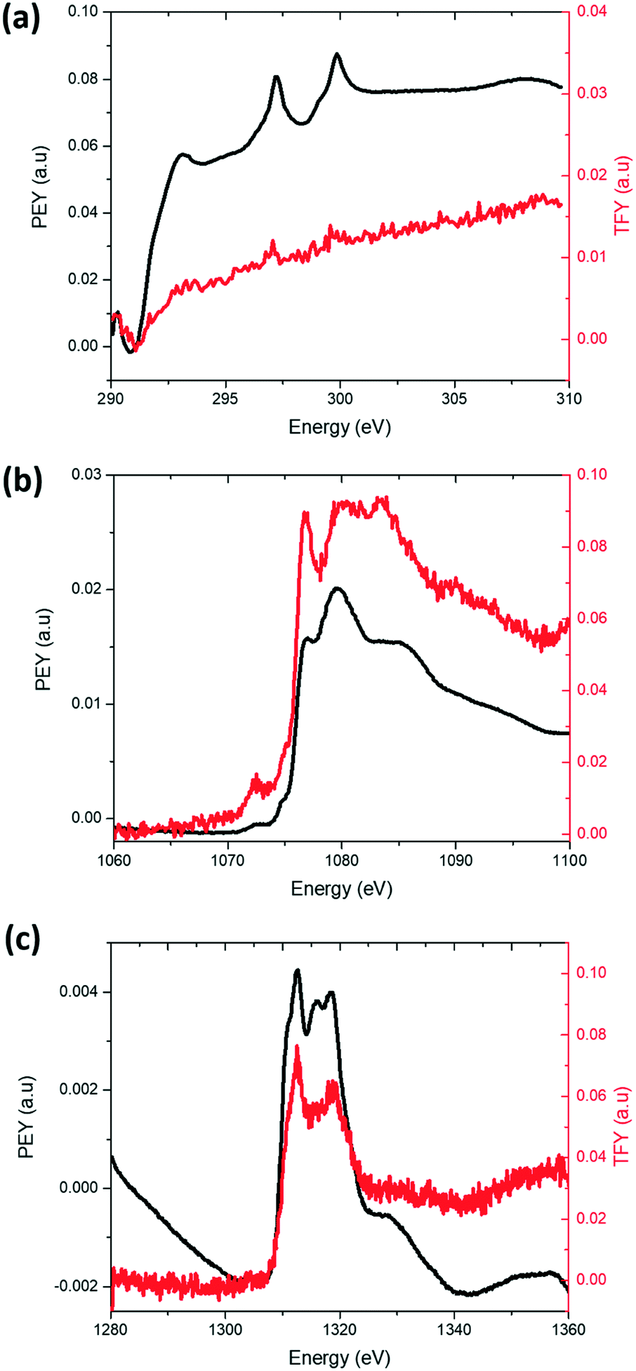 | ||
| Fig. 5 XANES (a) K L-edge (b) Na K-edge and (c) Mg K-edge profile of the K-modified P2 Na0.7Mn0.8Mg0.2O2 cathode. The black solid line denotes the signal collected in PEY mode corresponding a ∼10 nm sampling depth, and the red solid line denotes the signal collected in TFY mode corresponding to a ∼200 nm sampling depth. | ||
In summary, K is clearly present heterogeneously in the sample (Fig. 1) and does modify the local sodium environments (Fig. 3) of P2 Na0.7Mn0.8Mg0.2O2, however the nature or form of K is difficult to determine due to its small concentration and heterogeneous distribution (Fig. 1). There is no evidence of secondary K-containing phases in XRD data (Fig. 2a) which may indicate an amorphous or nanocrystalline phase. Further, the reaction is carbon-free and the temperatures used preclude significant CO2 interaction.
Electrochemical characterisation
Detailed electrochemical characterisation and comparison of the K-modified and K-free P2 Na0.7Mn0.8Mg0.2O2 are shown in Fig. S5 and S6.† The theoretical capacities are 277 mA h g−1 and 266 mA h g−1 for K-free and K-modified P2 Na0.7Mn0.8Mg0.2O2 respectively. Charge–discharge curves of K-modified P2 Na0.7Mn0.8Mg0.2O2 at different current rates and potential cut-offs are shown in Fig. 6. The potential profiles exhibit relatively smooth slopes. Upon de-sodiation during the 1st charge to 4.2 V at 15 mA g−1, a capacity of 25 mA h g−1 was observed, while upon sodiation during the 1st discharge to 1.5 V at 15 mA g−1, a capacity of 111 mA h g−1 was observed (Fig. 6a). The second charge/discharge capacity for the K-modified P2 Na0.7Mn0.8Mg0.2O2 was 115/111 mA h g−1, which reduced to 61/60 mA h g−1 after 100 cycles. The first charge capacity of the P2 type material is surprisingly low in this composition compared to the parent. A possible explanation of this low 1st charge capacity could be the electrode surface accumulation of K evidenced by XANES acting to limit capacity in the 1st charge. Nonetheless, maintaining the same applied current but reducing the potential window to 2–4 V (Fig. 6b), the 1st charge/discharge capacity of the K-modified P2 Na0.7Mn0.8Mg0.2O2 was 20/77 mA h g−1 and 2nd charge/discharge capacity was 80/75 mA h g−1 while the 100th cycle capacity was 63/62 mA h g−1. The rationale for smaller voltage windows are typically to avoid phase transitions at high and low potentials (where the sodium concentration in the cathode is low and high respectively) and this typically in electrochemical terms results in better capacity retention although the specific capacities are lower. The capacity retention from 2nd to 100th cycle between the 1.5–4.2 and 2–4 V cut off windows were 53% and 79% respectively (Fig. 6(c)). The charge–discharge curves of P2 Na0.7Mn0.8Mg0.2O2 and the comparison of capacity retention of K-modified P2 Na0.7Mn0.8Mg0.2O2 with P2 Na0.7Mn0.8Mg0.2O2 are shown in ESI† Fig. S5 and S6 respectively. The average operating voltage of K-modified P2 Na0.7Mn0.8Mg0.2O2 and P2 Na0.7Mn0.8Mg0.2O2 for first discharge between 1.5–4.2 V was 2.29 V and 2.49 V respectively. The energy density with respect to the active material mass of K-modified P2 Na0.7Mn0.8Mg0.2O2 and P2 Na0.7Mn0.8Mg0.2O2 were 254.19 W h kg−1 and 356.72 W h kg−1. | ||
| Fig. 6 Charge–discharge curves of K-modified P2 Na0.7Mn0.8Mg0.2O2 between (a) 1.5–4.2 V and (b) 2–4 V at a current density of 15 mA g−1. Black shows 1st, red 2nd, green 10th, blue 25th, pink 50th, dark cyan 75th and orange 100th cycle and (c) capacity versus cycle number between 1.5–4.2 V (brown square) and 2–4 V (violet square). | ||
A comparison of the cycling performance of K-modified P2 Na0.7Mn0.8Mg0.2O2 at different current densities (15 mA g−1, 30 mA g−1, 45 mA g−1, 60 mA g−1 and 90 mA g−1) is shown in Fig. 7 in the potential ranges of (a) 1.5–4.2 V and (b) 2–4 V. There is a noticeable decrease in the capacity with increased current rates and capacities of 70 mA h g−1 at 90 mA g−1 in 1.5–4.2 V and 56 mA h g−1 in 2.0–4.0 V are found. In both potential ranges, capacity is partially recovered when the applied current is reduced back to 15 mA g−1.
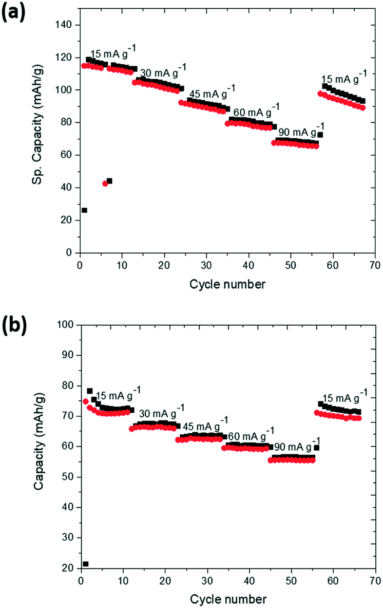 | ||
| Fig. 7 Rate capability of K-modified P2 Na0.7Mn0.8Mg0.2O2 between (a) 1.5–4.2 V and (b) 2–4 V. Black is charge, and red is discharge. | ||
To investigate whether K was removed from the electrode with cycling ICP-OES were performed on the separator at the 1st charged and 1st discharged states. Unfortunately, the data were not conclusive since the K concentrations were relatively low, see in ESI† Table S2.
In situ electrochemical-structural characterization
For the initial assessment of the K-modified P2 Na0.7Mn0.8Mg0.2O2 phase evolution during charge/discharge, selected 2θ ranges are plotted in Fig. 8. The cell used for the in situ XRD experiment yielded a capacity of 32 mA h g−1 during 1st charge, 118 mA h g−1 during 1st discharge and 132 mA h g−1 during 2nd charge, comparable to the capacity of conventional coin cells at the current rates employed. | ||
| Fig. 8 Selected 2θ regions of in situ synchrotron XRD data of K-modified P2 Na0.7Mn0.8Mg0.2O2 highlighting the evolution of the (a) (002) and (b) (100) reflections. The green shaded region shows multiple-phases, yellow represents two-phase regions and non-shaded regions indicates predominantly solid solution reactions. The potential profile is also included and (c) the evolution of the (002) reflection near the discharged state. | ||
The phase evolution of K-modified P2 Na0.7Mn0.8Mg0.2O2 during charge/discharge/charge is mostly solid solution with some two-phase and multiple-phase regions, as shown in Fig. 8. Within the solid solution regions, there is a constant change in the diffraction angle 2θ for the (002) reflection corresponding to the stacking axis. On charge, the (002) reflection (Fig. 8(a)) decreases in 2θ, and on discharge it increases; this corresponds to an increase and decrease of the distance between the layers respectively. The (100) reflection (Fig. 8b) shows opposite trends in 2θ compared to (002), which indicates an anisotropic evolution of the lattice parameters during sodiation/de-sodiation. Near the charged state, the (002) reflection appears to split into multiple reflections. These multiple reflections illustrate that multiple phases are present at the 1st charged and 2nd charged states (shown by green shaded region in Fig. 8a).
Looking closer at the discharged state, from 1st discharge at 1.8 V, 532 minutes to 2nd charge at 2 V, 700 minutes the reflections appear to decrease in intensity and broaden while changing in 2θ-value (black arrow, Fig. 8c). This may indicate the beginning of subtle two-phase reaction near the discharged state.
The Rietveld refined fit to the first in situ synchrotron XRD dataset of K-modified P2 Na0.7Mn0.8Mg0.2O2 is shown in Fig. 9a. Fig. 9b shows evidence of two features around the 002 reflection which may indicate at least two phases are present in the region near the charged state. The first in situ dataset (at t = 0 minutes), K-modified P2 Na0.7Mn0.8Mg0.2O2 adopts hexagonal P63/mmc symmetry with lattice parameters a = 2.8791(3) Å and c = 11.229(3) Å. Crystallographic details can be found in Table 3 and the fit is shown in Fig. 9a. Note that values for the parameters are slightly different to those obtained from the pure powder because our structural model represented here is of the material inside a battery, which is in constant contact with an electrolyte, and thus some Na exchange (Na loss/gain) may occur.21
 | ||
| Fig. 9 Rietveld refined fit of the P2 Na0.7Mn0.8Mg0.2O2 model to the (a) first and (b) charged state in situ XRD dataset where data are shown as red dots, the calculated Rietveld model as a black line through the data, and the difference between the data and the model as the blue line below the data and pink vertical markers are the reflection markers of P2 Na0.70Mn0.8Mg0.2O2. (c) Phase evolution of the K-modified P2 Na0.7Mn0.8Mg0.2O2 electrode during charge/discharge assuming a single-phase model with the a (black) and c (red) lattice parameters, volume (blue) and the potential profile. The green shading represent multiple-phase regions, yellow shading two-phase regions and non-shaded regions indicates predominantly solid solution reactions. | ||
| Atom | Wyckoff | X | Y | Z | SOF | Isotropic ADP (×100/Å) |
|---|---|---|---|---|---|---|
| ADP = atomic displacement parameter, SOF = site occupation factors. a Fixed. b Initially refined then fixed. c Constrained to be equal. Hexagonal P63/mmc symmetry with lattice parameters a = 2.8795(3) Å and c = 11.233(3) Å, χ2 = 1.31, wRp = 4.22%, 28 refinement parameters. | ||||||
| Mn | 2 | 0 | 0 | 0 | 0.8a | 20(1)c |
| Mg | 2 | 0 | 0 | 0 | 0.2a | 20(1)c |
| O | 4 | 0.3333 | 0.6667 | 0.127(2) | 1a | 17.0(7) |
| Naf | 2 | 0.3333 | 0.6667 | 0.75 | 0.32(2) | 17.5b |
| Nae | 2 | 0 | 0 | 0.25 | 0.379(8) | 8.13b |
Assuming a purely single-phase model, the evolution of the lattice parameters is shown in Fig. 9c, where the only refined parameters were lattice parameters and background. Note that the two phases present in the multiple phase region have very similar lattice parameters and thus are difficult to reliably deconvolute within the refinements. On the first charge, a lattice parameter decreases to 2.8667(3) Å and increases to 2.9371(6) Å on discharge while the c lattice parameter on charge increases to 11.2808(8) Å and decreases to 10.876(2) Å on discharge. The maximum change with the single P2 model assumption in volume is 1.321(1) Å3, where Δc is 0.4162(7) Å and Δa is 0.0704(3) Å. The volume appears to stabilise near the discharged state from 2 V, 364 minutes on 1st discharge to 2.3 V, 840 minutes on 2nd charge with an average value of 81.40 ± 0.02 Å3. This region also corresponds to an onset of the reduction in diffraction peak intensity.
These data were collected in situ every 28 minutes and the current rate applied to the in situ cell adjusted to ensure a full cycle is complete during the beamtime. The structural evolution measured is related to the electrochemical conditions used for such experiments. The smooth electrochemical curve follows the predominantly observed solid solution type behaviour. Lower current experiments closer to equilibrium conditions and high current experiments are likely to show different structural evolution as previously demonstrated for P2 Na0.67Mn0.8Mg0.2O2.21
The parent P2 Na0.7Mn0.8Mg0.2O2 has a higher overall capacity in comparison to the K-modified P2 Na0.7Mn0.8Mg0.2O2 which suggests that the heterogeneously distributed K is adverse for electrochemical performance. There are differences in the structural evolution of the electrode compared to the parent P2 Na0.67Mn0.8Mg0.2O2.29 In particular, there are no significant quantities of the P′2 Cmcm phase formed at the discharged state, although a loss of reflection intensity may be evidence for the initiation of such a phase transformation.
Conclusions
K-Modified P2 Na0.7Mn0.8Mg0.2O2 was synthesized by conventional solid-state reaction and used in sodium-ion batteries. SEM images illustrate that K-modified P2 Na0.7Mn0.8Mg0.2O2 is comprised of irregular plates while STEM-EDS mapping indicates that K resides heterogeneously in the sample while all other elements appear to be distributed evenly on the particles examined. Solid-state NMR illustrates that K perturbs the local Na environment of a proportion of Na sites within P2 Na0.7Mn0.8Mg0.2O2. XANES K L-edge spectra indicate that K is localised on the surface of the electrode rather than the bulk while Na and Mg K-edge spectra show Na and Mg are present on both the surface and bulk. Overall the structural evolution of the K-modified Na0.7Mn0.8Mg0.2O2 shows the combination of solid solution and multiple phase regions. This work illustrates the adverse influence that heterogeneously distributed K has on electrochemical performance of these electrodes. Interesting, the presence of K appears to have a significant influence on the local Na environments which are in turn influencing the electrochemical parameters.Conflicts of interest
There are no conflicts to declare.Acknowledgements
We would like to thank Lisa Djuandhi, Emily Cheung and Jennifer Stansby, PhD students in the Sharma group for conducting the XANES experiment. This work was financially supported by the Australian Research Council DECRA (DE160100237) and DP (DP170100269) programs. In situ XRD and XANES experiments were undertaken on the Powder Diffraction and soft X-ray spectroscopy beamlines respectively at the Australian Synchrotron, Victoria, Australia. This research used the facilities supported by AMMRF at the Electron Microscope Unit at UNSW.References
- H. Pan, Y.-S. Hu and L. Chen, Energy Environ. Sci., 2013, 6, 2338–2360 RSC.
- K. Kubota and S. Komaba, J. Electrochem. Soc., 2015, 162, A2538–A2550 CrossRef CAS.
- V. Palomares, P. Serras, I. Villaluenga, K. B. Hueso, J. Carretero-Gonzalez and T. Rojo, Energy Environ. Sci., 2012, 5, 5884–5901 RSC.
- V. Palomares, M. Casas-Cabanas, E. Castillo-Martinez, M. H. Han and T. Rojo, Energy Environ. Sci., 2013, 6, 2312–2337 RSC.
- J.-Y. Hwang, S.-T. Myung and Y.-K. Sun, Chem. Soc. Rev., 2017, 46, 3529–3614 RSC.
- H. Kim, H. Kim, Z. Ding, M. H. Lee, K. Lim, G. Yoon and K. Kang, Adv. Energy Mater., 2016, 6, 1600943 CrossRef.
- R. J. Clément, P. G. Bruce and C. P. Grey, J. Electrochem. Soc., 2015, 162, A2589–A2604 CrossRef.
- D. Buchholz, C. Vaalma, L. G. Chagas and S. Passerini, J. Power Sources, 2015, 282, 581–585 CrossRef CAS.
- J. Billaud, G. Singh, A. R. Armstrong, E. Gonzalo, V. Roddatis, M. Armand, T. Rojo and P. G. Bruce, Energy Environ. Sci., 2014, 7, 1387–1391 RSC.
- N. Yabuuchi, R. Hara, K. Kubota, J. Paulsen, S. Kumakura and S. Komaba, J. Mater. Chem. A, 2014, 2, 16851–16855 RSC.
- U. Maitra, R. A. House, J. W. Somerville, N. Tapia-Ruiz, J. G. Lozano, N. Guerrini, R. Hao, K. Luo, L. Jin, M. A. Pérez-Osorio, F. Massel, D. M. Pickup, S. Ramos, X. Lu, D. E. McNally, A. V. Chadwick, F. Giustino, T. Schmitt, L. C. Duda, M. R. Roberts and P. G. Bruce, Nat. Chem., 2018, 10, 288 CrossRef CAS PubMed.
- M. Sathiya, K. Ramesha, G. Rousse, D. Foix, D. Gonbeau, A. S. Prakash, M. L. Doublet, K. Hemalatha and J. M. Tarascon, Chem. Mater., 2013, 25, 1121–1131 CrossRef CAS.
- M. Keller, D. Buchholz and S. Passerini, Adv. Energy Mater., 2016, 6, 1501555 CrossRef PubMed.
- R. Shannon, Acta Crystallogr., Sect. A: Cryst. Phys., Diffr., Theor. Gen. Crystallogr., 1976, 32, 751–767 CrossRef.
- E. Talaie, V. Duffort, H. L. Smith, B. Fultz and L. F. Nazar, Energy Environ. Sci., 2015, 8, 2512–2523 RSC.
- S. C. Han, H. Lim, J. Jeong, D. Ahn, W. B. Park, K.-S. Sohn and M. Pyo, J. Power Sources, 2015, 277, 9–16 CrossRef CAS.
- Y. Hironaka, K. Kubota and S. Komaba, Chem. Commun., 2017, 53, 3693–3696 RSC.
- B. C. C. Cowie, A. Tadich and L. Thomsen, 10th International Conference on Radiation Instrumentation, AIP Conf. Proc., 2010, 1234, 307–310 CrossRef.
- P. Serras, V. Palomares, T. Rojo, H. E. Brand and N. Sharma, J. Mater. Chem. A, 2014, 2, 7766–7779 RSC.
- N. Sharma, P. Serras, V. Palomares, H. E. Brand, J. Alonso, P. Kubiak, M. L. Fdez-Gubieda and T. Rojo, Chem. Mater., 2014, 26, 3391–3402 CrossRef CAS.
- J. C. Pramudita, S. Schmid, T. Godfrey, T. Whittle, M. Alam, T. Hanley, H. E. Brand and N. Sharma, Phys. Chem. Chem. Phys., 2014, 16, 24178–24187 RSC.
- D. Sehrawat, J. Zhang, D. Y. W. Yu and N. Sharma, Small Methods, 2018, 0, 1800092 CrossRef.
- K. S. Wallwork, B. J. Kennedy and D. Wang, AIP Conf. Proc., 2007, 879, 879–882 CrossRef CAS.
- A. C. Larson and R. B. Von Dreele, Los Alamos Natl. Lab., [Rep.] LA, 1994, 86–748 Search PubMed.
- B. H. Toby, J. Appl. Crystallogr., 2001, 34, 210–213 CrossRef CAS.
- B. H. Toby and R. B. Von Dreele, J. Appl. Crystallogr., 2013, 46, 544–549 CrossRef CAS.
- K. A. Aldi, J. Cabana, P. J. Sideris and C. P. Grey, Am. Mineral., 2012, 97, 883–889 CrossRef CAS.
- A. Ruosi, C. Raisch, A. Verna, R. Werner, B. A. Davidson, J. Fujii, R. Kleiner and D. Koelle, Phys. Rev. B: Condens. Matter Mater. Phys., 2014, 90, 125120 CrossRef.
- N. Sharma, N. Tapia-Ruiz, G. Singh, A. R. Armstrong, J. C. Pramudita, H. E. A. Brand, J. Billaud, P. G. Bruce and T. Rojo, Chem. Mater., 2015, 27, 6976–6986 CrossRef CAS.
Footnote |
| † Electronic supplementary information (ESI) available: Structural and electrochemical characterization of parent P2 Na0.7Mn0.8Mg0.2O2. See DOI: 10.1039/c8ce01532e |
| This journal is © The Royal Society of Chemistry 2019 |