DOI:
10.1039/C9CC04238E
(Communication)
Chem. Commun., 2019,
55, 9092-9095
Locally pH controlled and directed growth of supramolecular gel microshapes using electrocatalytic nanoparticles†
Received
2nd June 2019
, Accepted 2nd July 2019
First published on 2nd July 2019
Abstract
Controlled localization of platinum nanoparticles (Pt NPs) at a solid support assisted by a polarized liquid–liquid interface is reported. Electrocatalytic water oxidation resulted in local pH modulation followed by the directed self-assembly of a dibenzoyl-L-cystine hydrogelator forming a structured hydrogel retaining the shape of the Pt NP deposit.
Supramolecular hydrogels have been reported to find applications in the fields of cell culture1 and drug delivery systems2 among many others. The ability to exert spatial control over the formation of these materials is therefore of high value. Directed self-assembly of supramolecular hydrogelators composed of low molecular weight gelators has seen rapid progress in recent years. With the ability to control supramolecular gel formation using pH or catalysts,3,4 researchers have shown that spatial structuring at the microscale is possible by using light,5 catalytic surfaces,6 electrochemistry,7,8 reaction–diffusion9 and very recently, charged polymer brushes.10 However, such approaches need the aid of masks to create patterns, secondary supporting networks to act as reservoirs for gelator precursors or micro-contact printing to template micropatterns. Hence, new techniques allowing localized control over hydrogel formation and structuring can pave the way for novel soft material fabrication and patterning. Electrochemical approaches for hydrogel study and formation established so far, although limited to only a few reports, have shown promise due to their ease of use, reversibility and multiplexing ability.7,11,12 In this work, we take this approach to the next level by demonstrating localized control over hydrogel formation. This is achieved with the help of a polarized liquid–liquid interface to deposit Pt NPs on a conducting substrate of fluorine doped tin oxide (FTO) electrodes. The polarized liquid–liquid interface also known as the interface between two immiscible electrolyte solutions (ITIES) is soft, renewable, free from defects and allows the electrochemical study of interfacial ions or electron transfer processes. The liaison between ITIES and functional materials is a relatively new and unexplored topic.13 The ion or electron transfer reactions or the self-assembly process can lead to interfacial region modification with a number of functional materials (e.g. molecular sieves, liquid mirrors, and metal catalysts).14–16 When the ITIES is in contact with the conducting support a so-called three phase junction is formed. At the junction where the three phases meet, the interfacial ion transfer coupled to a redox reaction can result in very precise electrochemical deposition (e.g. the formation of Au NPs or silica).17–19 In this work, we have employed this strategy to obtain patterned (rings, stripes and spots) hydrogels by controlled formation of Pt NPs that will act as catalysts for the electrochemical splitting of water to produce a proton gradient. Controlled and localized Pt NP deposition at the micro-meter scale is facilitated by the ITIES (micro-capillary supported liquid–liquid interface) or by a three phase junction system. The proton gradient thus produced causes the self-assembly of the hydrogelator dibenzoyl-L-cystine (DBC). For simplicity, we have chosen an off-the shelf gelator as a model molecule. We believe that this technology platform provides a solid foundation for future electrochemically assisted deposition and writing of supramolecular hydrogels.
First, we focus on the demonstrating that an electrocatalytic effect of Pt NPs results in hydrogel formation. The FTO electrode placed in an electrochemical cell (experimental details are available in Section S2.1 of the ESI†) was contacted via a circular opening to a 1 mM aqueous solution of K2PtCl6 and the Pt NPs were deposited via chronoamperometry for a period of 10 min. The potential applied (E = −1.5 V vs. Ag/AgCl) was sufficient to reduce PtCl62− to metallic Pt according to reactions (1) and (2):
| | |
PtIVCl62− + 2e− → PtIICl42− + 2Cl−
| (1) |
| | |
PtIICl42− + 2e− → Pt0 + 4Cl−
| (2) |
Fig. 1B shows the FTO electrode decorated with a dark circle containing Pt NPs. Investigation by scanning electron microscopy (SEM) revealed that the deposited Pt NPs are well dispersed over the support and that their sizes ranged from 100 to 200 nm (see
Fig. 1C and Fig. S5B, ESI
†). Additional characterization by X-ray photoelectron spectroscopy (XPS) (see Fig. S4, ESI
†) confirmed the presence of metallic Pt. The cyclic voltammograms recorded in aqueous 250 mM NaNO
3 before (the red line in
Fig. 1A) and after deposition of Pt NPs (the black line in
Fig. 1A) show a clear electrocatalytic effect on water oxidation. For the latter, the anodic current recorded at 1.5 V was 115 times higher compared to a non-modified FTO electrode having the same planar surface area. Two additional cathodic peaks recorded around 0.32 V and −0.26 V are typical fingerprints of oxygen reduction and H
+ adsorption to the Pt electrodes, respectively.
20 The Pt NPs deposited on the FTO substrate were then used for the electrochemically assisted hydrogel deposition experiments. An aqueous 40 mM solution of the sodium salt of the DBC gelator with additional 250 mM NaNO
3 as the supporting electrolyte was used. Linear sweep voltammetry was carried out at a scan rate of 10 mV s
−1 with the forward polarization towards more anodic potential (typically the experiment was stopped between 2.5 and 3.0 V) and polarized light optical microscopy (POM) was used
in situ to record the changes at the surface of the FTO electrode. It is known that DBC gel fibers orient themselves along the diffusion gradient of the protons,
21 and hence, their presence can be monitored and confirmed by POM.
Fig. 1D displays the POM image of the FTO electrode modified with Pt NPs. The boundary between the Pt NP modified and non-modified region is observed by microscopy as is indicated by the red line (inset in
Fig. 1D). The application of a linearly increasing anodic potential triggers the water oxidation reaction:
| | |
2H2O − 4e− → 4H+ + O2
| (3) |
As the local concentration of H
+ increases, we can observe the emergence of the DBC hydrogel (see
Fig. 1E together with the inset). From the image recorded we conclude that: (i) the hydrogel is built from DBC fibres and structured by the linear diffusion of protons from the support and (ii) in some of the regions of the support the emergence of the so-called Maltese cross patterns indicates the radial orientation of the fibres, which in turn may suggest the presence of the isolated Pt NP clusters or preferential electrocatalytic sites (behaving as the individual nano-electrodes).
22 The presence of DBC fibres was further confirmed by cryo-transmission electron microscopy investigations on electrochemically modified copper grids (see Fig. S9 with the corresponding description, ESI
†) decorated with Pt NPs which clearly showed the formation of fibers from the Pt NP surface. In order to control the local deposition of Pt NPs we combined the PtCl
62− (initially present in the organic phase) transfer reactions across the electrified liquid–liquid interface with its reduction occurring at the FTO. First, we synthesized the organic phase soluble salt – PtCl
6(BTPPA)
2via a simple metathesis reaction (see Section S1.3 in the ESI
† for details). We then studied its electrochemical behaviour at the ITIES in a typical four electrode configuration as described in Section S2.2 of the ESI.
† We expected to find the proof of principle that there is a transfer of PtCl
62−.
Fig. 2A shows the ion transfer voltammogram recorded at the interface between the aqueous 10 mM NaCl and 10 mM BTPPATPBCl (the hydrophobic salt) dissolved in 1,2-dichloroethane (the organic phase). The observed potential window is limited by Na
aq↔org+ and Cl
aq↔org− transfer on the more and less positive potential sites, respectively. Addition of PtCl
6(BTPPA)
2 at μM concentration to the organic phase results in the emergence of two peaks with
E1/2 = 0.25 V within the available potential window (
Fig. 2B). The positive peak is attributed to PtCl
6,org→aq2−. The ratio of the integrated positive and negative signals approaching unity indicates the reversibility of the process.
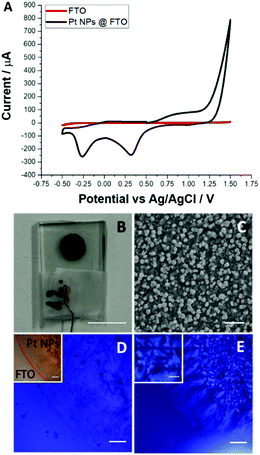 |
| | Fig. 1 (A) Cyclic voltammograms recorded in an aqueous solution of 250 mM NaNO3 before (red) and after (black) Pt NP deposition at −1.5 V via a single step chronoamperometry for 10 min. (B) The photo of the corresponding modified electrode. (C) A SEM image of the area containing Pt NPs. (D) The optical microscopy image of the Pt NPs deposited (before hydrogel formation) on FTO under cross-polarized conditions (inset shows an image under normal light conditions with the boundary of Pt NPs indicated). (E) The optical microscopy image recorded under cross-polarization; after hydrogel formation the same FTO surface Section is shown in (D) and (E). The inset shows the Maltese cross-hair patterns zoomed in further. Scale bars are: (B) 5 mm; (C) 1 μm; (D), (D)-inset and (E) 200 μm; and (E)-inset 100 μm. | |
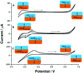 |
| | Fig. 2 Ion transfer voltammograms recorded at the liquid–liquid interface formed between (A) 10 mM NaCl (aq)//10 mM BTPPATPBCl (org); (B) 10 mM NaCl (aq)//x μM (x = 58; 116; 174 and 232 μM) BTPPA2PtCl6 in 10 mM BTPPATPBCl (org) and (C) 10 mM NaCl (aq)//5 mM BTPPA2PtCl6 (org). The scan rate was 10 mV s−1; the dashed arrow indicates the direction of the forward scan. | |
Fig. 2C shows the recordings when the organic phase contained only 5 mM PtCl6(BTPPA)2 (the concentration used in further experiments) and shows the potential window, which is now limited at the negative potential side by the PtCl6,aq↔org2−. The concept of a three phase junction modification was mainly studied by the group of Opallo, where Au NPs or silica materials were electrochemically generated in a defined locus.17–19 To the best of our knowledge, this is the first time that the three phase junction is decorated with Pt NPs. The modification follows a few mutually related ion and electron transfer reactions which are depicted together in the electrical scheme in Fig. 3. First a reductive potential is applied to the FTO electrode and the PtCl62− present in the organic phase undergoes reduction to metallic Pt (according to reactions (1) and (2)) at the three phase junction. For an applied potential (E = −1.5 V) its reduction in the organic phase is unlikely due to the very high resistance of the circuit (the high resistivity of the organic phase and the position of the reference electrode), and is therefore excluded. The Cl− formed within the junction or on the organic side of the ITIES will partition to the aqueous phase due to its high intrinsic hydrophilicity:
| |
ClITIES![[thin space (1/6-em)]](https://www.rsc.org/images/entities/char_2009.gif) ororg− → Claq− ororg− → Claq−
| (4) |
In order to maintain the charge balance the anion (still soluble in the aqueous phase and significantly less hydrophilic than Cl
−) from the aqueous phase should transfer to the organic phase. This was provided with unidirectional BF
4− transfer:
As confirmed by the control experiment, in the absence of a charge balancing ion, the
reactions (1), (2) and (4) will not occur and no deposit will be found (data not shown). Although PtCl
62− is more hydrophobic than
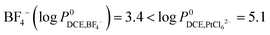
– as mentioned in Section 3 of the ESI
†23 we found that for experimental concentrations of [BF
4,aq−] = 100 mM and [PtCl
62−] = 5 mM the latter was partitioned from the organic to the aqueous phase (a clear colour change of the aqueous phase was observed over time):
| | |
PtCl6,org2− → PtCl6,aq2−
| (6) |
Whenever PtCl
62− diffuses towards the cathodically polarized FTO electrode the
reactions (1) and (2) occur. To demonstrate control over the directed self-assembly of hydrogelators, different configurations of the FTO substrate and the liquid–liquid interface were made (see
Fig. 4, row A). The detailed experimental information can be found in Sections S2.2–S2.5 of the ESI.
† Three designs were implemented to control the localization of Pt NPs: (i) design where the conductive substrate was dipped into the organic phase (a solution of 5 mM BTPPA
2PtCl
6 in 1,2-DCE) and came into contact with the aqueous phase on top (
Fig. 4(A1)); (ii) design where a micro-droplet of the organic phase containing 5 mM BTPPA
2PtCl
6 is cast on top of the FTO substrate (
Fig. 4(A2)); and (iii) design where a micro-capillary filled with the organic phase is positioned close to the FTO substrate (
Fig. 4(A3)).
 |
| | Fig. 3 A schematic representation of the three phase junction system. Organic phase is 1,2-dichloroethane. For details refer to the text. | |
 |
| | Fig. 4 Three configurations used for localized Pt NP deposition (1A) scheme of a three phase junction for stripe deposition; (1B) scheme of a three phase junction for ring deposition and (1C) scheme of a micro-capillary supporting ITIES for micro-spot deposition. Panel (B) corresponds to optical microscopy images (insets show the energy dispersive X-ray spectroscopy mapping of Pt). Panels (C) and (D) represent polarization microscopy images before and after hydrogel deposition, respectively. The columns 1, 2 and 3 show the results for stripes, rings and micro-spots respectively. Scale bars are: 100 μm (left to right, (B1)–(B3), (C1)–(C3), (D1)–(D2)) and 50 μm (D3) respectively. | |
In the first two designs, the formation of Pt NPs occurs at the three-phase junction while in the third design, this junction is absent and the Pt NPs are produced by the transfer of PtCl62− from the organic to aqueous phase followed by its reduction at the FTO substrate. The micro-patterns reach in Pt NPs result from the designs in the form of stripes (ca. 175 μm), rings (ca. 1.5 mm diameter, 225 μm thick rim) and spots (ca. 60 μm diameter) respectively (Fig. 4 panel B). It was also observed that the width of the pattern was dependent on the deposition time (data not shown). The presence of the Pt NPs was confirmed in all three cases via SEM (Fig. S8, ESI†) in combination with EDS elemental mapping (inset Fig. 4 row B).
The formation of hydrogels from these patterns was carried out using linear sweep voltammetry (see Section S2.6 of ESI†). It can be seen (Fig. 4 image 1D, 2D and 3D) that there is birefringence under cross-polarization indicating the formation of oriented fibres. The time evolution of the hydrogel pattern together with a linear sweep voltammogram is shown in Fig. S10 (ESI†). From the nature of the polarization pattern, it can be concluded that the DBC fibres are oriented radially outward based on the diffusion of the protons (towards a bulk phase) produced at the interface of the Pt NP catalyst and the aqueous gelator environment. The produced hydrogels retain their shape of the base micro-pattern while being broader. Especially interesting is the hydrogel deposition achieved over a micro-spot as shown in Fig. 4 panel 3. As the region filled with Pt NPs has a micrometre size, it resembles a single microdisc electrode, in which the mass transport (to and from the electrode) will be governed by a hemispherical diffusion. The very prominent and clear Maltese cross patterns indicate that the formed hydrogel has radial orientation and probably a dome-like shape. This observation is in line with similar hemispherical shapes of silica,24–26 metallic27 or polymeric28 deposits obtained over an array of nano- and micro-electrodes.
In summary, electrochemically controlled Pt NP deposition proposed in this work was used to produce sophisticated hydrogel patterns by combining them with supramolecular hydrogelators. A polarized liquid–liquid interface was used to control the localization of Pt NPs, thereby creating new opportunities to design complicated and unusual gel patterns in a very straightforward manner. The electrocatalytic effect of Pt NPs on water oxidation allowed a local pH change which triggered the growth of a structured hydrogel directly from the support. Electrochemical patterning of hydrogels using the technique developed in this work can be used as a platform to create functional soft matter down to a micro- or nano-metre scale. As such, it opens up new directions for gel processing with potential applications in cell culturing, drug delivery, tissue engineering, sensing, diagnostics etc. Such an approach may be used to produce nano-patterned electro responsive surfaces capable of templating hydrogels and other functional soft materials.
The authors thank the NanoNextNL (a Dutch consortium of 130 companies, universities, knowledge institutes and university medical centres) Program 7A for funding. The authors thank Bart Boshuizen for his help with XPS characterization.
Conflicts of interest
There are no conflicts to declare.
Notes and references
- V. Jayawarna, M. Ali, T. A. Jowitt, A. F. Miller, A. Saiani, J. E. Gough and R. V. Ulijn, Adv. Mater., 2006, 18, 611–614 CrossRef CAS.
- A. Friggeri, B. L. Feringa and J. van Esch, J. Controlled Release, 2004, 97, 241–248 CrossRef CAS.
- J. Boekhoven, J. M. Poolman, C. Maity, F. Li, L. van der Mee, C. B. Minkenberg, E. Mendes, J. H. van Esch and R. Eelkema, Nat. Chem., 2013, 5, 433–437 CrossRef CAS.
- F. Trausel, F. Versluis, C. Maity, J. M. Poolman, M. Lovrak, J. H. Van Esch and R. Eelkema, Acc. Chem. Res., 2016, 49, 1440–1447 CrossRef CAS.
- C. Maity, W. E. Hendriksen, J. H. van Esch and R. Eelkema, Angew. Chem., Int. Ed., 2015, 127, 1012–1015 CrossRef.
- A. G. L. Olive, N. H. Abdullah, I. Ziemecka, E. Mendes, R. Eelkema and J. H. van Esch, Angew. Chem., Int. Ed., 2014, 53, 4132–4136 CrossRef CAS.
- Y. Liu, E. Kim, R. V. Ulijn, W. E. Bentley and G. F. Payne, Adv. Funct. Mater., 2011, 21, 1575–1580 CrossRef CAS.
- J. Raeburn, B. Alston, J. Kroeger, T. O. McDonald, J. R. Howse, P. J. Cameron and D. J. Adams, Mater. Horiz., 2014, 1, 241–246 RSC.
- M. Lovrak, W. E. J. Hendriksen, C. Maity, S. Mytnyk, V. van Steijn, R. Eelkema and J. H. van Esch, Nat. Commun., 2017, 8, 15317 CrossRef CAS.
- Y. Wang, S. Oldenhof, F. Versluis, M. Shah, K. Zhang, V. van Steijn, X. Guo, R. Eelkema and J. H. van Esch, Small, 2019, 1804154 CrossRef.
- E. R. Cross and D. J. Adams, Soft Matter, 2019, 15, 1522–1528 RSC.
- M. Zelzer and R. V. Ulijn, Chem. Soc. Rev., 2010, 39, 3351–3357 RSC.
- L. Poltorak, A. Gamero-Quijano, G. Herzog and A. Walcarius, Appl. Mater. Today, 2017, 9, 533–550 CrossRef.
- L. Poltorak, K. Morakchi, G. Herzog and A. Walcarius, Electrochim. Acta, 2015, 179, 9–15 CrossRef CAS.
- E. Smirnov, P. Peljo, M. D. Scanlon, F. Gumy and H. H. Girault, Nanoscale, 2016, 8, 7723–7737 RSC.
- T. J. Stockmann, L. Angel, V. Brasiliense, C. Combellas and F. Kanoufi, Angew. Chem., Int. Ed., 2017, 56, 13493–13497 CrossRef CAS.
- J. Niedziolka and M. Opallo, Electrochem. Commun., 2008, 10, 1445–1447 CrossRef CAS.
- I. Kaminska, M. Jonsson-niedziolka, A. Kaminska, M. Pisarek, R. Ho, M. Opallo and J. Niedziolka-jonsson, J. Phys. Chem. C, 2012, 116, 22476–22485 CrossRef CAS.
- I. Kaminska, J. Niedziolka-jonsson, A. Roguska and M. Opallo, Electrochem. Commun., 2010, 12, 1742–1745 CrossRef CAS.
- D. Huang, B. Zhang, J. Bai, Y. Zhang, G. Wittstock, M. Wang and Y. Shen, Electrochim. Acta, 2014, 130, 97–103 CrossRef CAS.
- I. Ziemecka, G. J. M. Koper, A. G. L. Olive and J. H. van Esch, Soft Matter, 2013, 9, 1556 RSC.
- D. W. M. Arrigan, Analyst, 2004, 129, 1157–1165 RSC.
- M. Suzuki, S. Kihara, K. Maeda, K. Ogura and M. Matsui, J. Electroanal. Chem., 1990, 292, 231–244 CrossRef CAS.
- Y. Liu, A. Holzinger, P. Knittel, L. Poltorak, A. Gamero-Quijano, W. D. A. Rickard, A. Walcarius, G. Herzog, C. Kranz and D. W. M. Arrigan, Anal. Chem., 2016, 88, 6689–6695 CrossRef CAS.
- L. Poltorak, G. Herzog and A. Walcarius, Langmuir, 2014, 30, 11453–11463 CrossRef CAS.
- A. Holzinger, G. Neusser, B. J. J. Austen, A. Gamero-Quijano, G. Herzog, D. W. M. Arrigan, A. Ziegler, P. Walther and C. Kranz, Faraday Discuss., 2018, 210, 113–130 RSC.
- C. Zhu, G. Meng, Q. Huang, Z. Li, Z. Huang, M. Wang and J. Yuan, J. Mater. Chem., 2012, 22, 2271–2278 RSC.
- Y. Sakurai, S. Okuda, H. Nishiguchi, N. Nagayama and M. Yokoyama, J. Mater. Chem., 2003, 13, 1862–1864 RSC.
Footnotes |
| † Electronic supplementary information (ESI) available: Methods and materials, protocols for organic salt preparation, details pertaining to electrochemical set-ups, water–1,2-dichloroethane partition coefficient calculations, and additional XPS, SEM and TEM results. See DOI: 10.1039/c9cc04238e |
| ‡ These authors contributed equally. |
|
| This journal is © The Royal Society of Chemistry 2019 |
Click here to see how this site uses Cookies. View our privacy policy here. 
 Open Access Article
 This Open Access Article is licensed under a
  a,
Lukasz Poltorak
a,
Lukasz Poltorak

 – as mentioned in Section 3 of the ESI†23 we found that for experimental concentrations of [BF4,aq−] = 100 mM and [PtCl62−] = 5 mM the latter was partitioned from the organic to the aqueous phase (a clear colour change of the aqueous phase was observed over time):
