 Open Access Article
Tailoring patches on particles: a modified microcontact printing routine using polymer-functionalised stamps†
Marcel
Sperling‡
ab,
Martin
Reifarth‡
ab,
Richard
Grobe
ab and
Alexander
Böker
 *ab
*ab
aFraunhofer Institute for Applied Polymer Research IAP, D-14476 Potsdam-Golm, Germany. E-mail: alexander.boeker@iap.fraunhofer.de
bChair of Polymer Materials and Polymer Technologies, University Potsdam, D-14476 Potsdam-Golm, Germany
First published on 6th August 2019
Abstract
Herein, we report a modified microcontact printing (μCP) routine suitable to introduce particle patches of a low molecular weight ink (LMWI) on porous SiO2 microparticles. Thereby, patch precision could be significantly improved by utilising stamps which have been surface-functionalised with grafted polymers. This improvement was evaluated by a profound software-assisted statistical analysis.
The fabrication of anisotropic structures – which comprise nanoscale objects with non-spherical (e.g. rod- or prism-like) particle geometry as well as spherical particles with anisotropically functionalised surfaces – has gained increasing research interest in colloidal science. The latter, which are referred to as patchy particles (including Janus-type materials as a sub-class), possess defined surface domains with distinct individual chemical characteristics.1,2 Their asymmetry and the concomitant directionality renders them materials of considerable interest with respect to their potential to undergo self-organization3–5 or to perform automotion in solution.6
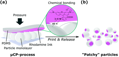
There exist different strategies to introduce patchy functionalities on particles, such as vapour deposition of metals,7–9 seed-mediated nucleation and growth synthesis10–12 among many others. Being a robust and experimentally feasible technique suitable for upscaling,13 microcontact printing (μCP) can be considered as an alternative powerful technique to fabricate anisotropic particles.14–16 This technique is based on ink transfer from a stamp material onto a substrate surface exclusively at the area of contact (Fig. 1).
All subsequent applications of patchy particles demand a defined functionality from the patch. In this context, either the patch material itself should possess an activity (e.g. a catalytic activity6,17) or offer binding sites for the attachment of more functional molecules in following modification steps.15 In particular, the locally selective addition of surface functional groups to the particles would thereby be attractive, since it exclusively alters local surface properties rather than their topology. Literature examples show, that surface-active compounds can be used for this purpose, which alter the particle surface charge, hydrophobicity or wettability at the patched areas and, therefore, render the resulting patchy particles anisotropic.18–20
An alternative, very elegant approach is to employ functional precursor molecules to form surface anchor groups for subsequent modification reactions. Such a modification may possibly be a (living) polymerization via a grafting from-approach, which can lead to well-defined polymer shell architectures21 and, hence, to a sophisticated patch functionality.22
This perspective along with the aforementioned advantages of μCP motivated us to utilise low molecular-weight compounds as inks (LMWI). LMWI printing, however, suffers from poor patch definition as a result of uncontrolled ink-flow on the particle surface, particularly if porous substrates are employed. We, therefore, developed a novel and versatile approach, which relies on a strong reduction of uncontrolled ink-flow without the necessity of a protective matrix shielding the particles’ bodies.22 Accordingly, tailoring of particle patches in terms of diameter was performed with much greater precision compared to the conventional μCP routine using smooth and flat stamps.
As a benchmark particle system, we selected silicon dioxide (SiO2) microparticles (ρsolid = 1.8 g mL−1) as well as rhodamine B isothiocyanate (RITC) as LMWI. As a consequence of the (meso-) porous nature of the SiO2-particles, generating LMWI patches with a high precision was expected to be a demanding task due to enhanced capillary forces inducing ink flow on the particle surface. This is also reflected in the fact that the preparation of LMWI patches on particles with a certain porosity, well in contrast to particles with smooth surfaces, e.g. polymeric19,23 or metallic20 ones, has hitherto been neglected in recent literature. Therefore, it was our aim to demonstrate the potential of μCP for the functionalisation of SiO2 as a particularly challenging material. In this context, it was important to us to enable a covalent attachment of the ink material to the particle surface, which is necessary to support any potential chemical post-modification.
As an appropriate model LMWI that can be covalently bound to a particle surface and which can function as a label simultaneously, rhodamine B isothiocyanate (RITC) was selected, since it supports a straightforward characterization of the resulting particle patches by means of fluorescence microscopy (FM). Thereby, its isothiocyanate functional group allows for the covalent attachment of the dye to, e.g. an amino-functionalised SiO2 particle surface. As stamp base-material, we employed polydimethylsiloxane (PDMS).
In a typical μCP routine, an inked stamp is placed onto a monolayer of amino-modified particles with a defined pressure (Fig. 1). Since ink-transfer to the particle surface exclusively occurs at the area of contact between particle and stamp, investigations on the morphology of the resulting patches is directly related to the quality of the μCP process. Accordingly, for characterization via FM, the particles are oriented such that the printed patches face the microscope's objective, i.e. the particles are observed from printing site (schematic representation and explanation of experimental conditions in Fig. S1, ESI†). In consequence, this setup represents the planar projection of the particle patches, which allows for patch diameter analysis of a statistically considerable number of particles.
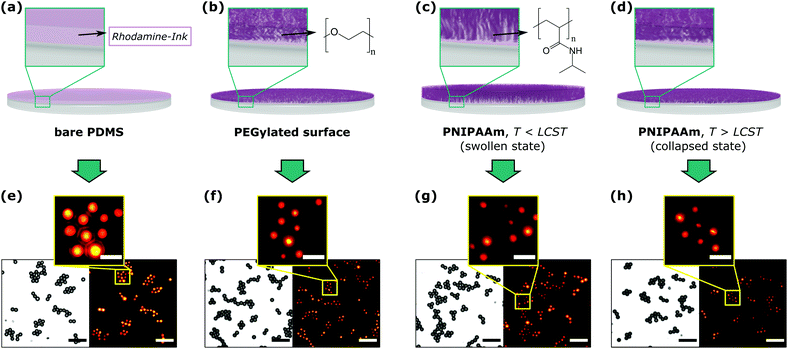
Fig. 2 exemplifies the results of our printing experiments. In the top row, the individual printing experiments are depicted schematically. The bottom row shows transmission light (TL) images of the imprinted particles next to their corresponding fluorescence (FL) images. The yellow boxes represent a zoom-in view of the FL-images for better visualisation. In a first experiment, we utilized bare PDMS as stamp material (Fig. 2a), which was subjected to an aqueous RITC solution as ink for a certain amount of time, followed by its withdrawal and gentle drying using a soft air stream. TL- and FL-images of the imprinted particles (Fig. 2e) reveal that the fluorescent spots possess smaller dimensions compared to the particle shapes, i.e. that this process produces patchy particles. Fig. 2e, however, also reveals that the patches possess rather large diameters and less defined edges resulting from LMWI diffusive ink-flow on the particle surface. This observation would not be expected for high molecular-weight, e.g. polymeric, inks,14,15,24 which possess a much higher viscosity and are, thus, less prone to ink flow.
Inspired by the suitability of polymers as efficient inks, we envisioned the use of a polymeric auxiliary to inhibit, in a similar manner, the diffusion of LMWI compounds by enhancing the local viscosity (Fig. 2b–d). This would consequently increase the control over the printing process, while, at best, the auxiliary is immobilised on the stamp, in order to prevent its transfer to the particle surface during μCP.
Providentially, PDMS opens the possibility for a manifold surface chemistry via its surface activation using plasma treatment. This results in the formation of a silicon dioxide layer, which is suitable for further functionalisation, with, for instance, alkoxy silanes.
In a first instance, we modified the activated stamps with methoxy-initiated poly(ethylene glycol)triethoxysilane (mPEG), a commercially available building block, in a sense of a grafting to-approach (Fig. 2b). The printing results as shown in Fig. 2f reveal the formation of patches, whereby a first visual comparison of these results with Fig. 2e suggests that printing with mPEG-modified stamps yields patches with decreased dimensions. In another experiment, we utilized the commercially available poly(N-isopropylamino acrylamide)triethoxysilane (PNIPAAm) as a more functional surface modification. This polymer shows a thermo-responsive hydrophilicity with a lower critical solution temperature (LCST) of 32 °C. Inking these stamps at room temperature, i.e. in their hydrophilic state, resulted in the formation of well-defined particle patches after printing (Fig. 2c and g). At 45 °C, i.e. in their hydrophobic state, patches with an even higher precision were observed, which adds temperature as another optional process parameter to the μCP process for future experiments (Fig. 2d and h).
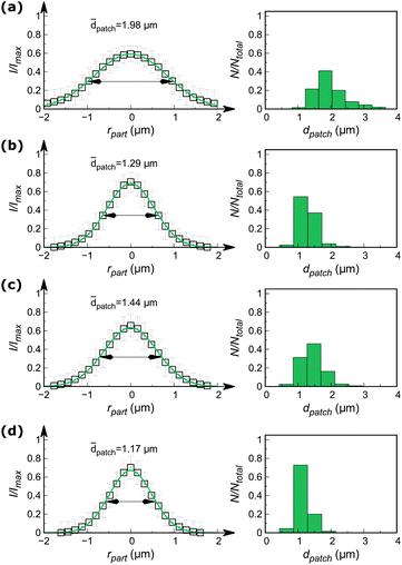
A visual comparison of the acquired images (Fig. 2e–h) already enables a rough estimation of the printing quality. In order to obtain resilient data allowing for further profound and objective description of the printing process, however, a quantitative discussion of these results becomes indispensable. For this purpose, we developed a custom-made automated image processing algorithm utilizing Fiji/ImageJ25,26 and the programming language Python,27 which is described in more detail in the ESI.† In summary, this algorithm (Fig. S2, ESI†) generates an overall patch intensity profile, by extracting numerous radial patch signals (typically >1000 signals), which are normalised and averaged for each printing experiment, whereby their characterisation is performed by fitting with a Gaussian profile (Fig. S3, ESI†). Fig. 3 (left column) shows the corresponding radial profile plots, wherein the full widths at half maximum (FWHM) of the individual fit functions were selected as a measure of patch diameters (summarised in Table S2, ESI†). In parallel the average particle diameter was determined at 3.7 μm by analysis of the TL-images.
The radial intensity profiles shown in Fig. 3 along with the extracted patch diameters (Table S2, ESI†) essentially confirm the above discussed visual observations of the results in Fig. 2. Fig. 3 clearly shows that printing with pristine PDMS indeed yields patchy particles with defined patches, however, with rather huge average patch diameters (![[d with combining macron]](https://www.rsc.org/images/entities/i_char_0064_0304.gif) patch = 1.98 μm). A significant decrease of
patch = 1.98 μm). A significant decrease of ![[d with combining macron]](https://www.rsc.org/images/entities/i_char_0064_0304.gif) patch was obtained for PEGylated stamps yielding
patch was obtained for PEGylated stamps yielding ![[d with combining macron]](https://www.rsc.org/images/entities/i_char_0064_0304.gif) patch = 1.29 μm, which is a result of a locally enhanced viscosity of the LMWI at the stamp surface due to the presence of the polymer. PNIPAAm-functionalised stamps similarly provide precise patches when printing was performed with inking at room temperature (
patch = 1.29 μm, which is a result of a locally enhanced viscosity of the LMWI at the stamp surface due to the presence of the polymer. PNIPAAm-functionalised stamps similarly provide precise patches when printing was performed with inking at room temperature (![[d with combining macron]](https://www.rsc.org/images/entities/i_char_0064_0304.gif) patch = 1.44 μm). Nevertheless, the patches appeared slightly larger as for PEGylated stamps (1.44 vs. 1.29 μm). This fact, however, needs to be put into context in sight of the different chain lengths of the two polymers (2.5 kDa PNIPAAm vs. 5 kDa PEG according to mass spectrometry data, see Fig. S4, ESI†). Printing experiments performed with PNIPAAm-functionalised stamps with inking at 45 °C yielded particle patches with a significantly improved precision compared to printing at RT (1.44 vs. 1.17 μm). This can be explained by the microscopic structure of the PNIPAAm framework at this temperature. At 45 °C, the hydrophilicity of the PNIPAAm drastically decreases and the polymer chains collapse in aqueous ink solution. As a consequence, we expect the RITC molecules to be entrapped in the collapsed polymer framework (Fig. 2d). Due to the therefore drastically increased viscosity28 the LMWI substance experiences, its transfer to the particle surface becomes more precise. Based on the automated image processing, the right column in Fig. 3 represents the distribution of patch diameters of the individual particles. From these graphs, it becomes obvious that with smaller patch sizes, the absolute patch precision increases. Note that supported by the individual FWHM values, the standard deviation of particle patches stays almost constant (approx. ± 25%). Further discussion about the fluorescence microscopy performance, particularly in sight of the supported resolution of the employed setup (approx. 430 nm in lateral direction) is provided in the ESI† of this article.
patch = 1.44 μm). Nevertheless, the patches appeared slightly larger as for PEGylated stamps (1.44 vs. 1.29 μm). This fact, however, needs to be put into context in sight of the different chain lengths of the two polymers (2.5 kDa PNIPAAm vs. 5 kDa PEG according to mass spectrometry data, see Fig. S4, ESI†). Printing experiments performed with PNIPAAm-functionalised stamps with inking at 45 °C yielded particle patches with a significantly improved precision compared to printing at RT (1.44 vs. 1.17 μm). This can be explained by the microscopic structure of the PNIPAAm framework at this temperature. At 45 °C, the hydrophilicity of the PNIPAAm drastically decreases and the polymer chains collapse in aqueous ink solution. As a consequence, we expect the RITC molecules to be entrapped in the collapsed polymer framework (Fig. 2d). Due to the therefore drastically increased viscosity28 the LMWI substance experiences, its transfer to the particle surface becomes more precise. Based on the automated image processing, the right column in Fig. 3 represents the distribution of patch diameters of the individual particles. From these graphs, it becomes obvious that with smaller patch sizes, the absolute patch precision increases. Note that supported by the individual FWHM values, the standard deviation of particle patches stays almost constant (approx. ± 25%). Further discussion about the fluorescence microscopy performance, particularly in sight of the supported resolution of the employed setup (approx. 430 nm in lateral direction) is provided in the ESI† of this article.
It has to be annotated that the data presented in Fig. 2 and 3 was acquired immediately after printing and, thus, is strongly associated with the μCP process quality. For further application of the functionalities introduced as patches on the particles, however, it becomes important to ensure the covalent attachment of the LMWI, which we achieved by an extended stamp holding time.
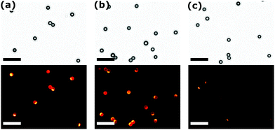
To demonstrate a covalent immobilisation, we exposed the stamp with the collected particles to ethanol as a suitable solvent for RITC and subjected them to ultrasonication. Fig. 4 shows detached and re-dispersed particles as TL- and FL-images. The distinct patches clearly prove that we indeed obtained a strong chemical binding of the LMWI material with an anisotropic distribution on the particle surface. Further results for printing and annealing at different experimental conditions, are discussed in Fig. S5 and summarised in Table S3 (ESI†).
In conclusion, we used RITC as functional, highly mobile molecule to manufacture patchy SiO2 particles via a modified μCP process. For this purpose, we used PDMS stamps and were able to show that their surface modification with polymeric compounds drastically improves the quality of the resulting patchy particles. We attribute this behaviour to an increase of the local viscosity within the ink-layer on the stamp surface during the printing process. We want to point out here that the introduced approach is not limited to fluorescent dyes only but can be extended to a large portfolio of further, highly functional water-soluble molecules. In this context, investigations of the influence of different printing parameters, e.g. holding time, printing pressure, printing temperature, as well as the influence of the chain length of the employed polymers on the printing performance or the extension of this approach to other binding chemistries represent interesting future challenges.
The authors acknowledge the European Research Council (ERC) for funding in the framework of the research project Replicoll (Project 648365).
Conflicts of interest
There are no conflicts to declare.Notes and references
- A. B. Pawar and I. Kretzschmar, Macromol. Rapid Commun., 2010, 31, 150–168 CrossRef CAS PubMed.
- S. Jiang, Q. Chen, M. Tripathy, E. Luijten, K. S. Schweizer and S. Granick, Adv. Mater., 2010, 22, 1060–1071 CrossRef CAS PubMed.
- K. J. Lee, J. Yoon and J. Lahann, Curr. Opin. Colloid Interface Sci., 2011, 16, 195–202 CrossRef CAS.
- A. Walther and A. H. E. Müller, Chem. Rev., 2013, 113, 5194–5261 CrossRef CAS PubMed.
- G.-R. Yi, D. J. Pine and S. Sacanna, J. Phys.: Condens. Matter, 2013, 25, 193101 CrossRef PubMed.
- D. P. Singh, W. E. Uspal, M. N. Popescu, L. G. Wilson and P. Fischer, Adv. Funct. Mater., 2018, 28, 1706660 CrossRef.
- A. B. Pawar and I. Kretzschmar, Langmuir, 2009, 25, 9057–9063 CrossRef CAS PubMed.
- A. B. Pawar and I. Kretzschmar, Langmuir, 2008, 24, 355–358 CrossRef CAS PubMed.
- R. J. Archer, A. I. Campbell and S. J. Ebbens, Soft Matter, 2015, 11, 6872–6880 RSC.
- T. Teranishi, M. Saruyama and M. Kanehara, Nanoscale, 2009, 1, 225–228 RSC.
- S. Watanabe, Y. Asahi, H. Omura, K. Mae and M. T. Miyahara, Adv. Powder Technol., 2016, 27, 2335–2341 CrossRef CAS.
- M. T. Perez Cardenas, C. Kong, J. He, S. Litvin, M. L. Meyerson and Z. Nie, ACS Nano, 2018, 12, 1107–1119 CrossRef CAS PubMed.
- T. Kaufmann and B. J. Ravoo, Polym. Chem., 2010, 1, 371–387 RSC.
- F. N. Mehr, D. Grigoriev, N. Puretskiy and A. Böker, Soft Matter, 2019, 15, 2430–2438 RSC.
- M. Zimmermann, D. John, D. Grigoriev, N. Puretskiy and A. Böker, Soft Matter, 2018, 14, 2301–2309 RSC.
- T. Kaufmann, M. T. Gokmen, C. Wendeln, M. Schneiders, S. Rinnen, H. F. Arlinghaus, S. A. F. Bon, F. E. Du Prez and B. J. Ravoo, Adv. Mater., 2011, 23, 79–83 CrossRef CAS PubMed.
- M. Sperling, H.-J. Kim, O. D. Velev and M. Gradzielski, Adv. Mater. Interfaces, 2016, 3, 1600095 CrossRef.
- O. Cayre, V. N. Paunov and O. D. Velev, J. Mater. Chem., 2003, 13, 2445–2450 RSC.
- O. Cayre, V. N. Paunov and O. D. Velev, Chem. Commun., 2003, 2296–2297 RSC.
- M. Rycenga, J. M. McLellan and Y. Xia, Adv. Mater., 2008, 20, 2416–2420 CrossRef CAS.
- M. Sokolowski, C. Bartsch, V. J. Spiering, S. Prévost, M.-S. Appavou, R. Schweins and M. Gradzielski, Macromolecules, 2018, 51, 6936–6948 CrossRef CAS.
- X. Fan, J. Yang, X. J. Loh and Z. Li, Macromol. Rapid Commun., 2019, 40, 1800203 CrossRef PubMed.
- P. Seidel and B. J. Ravoo, Macromol. Chem. Phys., 2016, 217, 1467–1472 CrossRef CAS.
- D. John, M. Zimmermann and A. Böker, Soft Matter, 2018, 14, 3057–3062 RSC.
- C. T. Rueden, J. Schindelin, M. C. Hiner, B. E. DeZonia, A. E. Walter, E. T. Arena and K. W. Eliceiri, BMC Bioinf., 2017, 18, 529 CrossRef PubMed.
- ImageJ: v. 1.52h w. Java 1.8.0_172 (64-bit) available at http://imagej.nih.gov/ij.
- Python 3.7.0 (64-bit) available at https://www.python.org, utilised during this study.
- M. V. Badiger and B. A. Wolf, Macromol. Chem. Phys., 2003, 204, 600–606 CrossRef CAS.
Footnotes |
| † Electronic supplementary information (ESI) available. See DOI: 10.1039/c9cc03903a |
| ‡ Both authors contributed equally to this work. |
| This journal is © The Royal Society of Chemistry 2019 |


