
 Open Access Article
 This Open Access Article is licensed under a Creative Commons Attribution-Non Commercial 3.0 Unported Licence
Butterfly proboscis-inspired tight rolling tapered soft actuators†
Jeroen A. H. P.
Sol
 a,
Akhil R.
Peeketi
b,
Nihit
Vyas
b,
Albertus P. H. J.
Schenning
ac,
Ratna K.
Annabattula
*b and
Michael G.
Debije
*a
a,
Akhil R.
Peeketi
b,
Nihit
Vyas
b,
Albertus P. H. J.
Schenning
ac,
Ratna K.
Annabattula
*b and
Michael G.
Debije
*a
aLaboratory of Stimuli-Responsive Functional Materials and Devices (SFD), Department of Chemical Engineering and Chemistry, Eindhoven University of Technology (TU/e), 5600 MB Eindhoven, The Netherlands. E-mail: m.g.debije@tue.nl
bStimuli-Responsive Systems Laboratory, Department of Mechanical Engineering, Indian Institute of Technology Madras (IITM), 600036 Chennai, India. E-mail: ratna@iitm.ac.in
cInstitute for Complex Molecular Systems (ICMS), Eindhoven University of Technology (TU/e), 5600 MB Eindhoven, The Netherlands
First published on 15th January 2019
Abstract
Liquid crystalline networks have been fashioned into thin films with tapered thicknesses, revealing the possibility of rolling up extremely tightly when triggered thermally or with light. Compared to the often limited bending shown previously in liquid crystal network actuators, these tapered films curl up several hundreds of degrees. Finite element results of simulated functionally graded thin films with tapered thicknesses corroborate well with experimental work.
The world of robotics is at a point of revolution—soft robots are poised to challenge for supremacy. In particular, in the fields of sustainable energy harvesting,1 personal comfort2 and biomedical engineering,3 these remotely-addressable yet compliant materials are making great strides towards becoming the constituents of choice for many smart devices to come. For soft robotics researchers, the natural world is a great source of inspiration.4–8 Nature provides insights into many of the solutions to engineering problems facing soft robotics today: microrobots based on bacteria9 and electrospun water strider legs10 are two examples of using natural blueprints to generate novel man-made devices.
One of the prime candidate materials for bio-inspired soft robots is liquid crystal networks (LCNs), which are densely crosslinked polymers built up of reactive self-assembling monomers (“reactive mesogens”).11,12 The significance of LCNs in these developments is largely based on their anisotropic thermomechanical behaviour—upon disordering, LCNs shrink along the molecular director n, while they expand perpendicular to n.13 LCNs have been used to create biomimetic soft actuators: caterpillar-like inching robots,6 Venus flytrap-inspired grippers,5 high-power seedpod actuators,7 or, inspired by the locomotion of micro-organisms, “microrobots”.14,15
Remarkably, all LCN-based actuators reported to date feature a uniform film thickness. Recently, a tapered paper–polyester bilayer was reported in which the tapered structure showed neat rolling and could be used to grapple objects.16 However, in this case, the polyester acted as a shape memory material, meaning that autonomous actuation can only be performed once—in contrast to actuators based on LCNs, which are known to exhibit reversible motion.13
Previously shown splay-LCNs of constant film thickness typically bend up to a full rotation at elevated temperatures.13 In this work, LCNs are made with a thickness taper along the length of the film, similar to the proboscis of butterflies, their feeding organ (see Fig. 1a for a comparison).17,18 At rest, it is coiled up under their head, taking up minimal space. In action, it can extend to the body length of the butterfly and is used to retrieve nectar from plants or nutrients from rotting fruits, depending on the species of butterfly.19 Our proboscis-inspired tapered actuators show tight bending behaviour unique in splay-LCNs, with up to 3½ rotations upon heating or exposure to light. This rolling is fully reversible to reveal a nearly straight polymer strip at room temperature. Finite element modelling (FEM) results correspond well with experimental results. This allows for reversing the roles in the future, where the finite element model can be harnessed to anticipate the response of yet unexplored LC alignments and film geometries. Eventually, this could find use in designing LCN actuators that perform complex functions in larger soft robotic assemblies, or possibly as stand-alone devices in mixing systems for microfluidics.
 | ||
| Fig. 1 (a) (Left) Head of a Vanessa cardui butterfly featuring its proboscis (p) in the resting position. Photograph reproduced from Krenn19 with permission from Annual Reviews Inc. (Right) A tightly rolled tapered LCN film as described in this paper. (b) Schematic of the tapered actuator film concept; upon temperature increase or by irradiating with 455 nm light, the splay LCN rolls into a proboscis-like shape. When the light source is removed or the temperature is decreased, the sample unrolls. (c) Schematic showing the shape of a tapered LCN, depicting the molecular alignment n and other film characteristics such as the aspect ratio l/w and thicknesses di and do. Inset: Cross-section of a high-thickness splay-aligned LCN, featuring the molecular director (white arrows) as a function of film depth. (d) Reactive mesogens 1–3 and photo-initiator 4 used to fabricate the liquid crystalline network actuator. | ||
Tapered-thickness, splay-aligned LCN thin films are obtained by filling alignment cells with a liquid crystal mixture consisting of equal weight fractions of monoacrylate 1 and diacrylate crosslinker 2 (see Fig. 1d for structures, more experimental details in the ESI†). Photo-activated actuation is achieved through the incorporation of azobenzene dye 3, which covalently bonds to the LCN during photo-polymerisation. Photo-initiation of the free radical polymerisation is accomplished by 4. The phase behaviour of the mixture was studied by differential scanning calorimetry (DSC) and polarised optical microscopy (POM). These results indicate an isotropic to nematic transition at 77 °C (TN–I) when cooling, see Fig. S2 (ESI†) for details.
Splay-aligned LC cells were made by sticking together glass with homeotropic and rubbed planar polyimide alignment layers facing each other. Spacer glue (10 μm) and double-sided tape (50 μm) were used to provide an LC alignment cell with a tapered cell gap. These cells were filled with the LC mixture at 90 °C, above TN–I. After filling, the temperature was lowered to 55 °C, whereupon the LCs self-assembled into a nematic mesophase. After photo-initiated co-polymerisation to lock in the monomer's alignment, a thermal post-curing ensured maximum conversion of the acrylate groups (see Fig. S3, ESI,† for FT-IR data on C![[double bond, length as m-dash]](https://www.rsc.org/images/entities/char_e001.gif) C conversion). DSC reveals that the phase transition peak at TN–I has disappeared after polymerisation, as expected (see Fig. S2, ESI†). Cells were opened using a razor blade, revealing a thin film stuck to the glass coated with planar-aligned polyimide. Surface profilometry determined that film thicknesses were close to the spacer diameters chosen during cell manufacture. Furthermore, the thickness gradient between the thin and thick sides was linear. A polarised optical micrograph verified that the uniaxial nematic alignment was fixed during polymerisation, and dynamic mechanical analysis (DMA) revealed that the LCN has a broad glass transition range with the peak of tan(δ) at around 65 °C (Tg, see Fig. S4, ESI†). Scanning electron micrographs confirm that even at film thicknesses exceeding 100 μm, splay alignment is retained (see Fig. 1c). The estimated ratios of penetration depth between homeotropic- and planar-aligned mesogens through the depth of the film depend on the film thickness (see Fig. S5, ESI†).
C conversion). DSC reveals that the phase transition peak at TN–I has disappeared after polymerisation, as expected (see Fig. S2, ESI†). Cells were opened using a razor blade, revealing a thin film stuck to the glass coated with planar-aligned polyimide. Surface profilometry determined that film thicknesses were close to the spacer diameters chosen during cell manufacture. Furthermore, the thickness gradient between the thin and thick sides was linear. A polarised optical micrograph verified that the uniaxial nematic alignment was fixed during polymerisation, and dynamic mechanical analysis (DMA) revealed that the LCN has a broad glass transition range with the peak of tan(δ) at around 65 °C (Tg, see Fig. S4, ESI†). Scanning electron micrographs confirm that even at film thicknesses exceeding 100 μm, splay alignment is retained (see Fig. 1c). The estimated ratios of penetration depth between homeotropic- and planar-aligned mesogens through the depth of the film depend on the film thickness (see Fig. S5, ESI†).
Films were cut from the LCN as a strip with a Δd = (do − di) = 20 μm, davg = 25 μm, l/w = 4 and the thickness taper Δd in the same direction as the nematic director n (see Fig. 1c for a schematic image detailing these parameters). Upon removal of this film from the glass substrate, a free-standing film is obtained that shows no to little pre-bend, in which case the film slightly bends with the homeotropic side inward. This can be explained by the lower polymerisation temperature, which pre-empts the build-up of large thermal strains during polymerisation, and the thermal annealing, which also alleviates thermal stresses.20
The free-standing films were actuated in an oven with a window, through which photographs were recorded at set intervals. A digital temperature sensor recorded the temperature inside the oven at the same intervals. As the temperature was increased to 100 °C, the film rolled up tightly, with a curvature of several hundreds of degrees. This is best visualised in a series of photographs, as in Fig. 2 (see the ESI,† Video S1, for a time-lapse video).
 | ||
| Fig. 2 Comparison of experimental thermomechanical bending results (top) with finite element method results (bottom) for a tapered splay-aligned LCN film at different temperatures. Coloured regions in the finite element results correspond to the increasing value of curvature (1/rC) from blue to red. | ||
This behaviour can be explained with Timoshenko's model for bimetallic strips in mind, which correlates film thickness with the radius of curvature (rC) for a given differential thermal strain.21 In splay-aligned films with planar anchoring on one face of the film and homeotropic on the other, curling is observed typically up to a full rotation at elevated temperatures.13 Later, the use of (reactive) azobenzene-containing dopants allowed for the LCN to be addressed and actuated with light.1,5,6,22–28 Compared to this earlier work the tapered films show an increasingly smaller rC over their length, allowing them to effectively roll into themselves.
In order to better understand the bending behaviour of these tapered thickness LCNs, finite element simulations were performed. As described in more detail in the ESI,† the tapered geometry along the length of the film is discretised using four-noded shell elements with composite sectional properties for the finite element model. The properties of the elastic moduli and the thermal expansion as a function of temperature were measured and used as input for the model (see Fig. S4 and S6, ESI†). The finite element model incorporates the variation in the LC alignment direction through the depth of the film, thus making it a functionally graded system. The film is modelled as a three-layered system, in which each layer represents an area of the film with homeotropic, planar or intermediate (45° tilt) alignments. The relative thickness of the layers is programmed according to the depths found with scanning electron microscopy (SEM), as seen in Fig. S5 (ESI†). A video of the simulated functionally graded layer (ESI,† Video S2) shows that upon temperature increase tight rolling takes place.
There is a good correspondence between the predicted shapes and those achieved in practice (see Fig. 2), although the model somewhat overpredicts the bending behaviour of the film above 65 °C, the glass transition temperature. When plotting the inverse of the measured rC (Fig. 3, extended data in Fig. S7, ESI†), juxtaposed with the finite element result for rC, the same trend is seen even more clearly. We postulate that this is a result of a few factors. Firstly, the elastic moduli (E′ and E′′) of the material diminish strongly above Tg, decreasing at least an order of magnitude. However, as predicted by the model, the main driver for rolling is the ratio between the elastic modulus parallel (E11) and perpendicular (E22,33) to n. From DMA results (Fig. S4, ESI†) it is seen that the ratio between these moduli is not significantly influenced by the glass transition. In contrast, self-contact by the film might lead to friction that hampers tighter rolling. This is especially relevant as the material has its Tg around 65 °C, above which it is soft, which could promote surface adhesion. We postulate that above Tg a combination of this surface adhesion phenomenon with the lower absolute values of the elastic moduli is responsible for the overprediction by the model.
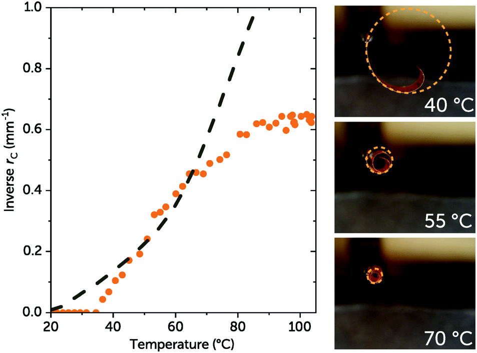 | ||
| Fig. 3 Plot showing measured rC for the LCN film from Fig. 2 at different temperatures (orange circles). The dashed grey line is composed of rC values from finite element analysis. Photographs on the right side detail the measurement method for rC. | ||
So far, modelling results have pointed out that the number of rotations made during thermal actuation depends mainly on the difference between thermal expansion coefficients (Δα) parallel and perpendicular to n (see Fig. S6, ESI,† for data on thermal strain).
To study the light response of the azobenzene-based LC material (compound 3, “disperse red 1 acrylate”), the film was irradiated with blue light (λ = 455 nm), activating the trans–cis isomerisation. This photoactivated reaction releases heat,1 thereby inducing thermomechanical bending. As demonstrated in Fig. S8b and c (ESI†), illumination from a single direction results in significant self-shading that prevents the film from bending fully into a rolled conformation. Turning on both light sources at once (Fig. 4) allows for otherwise shaded azobenzene molecules to be addressed, resulting in the formation of the anticipated tight curl. After turning off the light source, the film swiftly unbends, but a “post-bend” remains (ESI,† Video S3). We propose that this is due to vitrification during the backward motion, as actuation of the film occurs around the material's Tg.
 | ||
| Fig. 4 Tapered splay-aligned film irradiated with 455 nm light: (a) no illumination and (b) illumination from left and underneath at a total intensity of about 620 mW cm−2. | ||
In summary, we have generated a series of LCN films from liquid crystalline networks that boast a tapered geometry, with one side of the film thinner than the other. Actuation triggered by heat or light results in a smooth transition from fully extended to extremely tightly rolled morphologies, which are completely reversible and reproducible. Generation of actuators using tapered LCN films could allow more dramatic and consistent motions, allowing their application over a much broader range of devices to come. Our successful predictive model allows a wide exploration of potential actuation mechanisms to identify promising candidates to be produced experimentally.
The authors would like to express their gratitude towards Simon J. A. Houben (TU/e) for recording SEM pictures, and Marina Pilz da Cunha (TU/e) and Rob C. P. Verpaalen (TU/e) for results interpretation, discussion and DMA measurements. This research received funding from the Netherlands Organisation for Scientific Research (NWO) in the framework of the Innovation Fund Chemistry and from the Dutch Ministry of Economic Affairs in the framework of the PPP allowance.
Conflicts of interest
There are no conflicts to declare.Notes and references
- A. H. Gelebart, D. J. Mulder, M. Varga, A. Konya, G. Vantomme, E. W. Meijer, R. L. B. Selinger and D. J. Broer, Nature, 2017, 546, 632 CrossRef CAS PubMed.
- F. L. L. Visschers, M. Hendrikx, Y. Zhan and D. Liu, Soft Matter, 2018, 14, 4898 RSC.
- M. Cianchetti, C. Laschi, A. Menciassi and P. Dario, Nat. Rev. Mater., 2018, 3, 143 CrossRef.
- C. L. van Oosten, C. W. M. Bastiaansen and D. J. Broer, Nat. Mater., 2009, 8, 677 CrossRef CAS PubMed.
- O. M. Wani, H. Zeng and A. Priimagi, Nat. Commun., 2017, 8, 15546 CrossRef CAS PubMed.
- H. Zeng, O. M. Wani, P. Wasylczyk and A. Priimagi, Macromol. Rapid Commun., 2018, 39, 1700224 CrossRef PubMed.
- S. J. Aßhoff, F. Lancia, S. Iamsaard, B. Matt, T. Kudernac, S. P. Fletcher and N. Katsonis, Angew. Chem., Int. Ed., 2017, 56, 3261 ( Angew. Chem. , 2017 , 129 , 3309 ) CrossRef PubMed.
- T. J. Wallin, J. Pikul and R. F. Shepherd, Nat. Rev. Mater., 2018, 3, 84 CrossRef.
- S. Palagi and P. Fischer, Nat. Rev. Mater., 2018, 3, 113 CrossRef CAS.
- F. Bai, J. Wu, G. Gong and L. Guo, ACS Appl. Mater. Interfaces, 2014, 6, 16237 CrossRef CAS PubMed.
- H. Zeng, P. Wasylczyk, D. S. Wiersma and A. Priimagi, Adv. Mater., 2018, 30, 1703554 CrossRef PubMed.
- M. Lahikainen, H. Zeng and A. Priimagi, Nat. Commun., 2018, 9, 4148 CrossRef PubMed.
- G. N. Mol, K. D. Harris, C. W. M. Bastiaansen and D. J. Broer, Adv. Funct. Mater., 2005, 15, 1155 CrossRef CAS.
- H. Zeng, P. Wasylczyk, C. Parmeggiani, D. Martella, M. Burresi and D. S. Wiersma, Adv. Mater., 2015, 27, 3883 CrossRef CAS PubMed.
- D. S. Wiersma, S. Nocentini, C. Parmeggiani, D. Martella and D. Nuzhdin, in Optical Trapping and Optical Micromanipulation XIV, ed. K. Dholakia and G. C. Spalding, SPIE, 2017, p. 99 Search PubMed.
- W. Wang, C. Li, M. Cho and S.-H. Ahn, ACS Appl. Mater. Interfaces, 2018, 10, 10419 CrossRef CAS PubMed.
- H. W. Krenn and N. Mühlberger, Zool. Anz., 2002, 241, 369 CrossRef.
- H. W. Krenn and N. P. Kristensen, Eur. J. Entomol., 2004, 101, 565 CrossRef.
- H. W. Krenn, Annu. Rev. Entomol., 2010, 55, 307 CrossRef CAS PubMed.
- R. C. P. Verpaalen, M. G. Debije, C. W. M. Bastiaansen, H. Halilović, T. A. P. Engels and A. P. H. J. Schenning, J. Mater. Chem. A, 2018, 6, 17724 RSC.
- S. Timoshenko, J. Opt. Soc. Am., 1925, 11, 233 CrossRef CAS.
- T. J. White, J. Polym. Sci., Part B: Polym. Phys., 2018, 56, 695 CrossRef CAS.
- M. Yamada, M. Kondo, J. Mamiya, Y. Yu, M. Kinoshita, C. J. Barrett and T. Ikeda, Angew. Chem., Int. Ed., 2008, 47, 4986 ( Angew. Chem. , 2008 , 120 , 5064 ) CrossRef CAS PubMed.
- M. Hendrikx, B. Sırma, A. P. H. J. Schenning, D. Liu and D. J. Broer, Adv. Mater. Interfaces, 2018, 5, 1800810 CrossRef.
- H. P. C. van Kuringen, Z. J. W. A. Leijten, A. H. Gelebart, D. J. Mulder, G. Portale, D. J. Broer and A. P. H. J. Schenning, Macromolecules, 2015, 48, 4073 CrossRef CAS.
- A. H. Gelebart, M. K. McBride, A. P. H. J. Schenning, C. N. Bowman and D. J. Broer, Adv. Funct. Mater., 2016, 26, 5322 CrossRef CAS.
- T. J. White, R. L. Bricker, L. V. Natarajan, N. V. Tabiryan, L. Green, Q. Li and T. J. Bunning, Adv. Funct. Mater., 2009, 19, 3484 CrossRef CAS.
- J. Lv, Y. Liu, J. Wei, E. Chen, L. Qin and Y. Yu, Nature, 2016, 537, 179 CrossRef CAS PubMed.
Footnote |
| † Electronic supplementary information (ESI) available. See DOI: 10.1039/c8cc09915d |
| This journal is © The Royal Society of Chemistry 2019 |