 Open Access Article
Formation of unexpectedly active Ni–Fe oxygen evolution electrocatalysts by physically mixing Ni and Fe oxyhydroxides†
Mikaela
Görlin
 *abc,
Petko
Chernev
a,
Paul
Paciok
d,
Cheuk-Wai
Tai
 e,
Jorge
Ferreira de Araújo
b,
Tobias
Reier
b,
Marc
Heggen
 d,
Rafal
Dunin-Borkowski
 d,
Peter
Strasser
 b and
Holger
Dau
 a
a
aDepartment of Physics, Free University of Berlin, 14195 Berlin, Germany
bThe Electrochemical Energy, Catalysis, and Materials Science Laboratory, Department of Chemistry, Technical University of Berlin, 10623 Berlin, Germany
cDepartment of Physics, AlbaNova University Centre, Stockholm University, SE-10691 Stockholm, Sweden. E-mail: mikaela.gorlin@fysik.su.se
dErnst Ruska-Centre for Microscopy and Spectroscopy with Electrons, Forschungszentrum Jülich, Jülich, Germany
eDepartment of Materials and Environmental Chemistry, Stockholm University, SE-106 91, Sweden
First published on 12th December 2018
Abstract
We present an unusual, yet facile, strategy towards formation of physically mixed Ni–Fe(OxHy) oxygen evolution electrocatalysts. We use in situ X-ray absorption and UV-vis spectroscopy, and high-resolution imaging to demonstrate that physical contact between two inferior Ni(OH)2 and Fe(OOH) catalysts self-assemble into atomically intermixed Ni–Fe catalysts with unexpectedly high activity.
The emerging global energy challenge requires development of renewable energy technologies.1–3 One way to harvest energy is to oxidize substrate water using photovoltaic and electrolyzer devices,4–6 which allow further conversion into H2 or higher carbon fuels using the released electrons and protons in electroreduction processes.7,8 The oxygen evolution reaction (OER) is the most demanding electrochemical half-cell reaction in water splitting, predicted to proceed via coupled four proton–electron transfer steps involving scaling relations between surface adsorbed intermediates (OH*, O*, OOH*).9 While Ru and Ir oxides are preferred catalysts in acidic media,10,11 non-noble metal oxides show outstanding activities under near neutral12 to alkaline conditions,13–15 where the state-of-the-art catalyst is currently bimetallic combinations of Ni–Fe.16–19 Boettcher and co-workers presented evidence using XPS in combination with a new purification method, that Fe impurities from the electrolyte are readily incorporated into the Ni(OH)2 lattice.18 Investigations using X-ray absorption spectroscopy (XAS) have provided further insight into the active site of Ni–Fe catalysts. The metal redox states are however subjected to debate. The metals reside as Ni2+ and Fe3+ at resting potential. During OER, the Ni-site is oxidized from Ni2+ to Ni3+/4+, whereas Fe has mostly been observed to partly change population towards low-valent Ni2+;20–25 however, it has also been seen to promote Ni4+.26 Fe usually passivates (Fe3+);20,23,24,27 however, some studies have observed oxidized Fe4+28–30 and Fe6+.31 The first DFT+U study by Friebel et al.27 presented evidence that Fe is the active site due to optimal overpotential. Ahn et al.32 observed the presence of “fast” and “slow” sites in the Ni–Fe catalysts using scanning electrochemical microscopy – where the fast sites matched the Fe-content. A recent computational study by Goddard and coworkers instead showed that O–O coupling is more likely to occur at Ni-sites; however, it requires the synergy from the mixed Ni–Fe site.25 Burke Stevens et al.33 reported the formation of Ni–O–Fe sites at the “surface” of NiOOH upon cycling in an electrolyte intentionally spiked with Fe3+, and proposed that surface sites are more reactive than bulk sites. Similar studies showing formation of bimetallic Ni–Fe catalysts were presented by Yin et al.34 using Ni-foam and by Wang et al.35 using NiOOH, also in the Fe3+ spiked electrolyte.
In this contribution, we provide new insights on a facile preparation procedure of Ni–Fe catalysts, formed by “physically mixing” two chemically distinct Ni(OH)2 and Fe(OOH) materials, with an unexpectedly high OER activity. We provide detailed electrochemical, spectroscopic and microscopic investigations (XAS, UV–vis, HAADF-STEM, and EDX elemental mapping) to pin down the origin of the catalytic site.
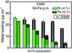
The parental Ni(OH)2 and FeOOH oxide catalysts were synthesized according to a reported solvothermal method.20 Two ink formulations of the individual parental oxides were mixed by brief sonication (see ESI† for details). Scanning electron microscopy (SEM) confirmed that both Ni(OH)2 and Fe(OOH) were particle-like in the size range of ∼200–500 nm, whereas the Ni100(OH)2 catalyst was composed of typical randomly stacked hydroxide sheets (Fig. S1a and b, ESI†).36,37 The physical mixture (“p.m.”) appeared as a composite of the two, and the SEM-EDX elemental mappings indicated that Ni and Fe were more or less well distributed (Fig. S1c and d, ESI†). The local mixing will be further investigated below. The activities were evaluated using a rotating disk electrode (RDE) setup (see details in ESI†). A composition-controlled activity was evident in our physically mixed catalysts, where in fact the activity of some of the Ni + Fe p.m. catalysts exceeded the activity of the co-s. catalysts (Fig. 1a). The turnover frequency per total metal ion (TOFNi+Fe) at η = 300 mV was highest around 30–35% Fe-content. Compared to the co-synthesized catalysts, the activity maximum was shifted to higher Ni-content in the physically mixed catalysts (Fig. 1b). The Ni65 + Fe35 p.m. catalyst had a highest turnover frequency of 0.1 s−1, and exhibited an overpotential of 298 mV at 10 mA cm−2 and a Tafel slope of 37 mV dec−1 (Fig. S2a, b, eqn (S1)–(S2) and Table S1, ESI†). The faradaic efficiency (FEO2) was estimated to be 92% for a Ni50 + Fe50 p.m. catalyst (Fig. S2c, d and eqn (S3)–(S5), ESI†). We conclude that our physically mixed catalysts exhibit intrinsic turnover rates competitive to other Ni–Fe catalysts (see Table S2 for literature comparison, ESI†).38 The only study known to us including physical mixtures of oxides was reported by Gong et al.,16 wherein the resulting β-Ni(OH)2NP + FeOxNP in contrast showed inferior activity to the co-synthesized catalyst. This is surprising since several studies have shown that active Ni–Fe catalysts can be obtained by exposing Ni electrodes to an electrolyte containing Fe3+ impurities.33–35,39 In our Ni + Fe catalysts, the Ni2+ → Ni3+ redox peaks were positioned at strikingly high cathodic potentials (by ∼50 mV) compared to that of the co-s. Ni–Fe catalysts, and the integrated area (redox charge) was relatively higher (Fig. 1c and Fig. S3, ESI†). A similar difference in peak position was reported by Burke Stevens et al.33 of an electrodeposited Ni(OOH) cycled in an Fe3+ spiked electrolyte and a co-deposited Ni–Fe catalyst, which was explained by a smaller number of Fe ions substituting “bulk” lattice sites. At a given nominal composition, it is hence likely that our Ni + Fe p.m. catalysts have an average lower number of mixed Ni–Fe sites. In situ UV-vis showed that the absorption perfectly matched the redox peaks in our Ni + Fe catalysts, which coincided with an increase in the absorption around ∼500 nm assigned to the oxidized Ni3+/4+ species (Fig. 1d and Fig. S4, S5, ESI†).20 The Ni100 catalyst underwent a concomitant coloration from transparent to dark; however, increasing the Fe-content gradually prevented this color change in the Ni + Fe catalysts (Fig. S5a, ESI†), in agreement with our earlier studies of the co-s. Ni–Fe catalysts.20 Total reflection X-ray fluorescence (TXRF) spectroscopy revealed a significant loss of Fe after the OER characterization protocol (see Fig. 2). Dissolution of Fe has been reported before in Ni–Fe catalysts; however, not to this extent.40,41 Despite this, we noticed a steady increase in activity during the characterization along with an anodic peak shift (Fig. S6, ESI†). A less significant shift was seen for the Ni100(OH)2 catalyst, suggesting that Fe-impurities were not the main cause of this “activation”. A similar activation was seen for the co-s. Ni–Fe catalysts, but less pronounced than for the Ni + Fe catalysts (Fig. S7, ESI†). This suggests that the activation may partly be due to other processes such as hydration in addition to possible compositional changes. The OER activities after correction for the dissolution of metals are shown in Fig. S2e (ESI†).
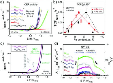 | ||
| Fig. 1 (a) The OER activity (CVs at 10 mV s−1) of physically mixed (p.m.) Ni + Fe catalysts and a co-synthesized (co-s.) Ni–Fe catalyst. (b) TOFNi+Fe per total metal ion at η = 300 mV at a total metal loading of ∼25 μgNi+Fe cm−2. (c) CVs of the Ni65 + Fe35 p.m. and co-s. Ni65Fe35 catalysts in as-received KOH. The position of the redox peaks and activity at 1.53 V is indicated with dotted lines. (d) In situ UV–vis absorption at λ = 500 nm (average between 400–600 nm) during potential staircase-wise steps. The physically mixed catalysts were measured in Fe-free KOH18 and the Fe100(OOH) catalyst in as-received KOH unless stated otherwise. | ||
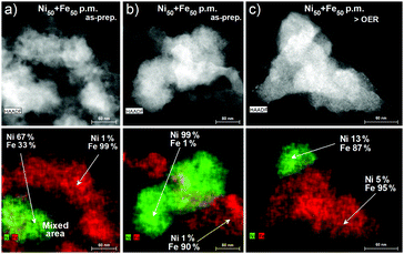
To better resolve the mixing and local atomic composition in the physically mixed catalysts, we used high-angle annular dark field imaging – scanning transmission electron microscopy (HAADF-STEM) and elemental mapping. Investigations of the as-prepared Ni50 + Fe50 p.m. catalyst showed that the parental Ni(OH)2 and Fe(OOH) particles did not form a complete uniformly mixed phase (Fig. 3a, b and Fig. S8a–e, ESI†). EDX elemental mappings showed that only a small fraction of the particles formed a direct contact area (mixed Ni–Fe sites) and other areas were not in contact at all. The largest mixing occurred in the direct contact areas, and further away from this area Ni-rich and Fe-rich phases were clearly visible. In these half mixed Ni(OH)2 and Fe(OOH) phases, there were about 1–2% of Fe and Ni impurities homogenously distributed over the entire particles, respectively. The mixing in the direct contact area is not well defined, and depends on the size and the thickness of the particles. After exposure to catalytic potential (1.63 V, 30 min in purified 0.1 M KOH), the impurities of both Ni and Fe increased in the respective phase segregated Ni-rich and Fe-rich areas of the Ni50 + Fe50 p.m. catalyst. The Ni(OH)2 particles after OER contained ∼4–13% of Fe impurities, and the Fe(OOH) particles ∼4–8% of Ni impurities (Fig. 3c and Fig. S8f–j, ESI†). On average, the levels of impurities are in accordance with the limitation of ∼25–30% solubility of Fe in the Ni(OH)2/OOH phase.27,33 We note that all catalyst particles had an oxide contribution of ∼75%, which was present in both the Ni and Fe phases. Investigations of the as-prepared Ni100(OH)2 and Fe(OOH) materials showed that both contained a very low amount of impurities (<0.1%), see Fig. S9 (ESI†). Therefore, the elevated impurities in the mixed Ni + Fe catalysts are likely a result of the mixing. After OER, a small increase in Fe impurities in the Ni100(OH)2 catalyst was observed despite that the electrolyte had been purified (∼1%), showing the difficulty to remove all sources of impurities. The more significant increase of impurities in the Ni50 + Fe50 p.m. catalyst during the OER may therefore be regarded to compositional changes, likely facilitated by the observed dissolution. For comparison, we investigated a co-synthesized Ni40Fe60 catalyst, which we confirmed was composed of a uniformly mixed Ni–Fe phase in contrast to the physically mixed catalyst (Fig. S10, ESI†). Our results therefore confirm that at any given nominal composition, the number of mixed Ni–Fe sites in our physically mixed Ni + Fe catalysts is smaller, and also smaller compared to the co-synthesized Ni–Fe catalysts at the actual composition. The intrinsic turnover rates in our Ni + Fe p.m. catalysts are therefore likely to be highly underestimated, assuming that a mixed Ni–Fe site is required for efficient catalysis, as proposed by Xio et al.25 based on DFT calculations.
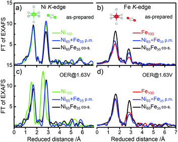
The local atomic structure was further investigated using in situ X-ray absorption spectroscopy (XAS) at the metal K-edges. The as-prepared Ni65 + Fe35 p.m. catalyst exhibited octahedral coordination with metal centers in Ni2+ and Fe3+ oxidation states, in agreement with the co-s. Ni65Fe35 catalyst and the parental Ni(OH)2 and Fe(OOH) catalysts (Fig. 4 and Fig. S11, S12, ESI†).20 The 2nd FT-EXAFS amplitude representing the Fe–M coordination shell of the as-prepared Ni65 + Fe35 p.m. catalyst was a bit higher than the parental Fe100(OOH), which may indicate a small modulation of the Fe phase. The amplitudes were on the other hand lower than in the co-s. Ni65Fe35 catalyst showing that the bulk was not modified to the same extent, in agreement with the other data. Surprisingly, application of a catalytic potential of 1.63 V did not result in a Ni K-edge shift of the Ni65 + Fe35 p.m. catalyst, as expected for the Ni2+→ Ni3+/4+ oxidation. Therefore, all metal centers remained as low-valent Ni2+. The parental Ni100(OH)2 on the other hand exhibited an edge shift of +2.6 eV as expected for “complete oxidation” to Ni3.7+.20 None of the investigated catalysts exhibited potential-induced changes at the Fe K-edge and therefore are compatible with Fe3+ throughout the reaction cycle.20 This concludes that Fe sites in our Ni + Fe p.m. catalyst are more similar to the sites in the parental Fe100(OOH) – in contrast to the Ni sites – which are more similar to the sites in the co-s. Ni65Fe35 catalyst. Operando XAS of a Ni50 + Fe50 p.m. catalyst also confirmed the absence of oxidation state changes, in accordance with the quasi-in situ XAS (Fig. S13, ESI†). It should be kept in mind that changes below ∼10% may be difficult to observe since XAS is a bulk method. Simulated fit parameters are listed in Tables S3 and S4, ESI.†
It is somewhat unexpected that a relatively small amount of Fe contaminations in the Ni(OH)2 phase is sufficient to suppress nearly the entire visible population of oxidized Ni3+/4+. This is in agreement with our observations in the co-s. Ni–Fe catalysts that ∼10% is sufficient to shift the equilibrium to the Ni2+ state during OER,20 also supported by other studies.22,23,25 An interesting similar effect of Fe was reported by Klaus et al.,40 where a sputtered Fe top-layer on a sublayer of Ni inhibited the electrochemical conversion of metallic Ni to Ni(OH)2/NiOOH, and hence Fe was proposed to act as a “capping” layer. It is therefore possible that the Fe(OOH) not incorporated into the Ni(OH)2 phase may introduce similar unwanted effects.
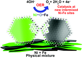
To summarize, our XAS data is compatible with formation of new “interfacial” Ni–Fe sites in our physically mixed catalysts. This includes formation of a new atomically intermixed phase with bridging (physio-chemical) Ni–O–Fe motifs, which according to HAADF-STEM and mappings are restricted to some local spots on the particles that form a direct contact area (depicted in Fig. 5). At a given composition, the number of mixed sites in the Ni + Fe p.m. catalysts is smaller in comparison to the co-synthesized catalysts. It is therefore remarkable that similar current densities are achieved with a different number of active sites. In recent discussions “surface”, “edge” or “defect” sites were proposed as more reactive towards the OER than “bulk” sites.30,33 In line with these discussions – the presence of two types of sites (or location) with distinct O2 turnover rates would offer a feasible explanation for the unexpectedly high activity in our physically mixed Ni–Fe catalysts. We speculate whether these highly active sites are more “exposed” sites such as surface or edge sites.
We have shown that highly active OER catalysts can be prepared by facile mixing of distinct Ni(OH)2 and Fe(OOH) phases, where a fraction self-assemble into mixed Ni–Fe sites, responsible for the activity.
We thank Helmholtz-Zentrum Berlin (HZB) for measurements at KMC-1 and KMC-3 at BESSY II (thanks Marcel Mertin, Ivo Zizak, Götz Schuck). We also thank Ulrich Gernert and Christoph Fahrenson at ZELMI Zentrum Berlin for SEM-EDX.
Conflicts of interest
There are no conflicts to declare.Notes and references
- N. S. Lewis and D. G. Nocera, Proc. Natl. Acad. Sci. U. S. A., 2006, 103, 15729–15735 CrossRef PubMed.
- H. Dau, C. Limberg, T. Reier, M. Risch, S. Roggan and P. Strasser, ChemCatChem, 2010, 2, 724–761 CrossRef.
- D. Gust, T. A. Moore and A. L. Moore, Acc. Chem. Res., 2009, 42, 1890–1898 CrossRef CAS PubMed.
- J. Luo, J.-H. Im, M. T. Mayer, M. Schreier, M. K. Nazeeruddin, N.-G. Park, S. D. Tilley, H. J. Fan and M. Grätzel, Science, 2014, 345, 1593–1596 CrossRef CAS.
- L. Wang, F. Dionigi, N. T. Nguyen, R. Kirchgeorg, M. Gliech, S. Grigorescu, P. Strasser and P. Schmuki, Chem. Mater., 2015, 27, 2360–2366 CrossRef CAS.
- S. Dresp, F. Luo, R. Schmack, S. Kuhl, M. Gliech and P. Strasser, Energy Environ. Sci., 2016, 9, 2020–2024 RSC.
- C. W. Li and M. W. Kanan, J. Am. Chem. Soc., 2012, 134, 7231–7234 CrossRef CAS PubMed.
- H. Mistry, A. S. Varela, C. S. Bonifacio, I. Zegkinoglou, I. Sinev, Y.-W. Choi, K. Kisslinger, E. A. Stach, J. C. Yang, P. Strasser and B. R. Cuenya, Nat. Commun., 2016, 7, 12123 CrossRef PubMed.
- I. C. Man, H. Y. Su, F. Calle-Vallejo, H. A. Hansen, J. I. Martinez, N. G. Inoglu, J. Kitchin, T. F. Jaramillo, J. K. Norskov and J. Rossmeisl, ChemCatChem, 2011, 3, 1159–1165 CrossRef CAS.
- Y. Lee, J. Suntivich, K. J. May, E. E. Perry and Y. Shao-Horn, J. Phys. Lett., 2012, 3, 399–404 CAS.
- T. Reier, H. N. Nong, D. Teschner, R. Schlögl and P. Strasser, Adv. Energy Mater., 2017, 7, 1601275 CrossRef.
- M. Risch, F. Ringleb, M. Kohlhoff, P. Bogdanoff, P. Chernev, I. Zaharieva and H. Dau, Energy Environ. Sci., 2015, 8, 661–674 RSC.
- C. C. L. McCrory, S. Jung, I. M. Ferrer, S. M. Chatman, J. C. Peters and T. F. Jaramillo, J. Am. Chem. Soc., 2015, 137, 4347–4357 CrossRef CAS.
- W. T. Hong, M. Risch, K. A. Stoerzinger, A. Grimaud, J. Suntivich and Y. Shao-Horn, Energy Environ. Sci., 2015, 8, 1404–1427 RSC.
- R. D. L. Smith, M. S. Prevot, R. D. Fagan, S. Trudel and C. P. Berlinguette, J. Am. Chem. Soc., 2013, 135, 11580–11586 CrossRef CAS.
- M. Gong, Y. Li, H. Wang, Y. Liang, J. Z. Wu, J. Zhou, J. Wang, T. Regier, F. Wei and H. Dai, J. Am. Chem. Soc., 2013, 135, 8452–8455 CrossRef CAS.
- M. W. Louie and A. T. Bell, J. Am. Chem. Soc., 2013, 135, 12329–12337 CrossRef CAS.
- L. Trotochaud, S. L. Young, J. K. Ranney and S. W. Boettcher, J. Am. Chem. Soc., 2014, 136, 6744–6753 CrossRef CAS.
- D. A. Corrigan, J. Electrochem. Soc., 1987, 134, 377–384 CrossRef CAS.
- M. Görlin, P. Chernev, J. Ferreira de Araújo, T. Reier, S. Dresp, B. Paul, R. Krähnert, H. Dau and P. Strasser, J. Am. Chem. Soc., 2016, 138, 5603–5614 CrossRef.
- S. Dresp, F. Dionigi, S. Loos, J. Ferreira de Araujo, C. Spöri, M. Gliech, H. Dau and P. Strasser, Adv. Energy Mater., 2018, 8, 1800338 CrossRef.
- R. D. L. Smith, C. Pasquini, S. Loos, P. Chernev, K. Klingan, P. Kubella, M. R. Mohammadi, D. González-Flores and H. Dau, Energy Environ. Sci., 2018, 11, 2476–2485 RSC.
- D. González-Flores, K. Klingan, P. Chernev, S. Loos, M. R. Mohammadi, C. Pasquini, P. Kubella, I. Zaharieva, R. D. L. Smith and H. Dau, Sustainable Energy Fuels, 2018, 2, 1986–1994 RSC.
- M. K. Bates, Q. Jia, H. Doan, W. Liang and S. Mukerjee, ACS Catal., 2016, 6, 155–161 CrossRef CAS.
- H. Xiao, H. Shin and W. A. Goddard, Proc. Natl. Acad. Sci. U. S. A., 2018, 115, 5872–5877 CrossRef CAS.
- N. Li, D. K. Bediako, R. G. Hadt, D. Hayes, T. J. Kempa, F. von Cube, D. C. Bell, L. X. Chen and D. G. Nocera, Proc. Natl. Acad. Sci. U. S. A., 2017, 114, 1486 CrossRef CAS PubMed.
- D. Friebel, M. W. Louie, M. Bajdich, K. E. Sanwald, Y. Cai, A. M. Wise, M.-J. Cheng, D. Sokaras, T.-C. Weng, R. Alonso-Mori, R. C. Davis, J. R. Bargar, J. K. Nørskov, A. Nilsson and A. T. Bell, J. Am. Chem. Soc., 2015, 137, 1305–1313 CrossRef CAS PubMed.
- D. Wang, J. Zhou, Y. Hu, J. Yang, N. Han, Y. Li and T.-K. Sham, J. Phys. Chem. C, 2015, 119, 19573–19583 CrossRef CAS.
- Z. K. Goldsmith, A. K. Harshan, J. B. Gerken, M. Voros, G. Galli, S. S. Stahl and S. Hammes-Schiffer, Proc. Natl. Acad. Sci. U. S. A., 2017, 114, 3050–3055 CrossRef CAS.
- J. Y. C. Chen, L. Dang, H. Liang, W. Bi, J. B. Gerken, S. Jin, E. E. Alp and S. S. Stahl, J. Am. Chem. Soc., 2015, 137, 15090–15093 CrossRef CAS.
- B. M. Hunter, N. B. Thompson, A. M. Müller, G. R. Rossman, M. G. Hill, J. R. Winkler and H. B. Gray, Joule, 2018, 2, 747–763 CrossRef CAS.
- H. S. Ahn and A. J. Bard, J. Am. Chem. Soc., 2016, 138, 313–318 CrossRef CAS.
- M. Burke Stevens, C. D. M. Trang, L. J. Enman, J. Deng and S. W. Boettcher, J. Am. Chem. Soc., 2017, 139, 11361–11364 CrossRef PubMed.
- H. Yin, L. Jiang, P. Liu, M. Al-Mamun, Y. Wang, Y. L. Zhong, H. Yang, D. Wang, Z. Tang and H. Zhao, Nano Res., 2018, 11, 3959–3971 CrossRef CAS.
- J. Wang, L. Gan, W. Zhang, Y. Peng, H. Yu, Q. Yan, X. Xia and X. Wang, Sci. Adv., 2018, 4, eaap7970 CrossRef PubMed.
- D. S. Hall, D. J. Lockwood, C. Bock and B. R. MacDougall, Proc. R. Soc. London, Ser. A, 2015, 471, 1–65 Search PubMed.
- M. P. Browne, S. Stafford, M. O'Brien, H. Nolan, N. C. Berner, G. S. Duesberg, P. E. Colavita and M. E. G. Lyons, J. Phys. Chem. A, 2016, 4, 11397–11407 CAS.
- F. Dionigi and P. Strasser, Adv. Energy Mater., 2016, 6, 1600621 CrossRef.
- J. D. Michael, E. L. Demeter, S. M. Illes, Q. Fan, J. R. Boes and J. R. Kitchin, J. Phys. Chem. C, 2015, 119, 11475–11481 CrossRef CAS.
- S. Klaus, M. W. Louie, L. Trotochaud and A. T. Bell, J. Phys. Chem. C, 2015, 119, 18303–18316 CrossRef CAS.
- F. D. Speck, K. E. Dettelbach, R. S. Sherbo, D. A. Salvatore, A. Huang and C. P. Berlinguette, Chem, 2017, 2, 590–597 CAS.
Footnote |
| † Electronic supplementary information (ESI) available: Experimental details, electrochemical characterization, UV-vis, Faradaic efficiency calculations, and XAS simulations and fit parameters. See DOI: 10.1039/c8cc06410e |
| This journal is © The Royal Society of Chemistry 2019 |

