 Open Access Article
Creative Commons Attribution 3.0 Unported Licence
ETFE-based anion-exchange membrane ionomer powders for alkaline membrane fuel cells: a first performance comparison of head-group chemistry†
Ana Laura
Gonçalves Biancolli
 ad,
Daniel
Herranz
 cd,
Lianqin
Wang
 d,
Gabriela
Stehlíková
ed,
Rachida
Bance-Soualhi
 d,
Julia
Ponce-González
 d,
Pilar
Ocón
c,
Edson A.
Ticianelli
a,
Daniel K.
Whelligan
 d,
John R.
Varcoe
 *d and
Elisabete I.
Santiago
 bd
bd
aInstituto de Química de São Carlos, Universidade de São Paulo, São Carlos, Brazil
bInstituto de Pesquisas Energéticas e Nucleares – IPEN-CNEN/SP, São Paulo – SP, Brazil
cDepartamento de Quimica Fisica Aplicada, Universidad Autonoma de Madrid, Madrid, Spain
dDepartment of Chemistry, The University of Surrey, Guildford GU2 7XH, UK. E-mail: j.varcoe@surrey.ac.uk
eDepartment of Inorganic Chemistry, Faculty of Natural Sciences, Comenius University, 84215 Bratislava, Slovakia
First published on 19th November 2018
Abstract
In the last few years, the development of radiation-grafted powder-form anion-exchange ionomers (AEI), used in combination with anion-exchange membranes (AEM), has led to the assembly of AEM-based fuel cells (AEMFC) that routinely yield power densities ranging between 1–2 W cm−2 (with a variety of catalysts). However, to date, only benzyltrimethylammonium-type powder AEIs have been evaluated in AEMFCs. This study presents an initial evaluation of the relative AEMFC power outputs when using a combination of ETFE-based radiation-grafted AEMs and AEIs containing three different head-group chemistries: benzyltrimethylammonium (TMA), benzyl-N-methylpyrrolidinium (MPY), and benzyl-N-methylpiperidinium (MPRD). The results from this study strongly suggest that future research should focus on the development and operando long-term durability testing of AEMs and AEIs containing the MPRD head-group chemistry.
Introduction
Fuel cells are considered an efficient and clean energy conversion technology, which can offer superior energy efficiencies to conventional technologies, such as combustion engines. Such devices have been considered promising, due to the ability to directly convert chemical energy (provided from a fuel, e.g. H2) into electrical energy, with wide applicability in mobile (transportation), portable, and stationary systems.1,2In the class of low-temperature fuel cells, alkaline fuel cells (AFC) have regained relative importance due to the development of high-performance anion-exchange membranes (AEM). The main advantages of an anion-exchange membrane fuel cell (AEMFC) over current proton exchange membrane fuel cells (PEMFC) are: (i) lower activation overpotential at the cathode promising the use of non-Pt-group catalysts, (ii) a less corrosive environment allowing the use of cheaper metallic components, (iii) reduced gas and alcohol crossover, and (iv) alternate water management.3,4 AEMs are ionomeric polymers, in the same way as the proton exchange membranes used in PEMFCs, but where hydroxyl ions (OH−) are ionically bound to polymer-bonded (positively charged) quaternary ammonium groups, which form the anion conducting network.5
Despite the improvements in the development of AEMs, AEMFCs have (until recently) presented poorer performances in comparison to the more well-stablished PEMFCs. One of the reasons for this is associated with the inferior OH− conductivity of many AEMs in comparison to H+ conduction in PEMs; this often lead to the use of AEMs with higher IECs (ion exchange capacity), leading to the risk of additional mechanical instabilities.6 This poor AEMFC performance is also due to the unavailability of suitable anion-exchange ionomer (AEI) candidates, which are needed to impart OH− conducting in the catalyst layers of the electrodes (more on this later). The chemical, thermal and mechanical stabilities of AEMs is strongly dependent on the nature of the (anion conducting) functional groups and also the backbone chain. Besides temperature, the main cause of degradation of various anion conducting groups and polymer chains is the alkalinity of the medium (high pH), a problem that is especially severe in materials containing lower hydration levels.7,8 AEMs are formed using a variety of backbones, including non-fluorinated, partially fluorinated or fully fluorinate polymers, such as poly(ethylene), polysulfones, poly(phenylene oxide)s (PPO), poly(phenylene)s, polybenzimidazoles (PBI), and modified poly(ethylene-co-tetrafluoroethylene) (ETFE). The covalently-linked side-chain quaternary ammonium cationic groups are responsible for conduction of the anions (OH−).
Such side-chains can be incorporated onto the backbone of polymer precursors by copolymerization of monomers using the radiation-grafting technique, which allows the use of pre-fabricated polymeric films, leading to facile AEMs production.9 The desired objective of radiation-grafting is to create active sites on the polymer chains onto which grafted polymer side-chains can be attached (when placed in contact with suitable monomers). A major advantage of this technique is that materials with different head-group chemistries can be synthesised from the same precursor polymer electrolytes with similar ion-exchange capacities (as an aside, this is demonstrated by the data presented in Fig S1 in the ESI† related to the development of different imidazolium-based radiation-grafted AEMs). However, other modifications induced by polymer irradiation can occur, including undesirable scission of the backbone chain (producing mechanically weaker materials), formation of covalent cross-links, and the introduction of (reactive) unsaturated chemical groups.10
Radiation-grafted anion-exchange polymer electrolytes have been prepared by using both simultaneous-(mutual)-irradiation or pre-irradiation induced grafting methods. In general, the simultaneous method results in the production of undesired, un-grafted homopolymers, while polymers with lower degrees of grafting are typically produced with the pre-irradiation method (often then requiring higher radiation doses that will result in more polymer damage).11
The lack of optimised gas diffusion electrodes (GDE) for the MEA (membrane-electrode assembly), which combine ionic and electronic conductivity with efficient transport of reactants, products and water in the three-phase boundary, has impeded development of high-performance AEMFCs.12 In this context, the AEI plays an essential role on the GDE's catalyst layer (CL), with active participation in the ion transport to and from the surfaces of the electrocatalysts.13,14 The AEIs, often supplied in solution or dispersion form, combine the role of binder and OH− ion conductor in the CL.15 Similar to the AEMs, the main requirements for the use in GDE are the combination of high ion conductivity and stability in alkaline media, especially in the cathode where dry out leads to reduced conductivity and durabilities.16–18 The development of AEIs is much more early stage (cf. AEMs) due to the difficulty of formulating dispersions or ionomer solutions without deterioration of their chemical properties. AEI concepts based on both cross-linked and uncross-linked polymers have been proposed,12,19–23 but their performances in AEMFCs is still poor compared to the perfluorosulfonic acid (PFSA) ionomers used in PEMFCs. Advances in AEI development are desperately required.
In 2014, Poynton et al. first reported the use of a powdered AEI in AEMFCs.24 The AEI powder was prepared by the radiation-grafting of VBC (vinylbenzyl chloride) monomer onto ETFE powders followed by functionalisation with trimethylamine to form the quaternary ammonium forms, which can then be directly used within the CLs. Subsequently, this AEI powder has been used in combination with optimised AEMs leading to impressive AEMFC performances;25–29 this demonstrates that ionomer powders can be effectively incorporated into CLs, opening up new opportunities for high performance AEMFCs.
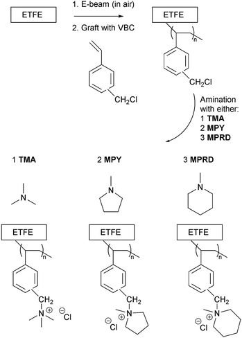
In this context, this article describes the synthesis and characterization of irradiated ETFE-based AEI powders (Scheme 1) that have been functionalised with three different cationic head-groups (previously only studied for radiation-grafted AEMs30 and not for AEI powders): benzyltrimethylammonium (TMA), benzyl-N-methylpyrrolidinium (MPY), or benzyl-N-methylpiperidinium (MPRD). This study will evaluate these three different types of AEI powder with respect of AEMFC power outputs (alongside their corresponding functionalised AEMs). The results from this study can then be used to direct future (time intensive and expensive) operando durability studies with down-selected head-group chemistry options. The effect of using different batches of VBC-grafted ETFE (in electrode fabrication) and repeat electrodes (with the same AEI powder batch) are also evaluated.
Materials and methods
Preparation of anion-exchange membranes (AEM)
This work involved the synthesis of radiation-grafted AEMs based on ETFE polymer films (Nowofol, 25 μm thick), which were electron-beamed in presence of air (4.5 MeV Dynamatron Continuous Electron Beam Unit, STERIS Synergy Health, South Marston, UK) with absorbed doses controlled by the number of passes (10 kGy per pass).24,28 The ETFE films were exposed to a 30 or 40 kGy absorbed dose and stored at −40 °C before grafting.The e-beam-treated ETFE films (13 × 13 cm) were immersed in aqueous mixtures containing 5% vol. vinylbenzyl chloride monomer (VBC, Sigma-Aldrich product code 338729, 97% purity, mixture of 3- and 4-isomers, no prior removal of the 700–1100 ppm nitromethane or 50–100 ppm tert-butylcatechol inhibitors) and 1% vol. 1-octyl-2-pyrrolidone dispersant (Sigma-Aldrich) in glass vessels. After the grafting mixtures were purged with N2 (2 h) the vessels were sealed and heated at 70 °C for 16 h. After grafting was complete, the films were removed and washed multiple times with toluene to remove excess unreacted VBC and any traces of VBC homopolymer that may be present. The resulting intermediate VBC-grafted films were subsequently dried at 70 °C for 5 h in a vacuum oven.
The VBC-grafted films were then aminated with three different amines by immersion in aqueous solutions of various concentrations for various durations (exact conditions summarised in Table 1). The amines used were trimethylamine (TMA), N-methylpyrrolidine (MPY) and N-methylpiperidine (MPRD). After amination, the resulting crude AEMs (predominantly in the Cl− anion forms) were washed multiple times with ultrapure water (UPW). They were then ion-exchange to the pure Cl− anion forms via immersion in aqueous NaCl (1 mol dm−3) overnight at room temperature (with at least 2 changes of solution during this time). The final Cl− form AEMs were obtained after rigorous washing in UPW at room temperature (ensuring no Na+ co-ions and no excess Cl− counter ions were present, such that the only Cl− counter ions present were those charge balancing the positive charges on the grafted polymer chains). All AEMs were stored in UPW until required.
| AEM(TMA) | AEM(MPY) | AEM(MPRD) | |
|---|---|---|---|
| a The in-plane Cl− anion conductivity of the AEMs in water at 60 °C from 4-probe electrochemical impedance spectroscopy data. b Gravimetric water uptakes at room temperature. c Hydrated AEM thickness at room temperature. d Dehydrated AEM thickness at room temperature. e Through-plane swelling (=100 × (thyd − tdehyd)/tdehyd).29 f In-plane swelling (=100 × Ahyd − Adehyd)/Adehyd where A is membrane area. | |||
| Radiation dose | 30 kGy | 40 kGy | 40 kGY |
| VBC concentration | 5% vol. | 5% vol. | 5% vol. |
| Graft time/temp. | 16 h at 70 °C | 16 h at 70 °C | 16 h at 70 °C |
| Amination solution (aq.) concentration | 45% vol. | 50% vol. | 15% vol. |
| Amination time | 24 h | 16 h | 18 h |
| Amination temp. | Room temp. | 70 °C | 60 °C |
| IEC/mmol g −1 | 2.05 ± 0.05 | 2.09 ± 0.08 | 1.73 ± 0.03 |
| σ/mS cm −1 | 46.1 ± 0.2 | 43.3 ± 3.1 | 30.8 ± 1.2 |
| WU (%) | 67 ± 7 | 121 ± 5 | 84 ± 8 |
| t hyd /μm | 56 ± 3 | 70 ± 2 | 55 ± 2 |
| t dehyd /μm | 45 ± 2 | 47 ± 2 | 43 ± 2 |
| TPS (%) | 24 | 49 | 28 |
| IPS (%) | 16 | 31 | 18 |
Characterisation of the AEMs
The AEMs were characterised in the Cl− forms using the routine procedures detailed in ref. 29 (without modification): these include the measurement of ion-exchange capacity (IEC), 4-probe (in-plane) conductivities in water, and gravimetric water uptakes. These key properties are summarised in Table 1. We note that the AEMs swell more in the thickness direction than in the in-plane direction: this is important for future long-term mechanical durabilities when operated in AEMFCs. Raman spectra of the VBC-grafted ETFE-films and the final AEMs were collected using Renishaw InVia Raman Spectrometer (laser λ = 785 nm) equipped with CCD and Leica microscope.Preparation and initial characterisation of the powder anion-exchange ionomers (AEI)
The methodology for synthesising the radiation-grafted ETFE-based powder AEIs was similar to that used for producing the AEMs above. These procedures will not be repeated in detail; however, modifications are highlighted in the following text.The ETFE powders (Fluon® Z-8820X, AGC Europe, particle diameters 20–30 μm) were irradiated in air to an absorbed dose of 100 kGy using the same electron-beam facility. The e-beamed powders (up to 20 g per batch) were grafted using aqueous grafting solutions with the conditions summarised in Table 2. The resulting intermediate VBC-grafted powders were recovered by filtration, washed with toluene and subsequently dried at 50 °C for 5 h in a vacuum oven. The AEI powders when then aminated using the conditions summarised in Table 2. After ion-exchange to the pure Cl− anion forms and thorough washing with UPW (additional filtration steps needed to recover the modified powders) the final AEI powders were then dried in a vacuum oven at 50 °C overnight before being subjected to ball milling for 8 h to achieve deagglomeration of the powder particles. The IECs of the powder AEIs were recorded using exactly the same method that was used for the AEMs.29 Raman spectra of the ETFE precursor powder, the VBC-grafted powders and the final powder AEIs were collected using the same Renishaw InVia Raman spectrometer as used with the AEMs.
| AEI(TMA) | AEI(MPY) | AEI(MPRD) | |
|---|---|---|---|
| Radiation dose | 100 kGy | 100 kGy | 100 kGy |
| VBC concentration | 5% vol. | 5% vol. | 5% vol. |
| Graft time/temp. | 24 h at 60 °C | 24 h at 60 °C | 24 h at 60 °C |
| Amination solution (aq) concentration | 45% vol. | 50% vol. | 15% vol. |
| Amination time | 24 h | 16 h | 18 h |
| Amination temp. | Room temp. | 50 °C | 60 °C |
| IEC/mmol g −1 | 2.01 ± 0.01 | 1.90 ± 0.02 | 1.99 ± 0.01 |
Scanning electronic microscopy (SEM) and energy-dispersive X-ray spectroscopy (EDX) of the powder AEIs
The powder AEIs (and the electrodes fabricate from them – see next section) were evaluated morphologically using SEM. A small amount of each AEI (and the grafted precursor) was deposited onto a sample holder using epoxy resin and subsequently coated with Au film (9 nm thickness). The Field Emission Scanning Electron Microscopy (FE-SEM) images, and the associated EDX elemental (C, N, O, Cl, F, Pt and Ru) data, were obtained using a JEOL JSM-7100F instrument.Electrode and membrane-electrode assembly (MEA) fabrication
The catalysed gas diffusion electrode (GDE) method was used for fabricating the AEMFC electrodes. For each cathode GDE, Pt/C (Alfa Aesar, Johnson Matthey HiSPEC 4000, 40% wt Pt) and AEI powder (20% wt of the total solid mass for AEI(TMA) and 30% wt for AEI(MPY) and AEI(MPRD)) were mixed together with 1 mL of water and 9 mL of propan-2-ol. This cathode catalyst ink was homogenised in ultrasound for 30 min, sprayed onto a Toray TGP-H-60 carbon paper gas diffusion layer (GDL, non-teflonated), and then dried in air. For the anode GDEs, PtRu/C (Alfa Aesar, Johnson Matthey HiSPEC 12100, 50% wt Pt and 25% wt Ru) catalyst was used as the catalyst. The geometric areas of all GDEs were 5.0 cm2 and the Pt loadings for all anodes and cathodes were 0.40 ± 0.03 mgPt cm−2.Prior to MEA assembly, the electrodes and AEM under test were immersed in aqueous KOH (1 mol dm−3) for 1 h, followed by thorough washing with UPW (to remove excess K+ and OH− ions). Each membrane-electrode assembly (MEA) was assembled by placing the anode, cathode, and AEM (4 cm × 4 cm), to be tested together, between two graphite plates machined with serpentine type distribution channels (the 5 cm2 fuel cell fixture used was supplied by Scribner Associates, USA) and applying a torque of 5.5 N m. It is important to note that unlike with PEMFCs, no prior hot-pressing was used to produce the MEAs: the MEAs hot-press in situ on fuel cell start-up.
Anion-exchange membrane fuel cell (AEMFC) testing
The H2/O2 AEMFC tests of each MEA fabricated were conducted using an 850C fuel cell test station (Scribner Associates, USA). All AEMFC tests were conducted at 60 °C with 1 dm3 min−1 gas supplies. The exact test conditions used for each test are detailed in the relevant figure captions. All gases were supplied without back-pressurisation. The AEMFCs were “activated” via operation at 0.5 V until a steady current was achieved (min. 1 h). Polarisation curves were collected in galvanostatic mode. In situ area specific resistances (ASR) were collected using the 850C's internal current interrupt method.Results and discussion
Initial AEM and AEI characterisation
As stated before, and to aid routine characterisations,11 we always conduct initial analyses of our AEMs (for select properties) in the Cl− anion forms before they have been exposed to any extreme pH environments (that may subtly change their properties) and to eliminate CO2-derived interferences processes (that will change OH− forms of AEMs to CO32−/HCO3− forms). As such, our standard procedure for performance testing means we only convert the AEIs and AEMs into the OH− forms immediately before device testing (see AEMFC testing description above).The IECs for the Cl− anion form AEMs and AEIs are reported in Tables 1 and 2, respectively. The IECs of the powder AEIs were similar, while the IEC of AEM(MPRD) was slightly lower than for AEM(TMA) and AEM(MPY). This contributed towards the lower conductivity profile of AEM(MPRD) across all application relevant temperatures (Fig. 1). Our previous study of thicker ETFE-based AEMs made using TMA, MPY, and MPRD (from the radiation-grafting of 50 μm ETFE as opposed to the 25 μm used in this study) showed that MPRD-based radiation-grafted AEMs intrinsically present much higher water-uptakes compared to TMA- and MPY-based AEMs.30 The use of a lower IEC for AEM(MPRD) in this study was intended to prevent an excessive water uptake and swelling, which would have led to an AEM with undesirably low mechanical properties11 (it is the AEM, not the AEI, that is required for safe H2 and O2 gas separation characteristics inside the AEMFCs).
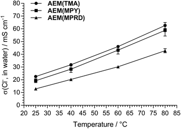 | ||
| Fig. 1 A relative comparison of the Cl− anion conductivities of the AEMs used in this study (fully hydrated in water, 4-probe electrochemical impedance spectroscopy data). | ||
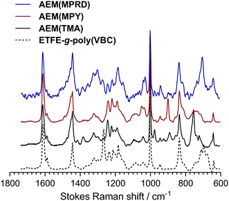
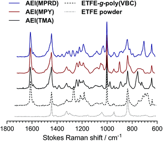
The Raman spectra of the AEMs are presented in Fig. 2. These spectra confirm successful synthesis as they precisely match those previously reported for the thicker ETFE-based radiation-grafted AEMs.30 Key features include the characteristic peak at 1267 cm−1 in the pre-aminated VBC-grafted ETFE films, which derives from the presence of the –CH2Cl groups on the poly(VBC) grafted chains. The disappearance of this peak in the spectra of each of the AEMs indicates successful amination (conversion of the –CH2Cl groups into the various quaternary ammonium groups). Amination is confirmed by the appearance of characteristic peaks at 756 cm−1, 901 cm−1 and 705 cm−1 due to the presence of the quaternary ammonium head-groups for AEM(TMA), AEM(MPY), AEM(MPRD), respectively. All spectra contain peaks at ca. 1612 cm−1 (aromatic ring vibrations), 1001 cm−1 (due to the meta-disubstituted aromatic ring component of the grafted poly(VBC) chains), and 835 cm−1 (due to the presence of ETFE –CF2– groups). The Raman spectra of the ETFE-based radiation-grafted powder AEIs are highly similar with all the above-mentioned features (Fig. 3). This, alongside the measurable IECs, confirms successful synthesis of the powder AEIs.
SEM and EDX analysis of the powder AEIs and electrodes
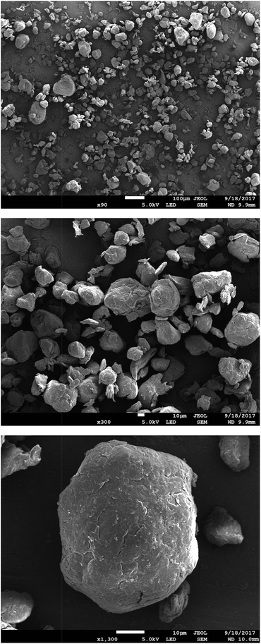
Fig. 4 presents SEM micrographs of the VBC-grafted ETFE powder before it was reacted with the amines. The powder particles show irregular morphology with particle diameters generally in the range 20–50 μm. The precursor ETFE powder particles range from 20–30 μm.31 This shows that grafting did not have an excessive effect on powder particle sizes. On amination with TMA (and subsequent ball milling) the inhomogeneity in particle shape and size (ranging 10–70 μm) increases as shown in Fig. 5. Large inhomogeneities were also observed for AEI(MPY) and AEI(MPRD) (Fig. S2 in the ESI†).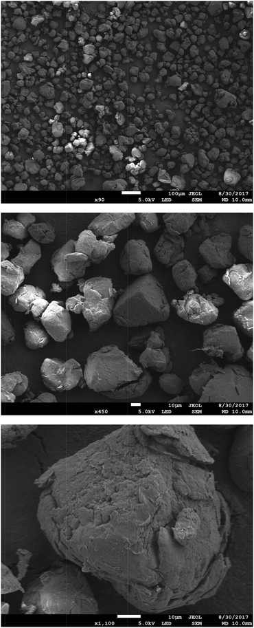 | ||
| Fig. 4 SEM micrographs of the (pre-aminated) VBC-grafted ETFE powders at ×90, ×450, and ×1100 magnifications (from top to bottom). | ||
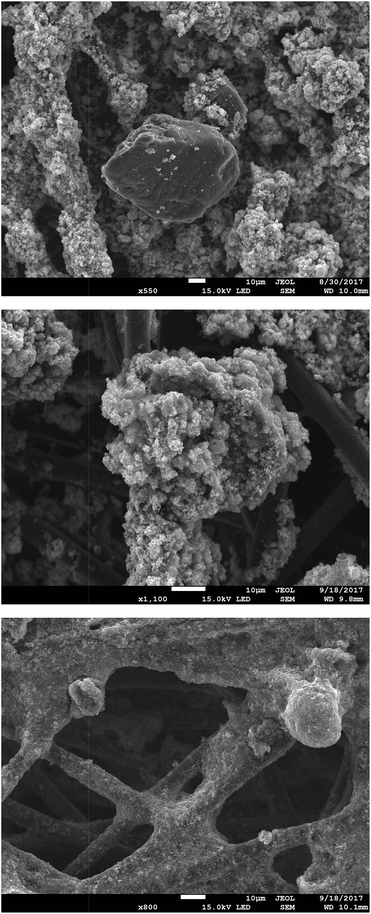
The powder AEIs were incorporated into cathodes (containing Pt/C electrocatalyst) and anodes (containing PtRu/C). 20% wt ionomer was used in the AEI(TMA) electrodes, while 30% wt ionomer was used with AEI(MPY) and AEI(MPRD). These loadings were from AEMFC test optimisation studies (see later). SEM micrographs of sample areas of an electrode of each type are presented in Fig. 6 (for AEI(TMA)) and Fig. S3 in the ESI† (for all powder AEIs). As the powder AEIs are μm-sized but the electrocatalysts are nanoparticles (<100 nm in size) these micrographs cannot give much of a visual indication of the exact morphology of the Pt and PtRu electrocatalyst particles. However, the AEI particles clearly form a denser coverage with the AEI(MPY)- and AEI(MPRD)-containing electrodes (due to the higher ionomer loadings used). A rougher morphology is seen for the PtRu/C-containing anodes compared to the Pt/C-containing cathodes (with all three AEIs). As no microporous layer (MPL) was used (with this class of powder AEI, the use of an MPL appears to lead to lower AEMFC performances) the polymer-catalyst agglomerates are attached directly onto the carbon-fibres of the Toray carbon-paper GDL (with a degree of penetration into the GDL).
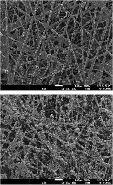 | ||
| Fig. 6 SEM micrographs (×85 magnification) of an exemplar Pt/C cathode (top) and PtRu/C anode (bottom) containing AEM(TMA) at a loading of 20% wt. | ||
On closer inspection, there is evidence of both the Pt/C and PtRu/C catalysts coating the AEI particles and the carbon-fibres of the Toray paper electrodes (Fig. 7 shows some higher magnification SEM micrographs of sample areas of AEI(MPY) containing electrodes). There is also evidence of a proportion of AEI particles (and carbon-fibres) that are not coated with electrocatalyst. Fig. S4–S6 (in the ESI†) show the EDX analysis of different regions on several exemplar electrodes. This EDX analysis confirms that the electrodes contain a poor distribution of C (from the Toray paper and the carbon-support of the electrocatalysts), F (from the AEI), and metals (Pt and Ru).
The morphology of these AEMFC electrodes is clearly different to that found in PEMFC based electrodes, which contain uniform distributions of ionomer and electrocatalyst.32 However, numerous studies have proven that these AEMFC electrodes (containing TMA-based radiation-grafted powder AEIs) can produce high AEMFC power performances.11,25–27,29,33
AEMFC test data (repeatability)
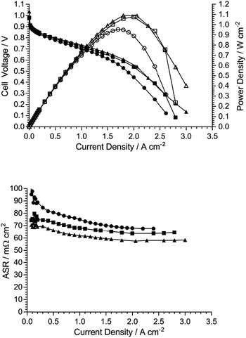
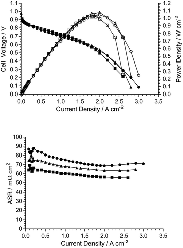
As the electrodes are hand sprayed, and before investigation of the effect of the different quaternary ammonium chemistries, initial experiments were conducted to evaluate the repeatability of electrode preparation. Two types of repeatability tests were conducted: (1) Fig. 8 shows the AEMFC fuel cell performances of three repeat MEAs fabricated using the same TMA-based AEM and powder AEI (from a single batch), and (2) Fig. 9 shows the AEMFC fuel cell performances of three MEAs fabricated using the same TMA-based AEM and three different batches of powder AEIs fabricated using the same synthetic protocol.As can be seen from this data, there is a small amount of variation in peak power density: mean = 1.04 W cm−2 and sample standard deviation = 0.05 W cm−2 (range = 0.95–1.09 W cm−2) across the n = 5 tests conducted (one of the performance curves in Fig. 9 is common with a curve in Fig. 8). As expected, due to the hand fabrication nature of the MEAs, the main differences in performance were due to variances in mass-transport limitations (in the high current density region); variances in electrocatalytic performances (low current density region) and ohmic losses (medium current density region) were less significant. Considering the above, and to aid the relative comparison of AEM/AEI chemistries in AEMFC performance tests (discussed in the next section), the criterion used for the purpose of this study was that MEAs were deemed to have varied in AEMFC performance if their peak power performances were different by >0.10 W cm−2.
AEMFC test data (chemistries)
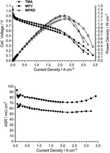
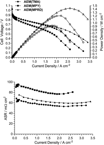
Fig. 10 presents AEMFC test data with three different MEAs where the AEI and AEM in each MEA contain the same quaternary ammonium chemistry (e.g. an MEA containing AEI(TMA) in both electrodes along with AEM(TMA)). It is clear that changing the quaternary ammonium chemistry did not lead to significant differences in AEMFC performance with the use of MEAs in this configuration (containing only one quaternary ammonium chemistry per MEA). Note that 30% wt of ionomer was used with the AEI(MPY)- and AEI(MPRD)-containing MEAs, while 20% wt ionomer was used with the AEI(TMA)-containing MEA, in response to initial studies of AEI loading with each chemistry (Fig. S7–S9 in the ESI†). These loadings are used throughout the rest of this study.Subsequent experiments involved the comparison of electrodes fabricating using each AEI in MEAs containing the different AEMs. Note this study only considers MEAs that contain the same AEI in each electrode: a study into the use of MEAs containing different AEIs in each electrode is planned for the future. Fig. 11 shows the data collected with MEAs containing AEI(TMA)-based electrodes. The variances in peak power densities are large with the use of the different AEM chemistries. The MEA containing AEM(MPRD) yielded the highest power density (of this entire study): 1.43 W cm−2 (at 2.6 A cm−2, ASR = 60 mΩ cm2). The differences in performances were primarily due to differences in in situ ohmic losses and mass transport losses. Considering that AEM(MPRD) had the lowest ex situ conductivity, this result is surprising; this highlights the importance of recording in situ performances in AEMFC tests, which suggest, here, that AEM(MPRD) has faster water transport characteristics that lower mass transport losses.
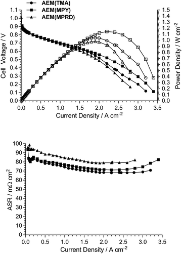
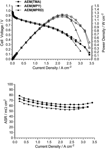
Fig. 12 and 13 show the analogous AEMFC test data using electrodes containing AEI(MPY) and AEI(MPRD), respectively. The relative differences in performances with the three different AEM chemistries is less clear cut when using these cyclic-quaternary-ammonium-based powder AEIs (peak power densities ranged from 0.99 to 1.25 W cm−2 over the n = 6 experiments presented). The performance variations were again primarily due to differences in mass transport losses. The most interesting (take home) finding was that the AEI(MPRD)-based electrodes were particularly insensitive to the AEM chemistry used and produced the highest peak power densities of the cyclic-quaternary ammonium-based AEIs.
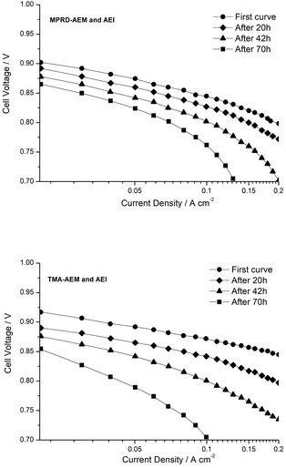
Fig. 14 shows quasi-Tafel-plots (extracted from the data presented in Fig. 11–13), comparing the fuel cells responses for each AEM combined with each AEI. These results show that the Tafel lines are all generally parallel indicating that Tafel slopes do not significantly vary with AEI chemistry (with the same catalysts used in all cases). This implies that the reaction mechanisms and rate determining steps (for both the hydrogen oxidation reaction on PtRu/C and the oxygen reduction reaction on Pt/C) are not being affected by the different AEI chemistries in any major way. This behaviour is consistent with the high local OH− anion concentration in both the anode and cathode environments that may surpass any specific activity effects due to the AEI chemistry. However, the consistently high cell potentials observed with the use of AEI(MPRD) in the electrodes indicates that this AEI generally leads to better electrocatalysis; this could either be due to an enhanced number of active sites or an increase in exchange current densities for one or both reactions.
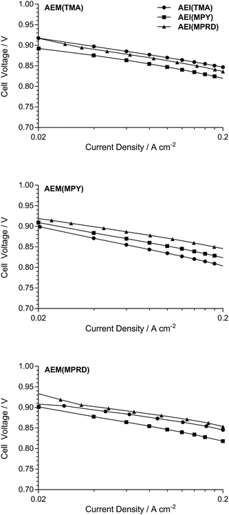 | ||
| Fig. 14 Cell potential vs. log10(current density) plots for the data extracted from Fig. 11–13 between 0.02 and 0.2 A cm−2. | ||
Initial in situ, short-term stability testing
The ex situ alkali stability tests for TMA-, MPY- and MPRD-AEMs have been reported previously.30 Due to the higher hydration levels related to the MPY and MPRD head-group chemistries, these exhibited higher alkali stabilities compared to the benchmark TMA chemistry (e.g. 17–18% loss in IEC when treated in aqueous KOH (1 mol dm−3) for 28 d at 80 °C compared to 30% loss for the TMA-based AEM).However, besides leading to promising fuel cell performances, MPRD-based polymer electrolytes need to be more stable under operando conditions. As an initial move towards this, we conducted comparative, short-term AEMFC tests with the TMA- and MPRD-based MEAs (each MEA contained the same chemistry in all polymer electrolyte components). Fig. 15 presents the quasi-Tafel plots for these two fuel cells: data was collected immediately after cell start up, and then after 20, 42 and 70 h of AEMFC discharge at 0.7 V and at 60 °C (88% and 92% RH for the H2 anode and the O2 cathode respectively).
In all cases the low current density (catalyst activation) region showed a decay in performance as a function of AEMFC discharge time, which relates to a loss of catalyst activity or electrochemical active area (ECSA). For the MPRD-MEA (Fig. 15a), this loss was ca. 37 mV between the initial performance and that observed after 70 h of cell discharge: in contrast this loss was 70 mV for the TMA-MEA (Fig. 15b). Large changes in ECSA have recently been reported for a Pt/C catalyst in aqueous NaOH (0.1 mol dm−3) alkaline electrolyte during accelerated cyclic voltammetric stress tests at 25 °C:34 after 150 cycles (100 mV s−1, between 0.1 to 1.23 V, total test duration of 1 h) a loss of 60% ECSA was observed. This prior observation indicates that catalyst degradations contribute towards the changes in performances reported in Fig. 15, which highlights the need to develop catalysts with stabilities tailored towards operation in AEMFCs.
After several days of AEMFC discharge time, the quasi-Tafel plots tended to curve down at higher current densities (but still at current densities that are below those that cause diffusion limitations): this is characteristic of an increase in ohmic losses, which may be due to a combination of detachment of catalyst from the C-supports,34 and degradation of the anion-exchange polymer electrolyte components. Several prior works have stressed the difficulties in achieving optimized water balance in AEMFCs;25,35–37 the drying out of part of the MEAs in AEMFCs risks AEM/AEI degradation. The use of AEM(MPRD), as already discussed, facilitates better water management and consequently the rate of ohmic resistance increase would be expected to be lower than with the use of AEM(TMA), which is observed in the data presented in Fig. 15.
Overall, the operando voltage decays observed in Fig. 15 cannot be wholly attributed to AEI or AEM degradation. This scenario further highlights that more effort is required to determine the predominant source of operando stability. Considering issues with accessing test equipment and the length of time that such experiments take, such testing can only be rigorously conducted once suitable AEI-AEM combinations are identified. The results reported in this study represent the first step towards achieving this.
Conclusions and future directions
This study involved the development of ETFE-based radiation-grafted anion-exchange ionomer (AEI) powders containing different head-group chemistries made using trimethylamine (TMA), N-methylpyrrolidine (MPY), and N-methylpiperidine (MPRD) amination agents. These AEIs were used to form membrane electrode assemblies (MEA) containing anion-exchange membranes (AEM) with the same chemistries. The resulting anion-exchange membrane fuel cell (AEMFC) performance tests on these MEAs showed that all the head-group chemistries yielded excellent AEMFC performances at 60 °C. The key finding of this study was that the MPRD-based materials showed particularly notable characteristics related to the power outputs of the AEMFCs.Our previous study on ETFE-based radiation-grafted AEMs containing the TMA-, MPY-, and MPRD-based chemistries showed that MPRD-containing (and MPY-containing) materials have higher alkali stabilities (when hydrated) compared to TMA-based materials.30 The combination of this prior finding with the AEMFC findings in this study strongly suggests that further detailed investigation of MPRD-based radiation-grafted AEMs and AEIs is warranted. However, as recently discovered (subsequent experiments that were chronologically conducted after those presented in this paper), replacing the ETFE-based AEMs with LDPE-AEMs leads to more mechanically robust AEMs (it is the mechanical weakness of the ETFE-based AEMs that limits AEMFC testing to 60 °C).38 We are now investigating the use of these powder AEIs in combination with LDPE-based AEMs (including MPRD versions); now that the highest performing AEI- and AEM-chemistry has been identified, these studies involving the more robust LDPE-based AEMs will include in situ durability testing at 80 °C (not achievable with ETFE-based AEMs).
Author contributions
Most of the test results were collected by ALGB, who also synthesised and characterised AEI(TMA) and AEI(MPY), with assistance from EIS (whose preliminary experiments on AEI synthesis and loadings guided this study). The MPRD-based materials were synthesised and characterised by DH. AEM(TMA) and AEM(MPY) materials were produced and characterised by LQW and RBS, respectively. EAT assisted with the data collection and analyse for Fig. 14 and 15. The choice of head-group chemistry was directed by JPG's work and guidance. GS's results were essential in justifying the use of the radiation-grafted method for this study (Fig. S1†). All other authors made contributions towards project direction, data analysis and manuscript preparation. JRV was responsible for overall project supervision and made a substantial contribution towards the drafting of the article.Conflicts of interest
There are no conflicts to declare.Acknowledgements
The research was funded by the Engineering and Physical Sciences Research Council (EPSRC grants EP/M014371/1, EP/M022749/1, and EP/M005933/1). ALGB's exchange was funded by FAPESP grants 2016/13277-9 and 2015/09210-3, while EIS' exchange was funded by FAPESP grants 2015/23621-6, 2014/09087-4 and 2014/50279-4. DH's student-exchange was funded by a PDIF Short Stay Scholarship of the Autonomous University of Madrid. GS' 2015 exchange was funded by the ERASMUS+ work placement scheme.References
- P. P. Kundu, V. Sharma and Y. G. Shul, Crit. Rev. Solid State Mater. Sci., 2007, 32, 51–66 CrossRef CAS
.
- Z. P. Cano, D. Banham, S. Ye, A. Hintennach, J. Lu, M. Fowler and Z. Chen, Nat. Energy, 2018, 3, 279–289 CrossRef
.
-
Fuel Cell Systems Explained, ed. J. Larmine and A. Dick, 2nd edn, John Wiley & Sons, 2003 Search PubMed
.
- T. Zhou, R. Shao, S. Chen, X. He, J. Qiao and J. Zhang, J. Power Sources, 2015, 293, 946–975 CrossRef CAS
.
- A. Brouzgou, A. Podias and P. Tsiakaras, J. Appl. Electrochem., 2013, 43, 119–136 CrossRef CAS
.
- J. Pan, C. Chen, L. Zhuang and J. Lu, Acc. Chem. Res., 2012, 45, 473–481 CrossRef CAS PubMed
.
- B. Gupta and G. Scherer, Chimia, 1994, 48, 127–137 CAS
.
- U. Lappan, U. Geiβler, U. Gohs and S. Uhlmann, Macromolecules Materials and Engineering, 2009, 294, 510–515 CrossRef CAS
.
- M. Mamlouk, J. A. Horsfall, C. Williams and K. Scott, Int. J. Hydrogen Energy, 2012, 37, 11912–11920 CrossRef CAS
.
- L. Gubler, Adv. Energy Mater., 2014, 4, 1300827 CrossRef
.
- L. Wang, J. J. Brink, Y. Liu, A. M. Herring, J. Ponce-González, D. K. Whelligan and J. R. Varcoe, Energy Environ. Sci., 2017, 10, 2154–2167 RSC
.
- X. Gao, H. Yu, J. Jia, J. Hao, F. Xie, J. Chi, B. Qin, L. Fu, W. Song and Z. Shao, RSC Adv., 2017, 7, 19153–19161 RSC
.
- J. R. Varcoe, R. C. T. Slade and E. Lam How Yee, Chem. Commun., 2006, 1428–1429 RSC
.
- D. Yang, H. Yu, G. Li, Y. Zhao, Y. Liu, C. Zhang, W. Song and Z. Shao, J. Power Sources, 2014, 267, 39–47 CrossRef CAS
.
- J. R. Varcoe, P. Atanassov, D. R. Dekel, A. M. Herring, M. A. Hickner, P. A. Kohl, A. R. Kucernak, W. E. Mustain, K. Nijmeijer, K. Scott, T. Xu and L. Zhuang, Energy Environ. Sci., 2014, 7, 3135–3191 RSC
.
- S. Gu, R. Cai, T. Luo, Z. Chen, M. Sun, Y. Liu, G. He and Y. Yan, Angew. Chem., Int. Ed., 2009, 48, 6499–6502 CrossRef CAS PubMed
.
- J. Pan, C. Chen, L. Zhuang and J. Lu, Acc. Chem. Res., 2012, 45, 473–481 CrossRef CAS PubMed
.
- J. Pan, S. Lu, Y. Li, A. Huang, L. Zhuang and J. Lu, Adv. Funct. Mater., 2010, 20, 312–319 CrossRef CAS
.
- L. Zeng and T. S. Zhao, Electrochem. Commun., 2012, 34, 278–281 CrossRef
.
- L. Zeng, T. S. Zhao, L. An, G. Zhao, H. X. Yan and C. Y. Jung, J. Power Sources, 2015, 275, 506–515 CrossRef CAS
.
- M. S. Shin, Y. J. Byun, Y. W. Choi, M. S. Kang and J. S. Park, Int. J. Hydrogen Energy, 2014, 39, 16556–16561 CrossRef CAS
.
- Y. Leng, L. Wang, M. A. Hickner and C. Y. Wang, Electrochim. Acta, 2015, 152, 93–100 CrossRef CAS
.
- L. Sun, J. Guo, J. Zhou, Q. Xu, D. Chu and R. Chen, J. Power Sources, 2012, 202, 70–77 CrossRef CAS
.
- S. D. Poynton, R. C. T. Slade, T. J. Omasta, W. E. Mustain, R. Escudero-Cid, P. Ocón and J. R. Varcoe, J. Mater. Chem. A, 2014, 2, 5124–5130 RSC
.
- T. J. Omasta, L. Wang, X. Peng, C. A. Lewis, J. R. Varcoe and W. E. Mustain, J. Power Sources, 2018, 375, 205–213 CrossRef CAS
.
- T. J. Omasta, A. M. Park, J. M. LaManna, Y. Zhang, X. Peng, L. Wang, D. L. Jacobson, J. R. Varcoe, D. S. Hussey, B. S. Pivovar and W. E. Mustain, Energy Environ. Sci., 2018, 11, 551–558 RSC
.
- L. Wang, J. J. Brink and J. R. Varcoe, Chem. Commun., 2017, 53, 11771–11773 RSC
.
- J. Ponce-González, I. Ouachan, J. R. Varcoe and D. K. Whelligan, J. Mater. Chem. A, 2018, 6, 823–827 RSC
.
- L. Wang, E. Magliocca, E. L. Cunningham, W. E. Mustain, S. D. Poynton, R. Escudero-Cid, M. M. Nasef, J. Ponce-González, R. Bance-Souahli, R. C. T. Slade, D. K. Whelligan and J. R. Varcoe, Green Chem., 2017, 19, 831–843 RSC
.
- J. Ponce-Gonzalez, D. K. Whelligan, L. Wang, R. Bance-Soualhi, Y. Wang, Y. Peng, H. Peng, D. C. Apperley, H. N. Sarode, T. P. Pandey, A. G. Divekar, S. Seifert, A. M. Herring, L. Zhuang and J. R. Varcoe, Energy Environ. Sci., 2016, 9, 3724–3735 RSC
.
- www.agcce.com/brochurespdfs/sales/FluonGrades.pdf, accessed 2018-08-14.
- S. J. Normile, D. C. Sabarirajan, O. Calzada, V. de Andrade, X. Xiao, P. Mandal, D. Y. Parkinson, A. Serov, P. Atanassov and I. V. Zenyuk, Materials Today Energy, 2018, 9, 187–197 CrossRef
.
- L. Wang, M. Bellini, H. A. Miller and J. R. Varcoe, J. Mater. Chem. A, 2018, 6, 15404–15412 RSC
.
- A. Zadick, L. Dubau, N. Sergent, G. Berthoméand and M. Chatenet, ACS Catal., 2015, 5, 4819–4824 CrossRef CAS
.
- A. Serov, I. V. Zenyuk, C. G. Arges and M. Chatenet, J. Power Sources, 2018, 375, 149–157 CrossRef CAS
.
- S. Gottesfeld, D. R. Dekel, M. Page, C. Bae, Y. Yan, P. Zelenay and Y. S. Kim, J. Power Sources, 2018, 375, 170–184 CrossRef CAS
.
- D. R. Dekel, S. Willdorf, U. Ash, M. Amar, S. Pusara, S. Dhara, S. Srebnik and C. E. Diesendruck, J. Power Sources, 2018, 375, 351–360 CrossRef CAS
.
- L. Wang, J. J. Brink, Y. Liu, A. M. Herring, J. Ponce-Gonzalez, D. K. Whelligan and J. R. Varcoe, Energy Environ. Sci., 2017, 10, 2154–2167 RSC
.
Footnote |
| † Electronic supplementary information (ESI) available: Additional SEM, EDX and fuel cell data in support of the main article. See DOI: 10.1039/c8ta08309f |
| This journal is © The Royal Society of Chemistry 2018 |

