
 Open Access Article
 This Open Access Article is licensed under a
 Creative Commons Attribution 3.0 Unported Licence
Solvent mediated morphology control of zinc MOFs as carbon templates for application in supercapacitors†
Jongkook
Hwang
 ,
Runyu
Yan
,
Martin
Oschatz
and
Bernhard V. K. J.
Schmidt
*
,
Runyu
Yan
,
Martin
Oschatz
and
Bernhard V. K. J.
Schmidt
*
Department of Colloid Chemistry, Max-Planck Institute of Colloids and Interfaces, Am Mühlenberg 1, 14476 Potsdam, Germany. E-mail: Bernhard.schmidt@mpikg.mpg.de
First published on 23rd October 2018
Abstract
While downscaling metal–organic frameworks (MOFs) into a nanosize regime is highly relevant to meet their growing demand in various potential applications, a simple synthesis of nano-MOF under ambient conditions still remains a difficult task. Here we report a room temperature synthesis of 3D MOF, [Zn2(bdc)2dabco]n (ZBD) (bdc = benzene-1,4-dicarboxylic acid and dabco = 1,4-diazabicyclo[2.2.2]octane) with controlled polymorphism, size, and morphology by changing the kind and composition of solvents. The solvents function as both templates and crystal modulators. Dimethylformamide (DMF) preferably forms a hexagonal rod MOF (ZBDh) while methanol (MeOH) leads to the formation of a tetragonal plate MOF (ZBDt) via a solvent template effect (i.e., polymorph control). The size and morphology can be further controlled using DMF and MeOH as cosolvents with various volume ratios. DMF and MeOH work competitively, and the solvent with a weaker template effect under the given conditions acts as a crystal modulator that lowers the rate of nucleation and increases the size of the crystals. With an increase of MeOH amount, the morphology changes from 1D rods to 2D plates. Protic MeOH reduces the reactivity of nucleophilic dabco and suppresses crystal growth along Zn-dabco [001], thereby leading to the formation of 2D ZBDt plates. To help understand the fundamental morphology–volumetric capacitance relationships in energy storage devices, the resulting ZBDs are conformally pyrolyzed to hexagonal rod- and tetragonal plate-nanoporous carbons and used as electrodes for supercapacitors. Thanks to a 2D morphology and relatively high packing density, tetragonal plate carbon delivers two times higher volumetric capacitance than hexagonal rod carbon, despite their nearly similar gravimetric capacitances.
Introduction
Metal–organic frameworks (MOFs) are a class of crystalline porous materials that are constructed using organic linkers and inorganic metal nodes.1 Because of their high degree of chemical and structural tunability at a molecular level, MOFs have attracted significant attention as versatile materials for a plethora of applications such as gas storage/separation, sensors, catalysis and energy storage devices.2–5 Furthermore, MOFs have recently emerged as new precursors/sacrificial templates for the preparation of functional porous carbon and carbon based metal/metal oxide composites that may not be easily synthesized by conventional synthesis routes.6–10To meet the ever-growing demand of MOFs in a myriad of potential applications, considerable research efforts have been devoted to controlling the size and morphology of MOFs in a nanosize regime, which can tailor the physical/chemical properties without changing the chemical compositions.11,12 Structuring MOFs at the nano- and mesoscopic scale has been accomplished by various methodologies11–13 such as microwave assisted synthesis,14 mechanochemical synthesis,15 interfacial assembly,16,17 emulsion templating,18 and coordination modulation.19,20 However, these approaches usually require specific reactors and equipment, or additional additives and modulators that are sometimes restricted to work in a narrow synthesis parameter window only. In addition, less attention has been paid to control framework topology (i.e., polymorphism), although it can potentially provide new opportunities for controlling the intrinsic properties and morphologies of MOFs. In this regard, development of a simple strategy that simultaneously enables control over the size, morphology, and framework topology of MOFs under ambient synthetic conditions is highly relevant.
The solvent is one of the critical parameters in MOF synthesis, as its properties such as polarity and solubility of the building blocks greatly influence the nucleation and growth of MOFs.11 Thus, the solvent can not only act as a reaction medium but also a structure directing agent that affects the structures and topologies of the final MOFs by a solvent template effect.21,22 Considering the fact that the pores of the as-made MOFs are generally filled with the solvents as guest molecules, the solvent template effect can become an effective means for preparing MOFs with the desired framework topology. To date, a few systematic studies about the solvent effect on MOF formation have been reported,22–26 however, most of the studies are usually MOF specific and limited to polymorph control only, and therefore considerably lack the ability to adjust the particle size and morphology (e.g., aspect ratio). While a simple solvent mediated strategy toward a designable nano-MOF is highly desirable, it still remains largely unexplored due to the lack of efficient solvent systems and incomplete understanding of the associated MOF formation mechanisms.
Electric double-layer capacitors (EDLCs) have aroused tremendous research interest for decades because of their fast charging capabilities, long cycle life, high stability and safe operation.27–30 One of the most important components in such devices is the carbonaceous electrode material as its ability for electrosorption of electrolyte ions is crucial for the specific capacitance and thus the energy density.31,32 A wide variety of novel carbonaceous materials such as activated carbon,33 carbide-derived carbon,34 zeolite-templated carbon,35 carbon nanotubes,36 and graphene37 have been extensively investigated as electrodes in EDLCs. The capacitance of carbon-based electrode materials and supercapacitors in general has been effectively enhanced by (i) increasing the specific surface area and tailoring the pore size and distribution,32,38,39 (ii) producing composites with pseudocapacitive materials (e.g., metal oxides and conductive polymers),40 and (iii) doping with heteroatoms or incorporating functional moieties.41
Recently, volumetric performance has become a more and more important criterion that gives a realistic picture of the charge-storage capacity in the limited space of energy storage devices, particularly in next generation portable electronic devices and electric vehicles.38,42,43 Although nanoporous carbons provide a stable and reliable performance, they show a relatively low volumetric performance due to their inherent low density. This in turn leads to the presence of significant “dead volume” in EDLC electrodes, that is, the electrode volume that has to be filled with the electrolyte but is not used for energy storage. One promising strategy to overcome this limitation is the preparation of carbon particles with controlled size and morphology that can maximize the materials' packing density.42 In this respect, MOF-derived carbons (MDCs) are highly advantageous because a wide variety of inherent crystal morphologies of MOFs can be transferred through pseudomorphic transformation.6–10 Moreover, MDCs can have high surface area, adjustable porosity, and can be doped with heteroatoms without post-treatments. These properties are very attractive for the development of high performance EDLC electrodes. Therefore, morphology controlled MDCs are highly relevant to understanding the fundamental morphology–performance relationships in electrochemical energy storage, which in turn potentially enables the targeted development of electrodes with high volumetric efficiency.
Herein, we report a solvent mediated room temperature synthesis of a 3D MOF, [Zn2(bdc)2dabco]n (ZBD) (bdc= benzene-1,4-dicarboxylic acid and dabco = 1,4-diazabicyclo[2.2.2]octane) with controlled size, morphology and polymorphism by changing the kind and composition of the solvents used (Scheme 1). ZBD is a prototypical dabco MOF having unique guest-dependent framework flexibility and continuous 1D nanochannels,44,45 which are suitable for a broad range of applications such as gas storage, adsorption, separation and controlled polymerization.46–51 Dimethylformamide (DMF) and methanol (MeOH) induce the selective formation of a hexagonal rod MOF with Kagome nets (ZBDh) and a tetragonal plate MOF with square-grid nets (ZBDt), respectively. The size and morphology can be further controlled by using DMF and MeOH with different ratios as a cosolvent, which can tailor the polarity and solubility of the reactants and thus the nucleation and growth of MOFs. Conformal transformation of MOF precursors via carbonization at 900 °C leads to the preparation of hexagonal rod- and tetragonal plate-nanoporous carbon, which are subsequently employed as electrodes for EDLCs. Benefitting from a 2D morphology and a high packing density, tetragonal plate MDC delivers two times higher volumetric capacitance than hexagonal rod MDC, despite their similar gravimetric capacitances. The result highlights the importance of particle morphology for fabrication of high volumetric capacitance EDLC electrodes.
 | ||
| Scheme 1 Solvent mediated synthesis of [Zn2(bdc)2dabco]n (ZBD) with controlled size, morphology and polymorphism. (a) ZBD with a hexagonal framework (ZBDh), (b) ZBD with a tetragonal framework (ZBDt) and their transformation into nanoporous carbon. | ||
Experimental
Materials
Benzene-1,4-dicarboxylic acid (bdc, >99%, Sigma-Aldrich), 1,4-diazabicyclo[2.2.2]octane (dabco, >99%, Sigma-Aldrich), N,N-dimethylformamide (DMF, analytical grade, VWR), methanol (MeOH analytical grade, VWR), and zinc nitrate hexahydrate (Zn(NO3)2·6H2O, 98%, Acros) were used as received.Synthesis of [Zn2(bdc)2dabco]n and its derived carbon
[Zn2(bdc)2dabco]n MOFs with either hexagonal (ZBDh) or tetragonal (ZBDt) framework topology were selectively prepared by using DMF, MeOH or their mixture as a solvent. ZBDh-DxMy denotes [Zn2(bdc)2dabco]n with hexagonal topology prepared in a cosolvent of DMF x![[thin space (1/6-em)]](https://www.rsc.org/images/entities/char_2009.gif) :MeOH y, wherein x and y represent the volume ratio of each solvent (x + y = 10). In a typical synthesis of ZBDh-D10, three solutions of bdc (1.20 mmol, 200 mg in 250 mL DMF), Zn(NO3)2·6H2O (1.20 mmol, 227 mg in DMF 25 mL), and dabco (0.60 mmol, 67.3 mg in DMF 25 mL) were prepared separately. The Zn and dabco solutions were added to the bdc solution in sequence under stirring for 10 min. The mixture remained for 48 h without stirring. The solid was collected by centrifugation, washed with DMF 3 times, and dried under vacuum at 85 °C. For the synthesis of ZBDt-M10, MeOH was solely used instead of DMF. For the synthesis of ZBDh(t)-DxMy, the cosolvent of DMF and MeOH with various volume ratios was used, while the concentration of the reactants was kept constant. The other procedures were the same as those described in ZBDh-D10 synthesis. The resulting MOFs were carbonized at 900 °C for 2 h under Ar flow in a horizontal tubular furnace with a heating rate of 5 °C min−1, and used as electrodes in EDLCs without further treatment.
:MeOH y, wherein x and y represent the volume ratio of each solvent (x + y = 10). In a typical synthesis of ZBDh-D10, three solutions of bdc (1.20 mmol, 200 mg in 250 mL DMF), Zn(NO3)2·6H2O (1.20 mmol, 227 mg in DMF 25 mL), and dabco (0.60 mmol, 67.3 mg in DMF 25 mL) were prepared separately. The Zn and dabco solutions were added to the bdc solution in sequence under stirring for 10 min. The mixture remained for 48 h without stirring. The solid was collected by centrifugation, washed with DMF 3 times, and dried under vacuum at 85 °C. For the synthesis of ZBDt-M10, MeOH was solely used instead of DMF. For the synthesis of ZBDh(t)-DxMy, the cosolvent of DMF and MeOH with various volume ratios was used, while the concentration of the reactants was kept constant. The other procedures were the same as those described in ZBDh-D10 synthesis. The resulting MOFs were carbonized at 900 °C for 2 h under Ar flow in a horizontal tubular furnace with a heating rate of 5 °C min−1, and used as electrodes in EDLCs without further treatment.
Materials characterization
The crystal structure was confirmed using a powder X-ray diffractometer (PXRD) with Cu-Kα radiation (λ = 0.154 nm) and a scintillation counter (KeveX Detector). Nitrogen adsorption and desorption experiments were performed using a Quantachrome Quadrasorb apparatus at 77 K. The samples were degassed at 150 °C for 20 h before the measurements. The isotherms were analyzed using QuadraWin software (version 5.05). The surface area was determined by the Brunauer–Emmett–Teller (BET) method using the multipoint BET model (P/P0 = 0.005–0.075 for MOF, P/P0 = 0.05–0.2 for MDC). The pore size distributions of the MOF were calculated by a slit pore nonlocal density functional theory (NLDFT) equilibrium model for N2 adsorbed on silica. The pore size distributions of MDC were calculated by using a slit/cylindrical pore quenched solid density functional theory (QSDFT) equilibrium model (adsorption branch kernel) for N2 adsorbed on carbon. Scanning electron microscopy (SEM) (LEO 1550-Gemini microscope) and transmission electron microscopy (TEM) (EM 912 Omega/Carl-Zeiss Oberkochen) operating at 120 kV were used to investigate particle morphologies and pore structures. Inductively coupled plasma-optical emission spectrometry (ICP-OES) was conducted using a PerkinElmer Optima 8000 instrument, calibrated with standard solutions. Raman spectra were recorded using a Witec Raman microscope operating at an excitation wavelength of 532 nm with a power of 4.0 mW. Thermogravimetric analysis (TGA) was conducted with a Netzsch TG 209 F1 device under constant artificial air flow in platinum pans at a heating rate of 10 °C min−1 to 1000 °C. Elemental analysis was performed with a vario MICRO cube CHNOS Elemental Analyzer in the CHNS mode. X-ray photoelectron spectroscopy (XPS) measurements were performed using a Thermo Scientific K-Alpha+ X-ray photoelectron spectrometer.Fabrication of EDLCs and electrochemical measurements
To prepare free-standing electrodes for EDLCs, carbonized MOFs and polytetrafluoroethylene (PTFE, 60 wt% solution in H2O from Sigma Aldrich) were mixed with a mass ratio of ∼9:1 in ethanol. The solution was then transferred to a glass plate and mixed with razor blades until it changed to a rubber-like consistency. Then it was placed on aluminum foil and rolled into uniformly thin sheets with similar thicknesses of ∼200 μm using a commercial roll mill, followed by punching into free-standing electrode disks of 10 mm in diameter. The mass loading of ZBDh-D10-900 and ZBDt-M10-900 was determined to be 5.6 and 10.4 mg cm−2, respectively. The electrodes were dried at 60 °C for 12 h in air. EDLCs were tested in a symmetrical two-electrode configuration employing the common organic electrolyte 1 M tetraethylammonium tetrafluoroborate/acetonitrile (TEABF4/AN). A Swagelok cell was assembled using a pair of circular electrodes sandwiching a 25 μm trilayer polypropylene–polyethylene–polypropylene membrane (Celgard 2325, 13 mm in diameter), with 60 μL electrolyte and two platinum foils as current collectors. The EDLCs were assembled in an Ar filled glove box (H2O < 0.1 ppm, O2 < 0.1 ppm). A Biologic MPG-2 galvanostat/potentiostat was used for electrochemical characterization. All measurements were performed at room temperature. Electrochemical impedance spectroscopy was performed at open circuit potential with a sinusoidal signal over a frequency range from 20 kHz to 10−2 Hz at an amplitude of 10 mV.
Cyclic voltammetry (CV) tests were performed at a cell voltage of 0–2.5 V and at scan rates of 10–500 mV s−1. The carbon integral volumetric capacitance, C (F cm−3), was calculated according to the following equation:
 | (1) |
Galvanostatic charge/discharge with potential limitation (GCPL) was applied at specific currents between 0.1 and 10 A g−1 in a voltage range from 0 to 2.5 V.
For long-term stability tests, the voltage of the cell was kept at 2.5 V for 100 h, and the specific capacity was measured every 10 h by galvanostatic cycling at 1 A g−1.
Results and discussion
Conventional synthesis of ZBD
Because of the flexible nature of the bdc ligand, ZBD has two polymorphs, either a hexagonal framework with 2D Zn-bdc Kagome layers (ZBDh)52 or a tetragonal framework with 2D Zn-bdc square-grid layers (ZBDt),44 which are connected by dabco pillars to form a 3D structure (Scheme 1; Fig. S1†). Previous research studies reveal that ZBDh is the metastable kinetic phase and ZBDt is the thermodynamically stable phase.20,53,54 In a typical solvothermal synthesis in DMF at 120 °C, ZBDh is first formed at the early stages of the reaction but subsequently undergoes dissolution and recrystallization to thermodynamic ZBDt upon prolonging the reaction.53 Thus, a ZBDt single crystal can be obtained only after solvothermal reaction for 48 h.44 Because of this complex crystallization process, the synthesis of nano-ZBDt with controlled size has never been achieved yet. Likewise, although ZBDh is relatively easy to access via solvothermal- and mechanochemical methods,15,52,54 its size and morphology are difficult to control because of its inherent metastability. Taken together, selective synthesis of nano-ZBDh and -ZBDt with adjustable size and morphology is yet to be realized.Selective and controllable synthesis of ZBD at room temperature
The solvent effect was studied by using DMF, MeOH and their mixture with various DMF:MeOH volume ratios (Fig. 1). The resulting products are labelled ZBDh(t)-DxMy, wherein x and y represent the volume ratio of each solvent (x + y = 10). The reactants (Zn(NO3)2·6H2O, bdc, and dabco) were separately dissolved in a target solvent, and mixed under stirring. The solution became turbid right after the mixing, and remained under static conditions for 48 h. The white precipitates were collected, washed, and dried under vacuum at 85 °C.
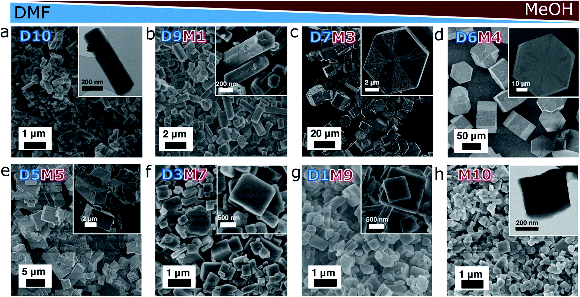 | ||
| Fig. 1 SEM and TEM images of ZBDh(t)-DxMy, wherein h and t represent hexagonal and tetragonal frameworks, and x and y represent the volume ratios of DMFx:MeOHy (x + y = 10). (a) ZBDh-D10, (b) ZBDh-D9M1, (c) ZBDh-D7M3, (d) ZBDh-D6M4, (e) ZBDt-D5M5, (f) ZBDt-D3M7, (g) ZBDt-D1M9, and (h) ZBDt-M10. | ||
The morphologies of the as-synthesized ZBDh(t)-DxMy were investigated by electron microscopy (Fig. 1). ZBDh-D10 has an anisotropic hexagonal 1D rod-like morphology with hundreds of nanometers in length (Fig. 1a). As the volume ratio of MeOH increased from D10 to D9M1 to D7M3 to D6M4, the particle size increased from 0.58 to 1.2 to 13 to 75 μm (Fig. 1a–d), accompanied by morphology changes from nanorods to microplates. Hexagonal faces along the [001] direction were clearly observable in SEM. An intermediate mixture of both morphologies was observed in a narrow window of reaction conditions, e.g., D5.5M4.5 (Fig. S2†). Further increase in MeOH fraction ≥50vol% (i.e., 66 mol%) led to crystal phase transition from hexagonal to tetragonal framework topology. With an increase of MeOH ratio from D5M5 to D3M7 to D1M9 to M10, the particle size decreased from 3.4 to 0.72 to 0.65 to 0.43 μm (Fig. 1e–h), and the morphology changed from cubic microparticles to 2D-like cubic nanoplates. The changes in particle size and aspect ratio of ZBDh(t)-DxMy are summarized in Table S1 and Fig. S3.†
The selective formation of ZBDh and ZBDt was further supported by PXRD and N2 physisorption analysis (Fig. 2). PXRD patterns revealed that the synthesized ZBD can be assigned to one of the three classes, which correspond to hexagonal ZBDh-(D10, D9M1, D7M3, D6M4), an intermediate transition phase (D5.5M4.5), and tetragonal ZBDt (D5M5, D3M7, D1M9, M10) (Fig. 2a). The results were further confirmed by N2 physisorption at 77 K and pore size distribution calculated by a slit pore NLDFT equilibrium model. The two polymorphs ZBDh and ZBDt have distinct surface areas and pore sizes, which indicate phase pure ZBD synthesis. In general, ZBDh has a larger surface area and pore size than ZBDt, as calculated from single crystal structure analysis and simple geometric considerations.52 The representative N2 sorption isotherms for ZBDh-D10 and ZBDt-M10 are shown in Fig. 2b. N2 sorption isotherms show abrupt gas uptake and saturation at a very low relative pressure <0.05, which is typical type-I behavior of microporous materials (Fig. 2b and S4†). The BET surface areas of ZBDh and ZBDt were in the range of 1880–2160 m2 g−1 and 1480–1760 m2 g−1, respectively. Such values are comparable to or even larger than those of their bulk counterparts. The pore size distributions also show distinct micropores of ZBDh (1.3–1.8 nm) and ZBDt (1.0–1.2 nm) (Fig. 2c). Note that the estimated pore size from NLDFT is highly dependent on the equilibrium model used and is not as accurate as that from the single crystal analysis, but the characteristic micropores of ZBDh and ZBDt can be distinguished by using the same NLDFT model, which indicates the phase selective synthesis of ZBD. TGA data show that the synthesized ZBDh and ZBDt have thermal stabilities similar to those of the reference materials reported in the literature (Fig. S5†).44,52 They lost the guest solvents at temperatures below 200 °C, and started to decompose at 300 °C. The physicochemical properties of ZBD are summarized in Table S2.†
 | ||
| Fig. 2 Effect of solvent composition on ZBDh(t)-DxMy formation. (a) PXRD patterns. (b) Representative N2 sorption isotherms of ZBDh-D10 and ZBDt-M10 and (c) their pore size distributions. (d) Graph of BET surface area change (i.e., morphology and topology change) with respect to MeOH mole fraction. | ||
All results are in good agreement with the SEM observations and clearly support the successful synthesis of ZBD with controlled polymorphism, size and morphology by simply adjusting the kind and composition of the solvent used for MOF synthesis. It should be mentioned that the synthesis of nanoZBDt with controlled size is reported, to the best of our knowledge, for the first time in the present work.
Solvent effect on ZBD formation
To better present the relationships between solvent composition and ZBD structures, the graph of surface area change (i.e., morphology and topology change) with respect to MeOH mole fraction is illustrated in Fig. 2d, which highlights the abrupt change in morphology with solvent composition.The slight change in the size of the solvent template (guest molecule) can lead to the formation of ZBD with different framework topologies, i.e., the bulkier solvent molecule has bigger steric hindrance and may thus induce the formation of a MOF polymorph with larger pore size. As expected from the bulk density (ZBDh 0.730 vs. ZBDt 0.870 g cm−3) and pore size (ZBDh 1.5 vs. ZBDt 0.75 nm),44,52 bulkier DMF prefers ZBDh and MeOH prefers ZBDt. As confirmed in Fig. 2d and S3,† formation of ZBDh dominates over ZBDt formation in a broad range of MeOH mole fractions (0–0.6). ZBDt could be obtained when a MeOH mole fraction >0.66 was employed. Thus, it can be inferred that DMF has a stronger template effect than MeOH. DMF and MeOH work competitively rather than cooperatively. One overwhelms the other and preferably induces the formation of one particular crystal phase.
The competitive relationship between DMF and MeOH further enables the control over the size of the resulting ZBD crystals. For instance, in the case of ZBDh synthesis in a DMF/MeOH system, MeOH hinders the formation of ZBDh nuclei and decreases the rate of nucleation. Therefore fewer nuclei grow into larger crystals with increasing amount of MeOH (Fig. 2d). Likewise, the size of ZBDt increases with increasing amount of DMF. This phenomenon was further supported experimentally by the time dependent observation of crystal growth of ZBDh-D10 and ZBDh-D6M4. In a pure DMF system (ZBDh-D10) most of the ZBDh nuclei were rapidly generated and grew/saturated to a few hundred nanometer-sized crystals after reaction for 5 h, which suggests a fast and homogeneous nucleation at the early stage of the reaction (Fig. S6†). In contrast, in ZBDh-D6M4, the nucleation was largely retarded by MeOH, and therefore the secondary heterogeneous nucleation occurred continuously (Fig. S7†). The newly generated nuclei/small nanocrystals and large crystals existed together even after reaction for 32 h (Fig. S7a–f†). With increasing reaction time, the initially formed nuclei grew into large crystals at the expense of small nanocrystals via Ostwald ripening, leading to the formation of pure hexagonal microplates after reaction for >48 h (Fig. S7g and h†).
The particle morphology (e.g., aspect ratio) is also greatly affected by solvent composition (Table S1; Fig. S3†). As the amount of MeOH increased, the anisotropic hexagonal nanorods (ZBDh-D10) transformed into hexagonal microplates (ZBDh-D6M4) to tetragonal microcubes (ZBDt-D5M5) to 2D-like tetragonal nanoplates (ZBDt-M10) (Fig. 1 and 2d). This unique morphology evolution can be understood by the intrinsic crystal growth modes of ZBD and the polar protic nature of MeOH. ZBD has two growth modes (Zn-bdc and Zn-dabco) (Fig. S1†). Zn-bdc forms 2D hexagonal or tetragonal layers which are three dimensionally extended by dabco pillars. As a result, ZBDh consists of two hexagonal (001) faces terminated by Zn-dabco bonds and the other six faces terminated by Zn-bdc bonds (Scheme 2). The relatively high energy Zn-dabco (001) surfaces disappear through preferential anisotropic growth along the [001] direction in ZBDh-D10.20 However, such Zn-dabco growth can be largely suppressed by addition of polar protic MeOH, which can form hydrogen bonds with the nucleophilic dabco ligand, creating a shell of MeOH molecules around dabco (Scheme 2).55 The lone pair electrons of dabco possibly interact with the electron-poor hydrogen atoms of MeOH. As a result, polar protic MeOH can decrease the reactivity of dabco and hinder the growth of Zn-dabco (001) surfaces, whereas polar aprotic DMF cannot, thereby resulting in the formation of 2D-like nanoplates of ZBDt-M10.
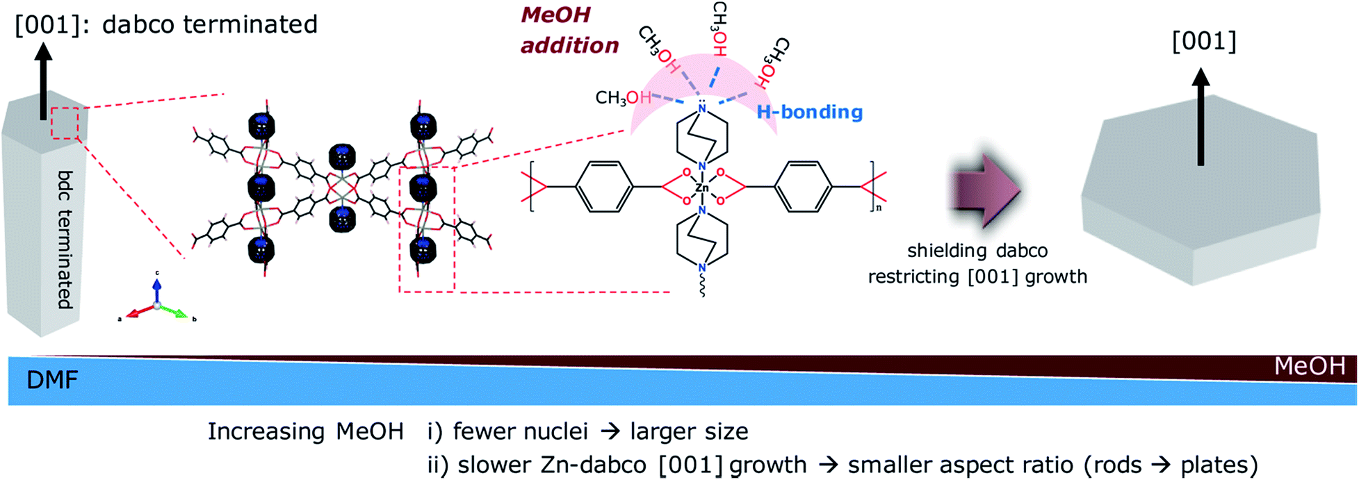 | ||
| Scheme 2 Suggested mechanism for morphology change from nanorods to microplates upon MeOH addition. | ||
The present solvent mediated approach enables the selective isolation of the pure crystalline ZBD phase with the desired structures by simply choosing the appropriate solvent composition. In addition, it is more energy efficient and environmentally friendly and requires less demanding synthesis equipment than conventional synthesis methods. In terms of framework stability and pore activation, the solvent template is highly preferred over the typical organic template (additive). The solvent generally has no direct interaction with the framework and is relatively easy to remove by volatile solvent exchange and thermal activation, thereby generating permanent porosity. In contrast, organic templates such as amines and polymers usually induce strong host–guest interactions and thus are often difficult to remove which might result in structural collapse.56–58
ZBD derived carbon and its application in EDLCs
The size and morphology of nano-MOFs and many other nanomaterials are inherently relevant to the type of targeted applications. As one example, EDLCs need a high packing density of electrode materials to achieve high volumetric capacitance desired in practical uses. As a proof of concept to demonstrate the morphology effect on volumetric capacitance, here we transformed two representative ZBDs with distinct morphologies and particle aspect ratios but comparable particle sizes (1D hexagonal nanorods of ZBDh-D10 and 2D tetragonal nanoplates of ZBDt-M10) (Table S1†) into MDCs via carbonization at 900 °C. The carbonized samples are denoted as ZBDh-D10-900 and ZBDt-M10-900, respectively.The morphologies of the parent ZBDs were well preserved after carbonization. Randomly yet homogeneously distributed mesopores were generated throughout the particles (Fig. 3a and b). ZBDh-D10-900 and ZBDt-M10-900 show type IV N2 sorption isotherms and an obvious hysteresis loop between P/P0 0.4 and 0.9, suggesting the presence of a substantial amount of mesopores (Fig. 3c). ZBDh-D10-900 has higher BET surface area and larger porosity than ZBDt-M10-900 (1490 vs. 1230 m2g−1), which is a similar trend to that in the parent ZBD precursors (Fig. 2d).
 | ||
| Fig. 3 Morphology conserved carbonization of ZBD. SEM and TEM images of (a) ZBDh-D10-900 and (b) ZBDt-M10-900, and their (c) N2 sorption isotherms and (d) pore size distributions. | ||
All Raman spectra have two broad peaks at 1342 and 1600 cm−1 that correspond to the D and G bands, respectively (Fig. S8†). The G-band arises from the stretching of any pair of sp2 sites whether in rings or chains. The D-band originates from the breathing mode of sp2 sites in rings of defects and disorders. Both carbons have an almost identical ID/IG intensity ratio near 0.97 and a broad G line width of 110 cm−1, suggesting the presence of graphitic cluster sizes in amorphous carbon smaller than 10 Å.59,60 The results reveal that both carbons have amorphous characteristics with a similar degree of graphitization and thus similar electrical conductivity. In addition, they have a comparable nitrogen content of 4.2 wt% which originated from dabco ligands, as determined by CHN elemental analysis (Table S3†). The N1S XPS spectra can be deconvoluted into pyridinic-N (398.2 eV), pyrrolic-N (399.5 eV), and graphitic-N (401.2 eV). The relative proportions of nitrogen species in both carbons are almost identical to each other (Fig. S9†). ICP-OES confirmed that most of the Zn (residual amount < 0.03 wt%) was removed during carbonization at 900 °C by carbothermal reduction and evaporation (Table S3†).
To demonstrate the morphology–volumetric capacitance relationships of ZBD derived carbons for EDLCs, ZBDh-D10-900 and ZBDt-M10-900 were fabricated into electrodes and characterized by cyclic voltammetry (CV) tests, in 1 M solution of tetraethylammonium tetrafluoroborate/acetonitrile (1 M TEABF4/AN), which is a common organic electrolyte.
Both ZBD-derived carbons present rectangle-like CV curves (0–2.5 V) without an obvious distortion even at a scan rate as high as 500 mV s−1, indicating a typical capacitive behavior with excellent rate capability (Fig. 4a and b). This is further underlined by the galvanostatic charging/discharging curve of ZBDt-M10-900 showing a symmetric triangular shape at 0.1 A g−1 and 10 A g−1 indicating the typical capacitor behavior (Fig. S10†). The small voltage drop even at 10 A g−1 reveals the low resistance of the EDLC. A voltage floating stability test performed for the EDLC cell with ZBDt-M10-900 as the electrode for 100 h at 2.5 V shows sufficient stability of the device (Fig. S11†). From a gravimetric perspective, due to the comparable surface area, conductivity and surface chemistry, the performances of the two carbons are rather similar to each other, exhibiting comparable specific capacitance and rate capability (around 80 F g−1 at 10 mV s−1, 50 F g−1 at 500 mV s−1) (Fig. 4c). However, the volumetric performance shows a significant difference. At the scan rate of 20 mV s−1 and 500 mV s−1, the differential current density of ZBDt-M10-900 is almost twice as high as that of ZBDh-D10-900 (Fig. 4a and b). This is further confirmed by the integral volumetric capacitance (Fig. 4d), where the volumetric capacitance of ZBDt-M10-900 is pronouncedly higher than that of ZBDh-D10-900 at all scan rates. This is attributed to the different pore structures and particle morphology. The meso- and macro-porosities of ZBDt-M10-900 are much lower compared with those of ZBDh-D10-900, leading to a higher density of the carbon materials in the electrodes. In addition, the 2D plate morphology of ZBDt-M10-900 can facilitate preferential and uniform alignment along the basal plane with relatively high packing density, as demonstrated by the high volumetric capacitances of various 2D materials.37,61,62 Simulation studies also show that particle elongation can lead to a decrease in packing density because of the increase in the orientationally excluded volume.63 Therefore, despite a similar gravimetric specific capacitance, ZBDt-M10-900 can provide higher volumetric capacitance. On the other hand, the lower meso–macroporosity of ZBDt-M10-900 results in the faster decay of capacitance at higher rates (Fig. 4c), as the meso/macropores tend to facilitate ion transport inside carbon electrodes. Note that ZBDt-M10-900 still provides higher volumetric capacitance over the entire range of scan rates investigated (Fig. 4d).
 | ||
| Fig. 4 EDLC performance comparison of ZBDh-D10-900 and ZBDt-M10-900 tested in 1 M TEABF4/AN using a two-electrode configuration: cyclic voltammograms (normalized to the electrode volume) of ZBDh-D10-900 and ZBDt-M10-900 at the scan rate of (a) 20 mV s−1 and (b) 500 mV s−1, and (c) gravimetric and (d) volumetric capacitance retention with the increase of scan rate. | ||
The general importance of the particle morphology and porosity on the volumetric efficiency of supercapacitor electrode materials is further shown by using non-commercial ordered mesoporous carbon CMK-3 as an additional reference material.64 CMK-3 typically shows a hexagonal rod-like shape and particles with sizes in the range of 1–3 μm.30 Its typical mesoporous structure is shown by the nitrogen physisorption isotherm (Fig. S12a†) with a pore volume of 1.23 cm g−1. The gravimetric capacitance is ∼80 F g−1, thus comparable to that of the two ZBD-derived carbons (Fig. S12c†). However, due to the mesoporous feature and different particle textures leading to moderate packing density, its volumetric capacitance is lower than that of ZBDt-M10-900 with the highest packing density, and higher than that of ZBDh-D10-900 with the lowest packing density (Fig. S12b†). Hence, the packing density generally plays a vital role in the volumetric capacitance. It has to be pointed out that in comparison to other recently reported supercapacitor electrode materials, ZBDt-M10-900 does not show a particularly impressive volumetric or gravimetric capacitance but the MOF-derived carbons are a suitable model system to evaluate the importance of the morphology of the electrode material particles for the volumetric capacitance of supercapacitors (Table S4†).
Conclusions
We reported a simple yet effective synthetic route toward nano-MOFs with controlled polymorphism, particle size and morphology under ambient conditions. The solvent effect on ZBD synthesis was systematically investigated for the first time by changing the kind and composition of the solvents. The solvent template effect enables the selective synthesis of 1D rod-like ZBDh in DMF and 2D plate-like ZBDt in MeOH. As DMF and MeOH work competitively, the use of DMF/MeOH with different ratios as a cosolvent further enables control over the crystal size and aspect ratios. Each solvent can act as a crystal modulator that decreases the rate of nucleation and thus increases the crystal size, e.g., the crystal size of ZBDh increases with increasing the amount of MeOH. The addition of MeOH induces the morphology transition from 1D rods to 2D plates. The polar protic MeOH reduces the reactivity of nucleophilic dabco and hinders the crystal growth along Zn-dabco [001], preferably inducing the formation of 2D plate-like ZBD. As a proof of concept to demonstrate the advantages of morphology controlled MOF, the resulting ZBDs are thermally transformed into hexagonal rod- and tetragonal plate-nanoporous carbons for application in EDLCs. Despite the similar gravimetric capacitance, 2D plate carbon shows two times higher volumetric capacitance than hexagonal rod carbon, highlighting the importance of MOF/MDC morphology for development of EDLC electrodes with a high packing density. The present solvent mediated MOF synthesis is facile yet highly effective in controlling the size and morphology of MOFs, and could be extended to the preparation of various nano-MOFs that are desired in a wide variety of potential applications.Conflicts of interest
There are no conflicts to declare.Acknowledgements
The authors acknowledge the Max Planck Society for funding. J. H. acknowledges the Max Planck Society for a postdoctoral scholarship. Open Access funding was provided by the Max Planck Society.Notes and references
- O. M. Yaghi, M. O'keeffe, N. W. Ockwig, H. K. Chae, M. Eddaoudi and J. Kim, Nature, 2003, 423, 705–714 CrossRef CAS PubMed.
- C. A. Trickett, A. Helal, B. A. Al-Maythalony, Z. H. Yamani, K. E. Cordova and O. M. Yaghi, Nat. Rev. Mater., 2017, 2, 17045 CrossRef CAS.
- Y.-B. Huang, J. Liang, X.-S. Wang and R. Cao, Chem. Soc. Rev., 2017, 46, 126–157 RSC.
- J. Zhou and B. Wang, Chem. Soc. Rev., 2017, 46, 6927–6945 RSC.
- H.-C. Lee, M. Fantin, M. Antonietti, K. Matyjaszewski and B. V. K. J. Schmidt, Chem. Mater., 2017, 29, 9445–9455 CrossRef CAS.
- J.-K. Sun and Q. Xu, Energy Environ. Sci., 2014, 7, 2071–2100 RSC.
- S. Dang, Q.-L. Zhu and Q. Xu, Nat. Rev. Mater., 2017, 3, 17075 CrossRef.
- W. Chaikittisilp, K. Ariga and Y. Yamauchi, J. Mater. Chem. A, 2013, 1, 14–19 RSC.
- Y. V. Kaneti, J. Tang, R. R. Salunkhe, X. Jiang, A. Yu, K. C. W. Wu and Y. Yamauchi, Adv. Mater., 2017, 29, 1604898 CrossRef PubMed.
- B. Y. Guan, X. Y. Yu, H. B. Wu and X. W. Lou, Adv. Mater., 2017, 29, 1703614 CrossRef PubMed.
- N. Stock and S. Biswas, Chem. Rev., 2012, 112, 933–969 CrossRef CAS PubMed.
- M. B. Majewski, H. Noh, T. Islamoglu and O. K. Farha, J. Mater. Chem. A, 2018, 6, 7338–7350 RSC.
- E. A. Flügel, A. Ranft, F. Haase and B. V. Lotsch, J. Mater. Chem., 2012, 22, 10119–10133 RSC.
- J. Klinowski, F. A. Paz, P. Silva and J. Rocha, Dalton Trans., 2011, 40, 321–330 RSC.
- T. Friscic, D. G. Reid, I. Halasz, R. S. Stein, R. E. Dinnebier and M. J. Duer, Angew. Chem., Int. Ed., 2010, 49, 712–715 CrossRef CAS PubMed.
- J. O. Kim, K. I. Min, H. Noh, D. H. Kim, S. Y. Park and D. P. Kim, Angew. Chem., Int. Ed., 2016, 55, 7116–7120 CrossRef CAS PubMed.
- E. Virmani, J. M. Rotter, A. Mähringer, T. von Zons, A. Godt, T. Bein, S. Wuttke and D. D. Medina, J. Am. Chem. Soc., 2018, 140, 4812–4819 CrossRef CAS PubMed.
- J. Huo, M. Marcello, A. Garai and D. Bradshaw, Adv. Mater., 2013, 25, 2717–2722 CrossRef CAS PubMed.
- T. Tsuruoka, S. Furukawa, Y. Takashima, K. Yoshida, S. Isoda and S. Kitagawa, Angew. Chem., Int. Ed., 2009, 48, 4739–4743 CrossRef CAS PubMed.
- J. Hwang, T. Heil, M. Antonietti and B. V. K. J. Schmidt, J. Am. Chem. Soc., 2018, 140, 2947–2956 CrossRef CAS PubMed.
- D. Tanaka and S. Kitagawa, Chem. Mater., 2007, 20, 922–931 CrossRef.
- B. X. Dong, X. J. Gu and Q. Xu, Dalton Trans., 2010, 39, 5683–5687 RSC.
- P. Long, H. Wu, Q. Zhao, Y. Wang, J. Dong and J. Li, MicroporousMesoporous Mater., 2011, 142, 489–493 CrossRef CAS.
- S.-Q. Zang, M.-M. Dong, Y.-J. Fan, H.-W. Hou and T. C. W. Mak, Cryst. Growth Des., 2012, 12, 1239–1246 CrossRef CAS.
- S. Bauer, C. Serre, T. Devic, P. Horcajada, J. Marrot, G. Ferey and N. Stock, Inorg. Chem., 2008, 47, 7568–7576 CrossRef CAS PubMed.
- T. Ahnfeldt, N. Guillou, D. Gunzelmann, I. Margiolaki, T. Loiseau, G. Ferey, J. Senker and N. Stock, Angew. Chem., Int. Ed., 2009, 48, 5163–5166 CrossRef CAS PubMed.
- Y. Wang, Y. Song and Y. Xia, Chem. Soc. Rev., 2016, 45, 5925–5950 RSC.
- W. Gu and G. Yushin, WIREs Energy. Environ., 2014, 3, 424–473 CrossRef CAS.
- R. Yan, M. Antonietti and M. Oschatz, Adv. Energy Mater., 2018, 8, 1800026 CrossRef.
- R. Yan, T. Heil, V. Presser, R. Walczak, M. Antonietti and M. Oschatz, Adv. Sustainable Syst., 2018, 2, 1700128 CrossRef.
- F. Béguin, V. Presser, A. Balducci and E. Frackowiak, Adv. Mater., 2014, 26, 2219–2251 CrossRef PubMed.
- L. Borchardt, M. Oschatz and S. Kaskel, Mater. Horiz., 2014, 1, 157–168 RSC.
- L. Zhang, F. Zhang, X. Yang, K. Leng, Y. Huang and Y. Chen, Small, 2013, 9, 1342–1347 CrossRef CAS PubMed.
- I. Tallo, T. Thomberg, H. Kurig, K. Kontturi, A. Jänes and E. Lust, Carbon, 2014, 67, 607–616 CrossRef CAS.
- H. Itoi, H. Nishihara, T. Kogure and T. Kyotani, J. Am. Chem. Soc., 2011, 133, 1165–1167 CrossRef CAS PubMed.
- Y. Zhou, M. Ghaffari, M. Lin, E. M. Parsons, Y. Liu, B. L. Wardle and Q. Zhang, Electrochim. Acta, 2013, 111, 608–613 CrossRef CAS.
- J. Yan, Q. Wang, T. Wei, L. Jiang, M. Zhang, X. Jing and Z. Fan, ACS Nano, 2014, 8, 4720–4729 CrossRef CAS PubMed.
- C. Liu, X. Yan, F. Hu, G. Gao, G. Wu and X. Yang, Adv. Mater., 2018, 30, 1705713 CrossRef PubMed.
- S. Dutta, A. Bhaumik and K. C. W. Wu, Energy Environ. Sci., 2014, 7, 3574–3592 RSC.
- A. Borenstein, O. Hanna, R. Attias, S. Luski, T. Brousse and D. Aurbach, J. Mater. Chem. A, 2017, 5, 12653–12672 RSC.
- Z. Lei, J. Zhang, L. L. Zhang, N. A. Kumar and X. S. Zhao, Energy Environ. Sci., 2016, 9, 1891–1930 RSC.
- Q. Wang, J. Yan and Z. Fan, Energy Environ. Sci., 2016, 9, 729–762 RSC.
- J. Hwang, C. Jo, M. G. Kim, J. Chun, E. Lim, S. Kim, S. Jeong, Y. Kim and J. Lee, ACS Nano, 2015, 9, 5299–5309 CrossRef CAS PubMed.
- D. N. Dybtsev, H. Chun and K. Kim, Angew. Chem., Int. Ed., 2004, 43, 5033–5036 CrossRef CAS PubMed.
- H. Chun, D. N. Dybtsev, H. Kim and K. Kim, Chem.–Eur. J., 2005, 11, 3521–3529 CrossRef CAS PubMed.
- P. Mishra, S. Mekala, F. Dreisbach, B. Mandal and S. Gumma, Sep. Purif. Technol., 2012, 94, 124–130 CrossRef CAS.
- J. Liu, J. Y. Lee, L. Pan, R. T. Obermyer, S. Simizu, B. Zande, J. Li, S. Sankar and J. K. Johnson, J. Phys. Chem. C, 2008, 112, 2911–2917 CrossRef CAS.
- Y. Chen, J. Lee, R. Babarao, J. Li and J. Jiang, J. Phys. Chem. C, 2010, 114, 6602–6609 CrossRef CAS.
- J. Hwang, H.-C. Lee, M. Antonietti and B. V. K. J. Schmidt, Polym. Chem., 2017, 8, 6204–6208 RSC.
- H.-C. Lee, J. Hwang, U. Schilde, M. Antonietti, K. Matyjaszewski and B. V. K. J. Schmidt, Chem. Mater., 2018, 30, 2983–2994 CrossRef CAS.
- S. Mochizuki, N. Ogiwara, M. Takayanagi, M. Nagaoka, S. Kitagawa and T. Uemura, Nat. Commun., 2018, 9, 329 CrossRef PubMed.
- H. Chun and J. Moon, Inorg. Chem., 2007, 46, 4371–4373 CrossRef CAS PubMed.
- M. Kondo, Y. Takashima, J. Seo, S. Kitagawa and S. Furukawa, CrystEngComm, 2010, 12, 2350–2353 RSC.
- K. Zhou, S. Chaemchuen, Z. Wu and F. Verpoort, MicroporousMesoporous Mater., 2017, 239, 28–33 CrossRef CAS.
- A. J. Parker, Chem. Rev., 1969, 69, 1–32 CrossRef CAS.
- D. T. de Lill and C. L. Cahill, Cryst. Growth Des., 2007, 7, 2390–2393 CrossRef CAS.
- Z. Zhang and M. J. Zaworotko, Chem. Soc. Rev., 2014, 43, 5444–5455 RSC.
- S. Cao, G. Gody, W. Zhao, S. Perrier, X. Peng, C. Ducati, D. Zhao and A. K. Cheetham, Chem. Sci., 2013, 4, 3573 RSC.
- J. Schwan, S. Ulrich, V. Batori, H. Ehrhardt and S. Silva, J. Appl. Phys., 1996, 80, 440–447 CrossRef CAS.
- A. Ferrari and J. Robertson, Phys. Rev. B: Condens. Matter Mater. Phys., 2000, 61, 14095–14107 CrossRef CAS.
- K. M. Zhao, S. Q. Liu, G. Y. Ye, Q. M. Gan, Z. Zhou and Z. He, J. Mater. Chem. A, 2018, 6, 2166–2175 RSC.
- M. R. Lukatskaya, O. Mashtalir, C. E. Ren, Y. Dall'Agnese, P. Rozier, P. L. Taberna, M. Naguib, P. Simon, M. W. Barsoum and Y. Gogotsi, Science, 2013, 341, 1502–1505 CrossRef CAS PubMed.
- A. V. Kyrylyuk and A. P. Philipse, Phys. Status Solidi A, 2011, 208, 2299–2302 CrossRef CAS.
- S. Jun, S. H. Joo, R. Ryoo, M. Kruk, M. Jaroniec, Z. Liu, T. Ohsuna and O. Terasaki, J. Am. Chem. Soc., 2000, 122, 10712–10713 CrossRef CAS.
Footnote |
| † Electronic supplementary information (ESI) available: Supplementary schematic representation, particle size distribution, aspect ratio, SEM images, N2 isotherms, TGA, and Raman spectra are included. See DOI: 10.1039/c8ta07700b |
| This journal is © The Royal Society of Chemistry 2018 |