 Open Access Article
Creative Commons Attribution 3.0 Unported Licence
Improved conversion efficiency of 10% for solid-state dye-sensitized solar cells utilizing P-type semiconducting CuI and multi-dye consisting of novel porphyrin dimer and organic dyes†
Naohiko
Kato
 *a,
Shinya
Moribe
a,
Masahito
Shiozawa
a,
Ryo
Suzuki
a,
Kazuo
Higuchi
a,
Akira
Suzuki
b,
Mareedu
Sreenivasu
b,
Katsuya
Tsuchimoto
b,
Koji
Tatematsu
c,
Katsuyoshi
Mizumoto
c,
Shoichi
Doi
c and
Tatsuo
Toyoda
c
aToyota Central Research and Development Laboratories, Inc., Nagakute-shi, Aichi 480-1192, Japan. E-mail: n-kato@mosk.tytlabs.co.jp
bAISIN Cosmos R&D Co.,Ltd., Kariya-shi, Aichi 448-8650, Japan
cAISIN SEIKI Co., Ltd., Kariya-shi, Aichi 448-8650, Japan
First published on 1st November 2018
Abstract
To realize highly efficient solid-state dye-sensitized solar cells (SDSCs), the absorption range of the dye should be extended to the near-IR range to increase short-circuit current density (Jsc); a high Jsc in turn requires a highly conductive p-type semiconductor. A newly developed dye (DIPDAB2) with a porphyrin dimer structure provided higher absorption coefficients than the conventional dye with a similar framework (DTBC) in the long wavelength range of 700–800 nm, leading to higher incident photon-to-current conversion efficiencies. The dip in the absorption spectrum of DIPDAB2 located at 500–700 nm between the Soret band and Q band was filled by combining with two kinds of organic dyes (D131 and D358). The multi-dye consisting of the three dyes realized a high Jsc over 20 mA cm−2. The use of copper iodide that has a higher conductivity than p-type organic semiconductors and copper complexes secured a high filling factor. Introduction of Li ions into the TiO2 photoelectrodes improved the open-circuit voltage (Voc) along with a slight increase in Jsc. Light soaking also contributed to a higher Voc. The conversion efficiency of the present SDSC was as high as 10%.
1. Introduction
Dye-sensitized solar cells (DSCs) have various advantages of color choice and transparency, as well as low costs and low energy consumption in production,1,2 compared with inorganic semiconductor-based solar cells. Using these unique characteristics, we have developed new application products such as light-emitting signboards, self-emitting guidance lights, etc., in which DSCs are installed as stand-alone power sources.3 Small-size DSCs provide a high conversion efficiency (η) of 14.7%.4 However, η and durability are in a trade-off relationship, as summarized in Fig. S1†.5–7 DSCs using a liquid electrolyte of a highly volatile solvent such as 3-methoxypropionitrile achieve a high η but suffer from low durability caused by solvent evaporation.5 The use of γ-butyrolactone extends the lifetime up to 3–5 years in an outdoor environment, while it appreciably decreases η.6 DSCs using ionic liquids are further durable; the lifetime estimated by an accelerated aging test is as long as 15 years.7 However, η is further lower owing to low diffusivity of the redox ions in viscous ionic liquids. The liquid electrolytes raise another issue of DSC modules that wide sealants separating neighbouring cells are required for high durability, resulting in narrowing of active areas.Replacement of the liquid electrolytes with solid-state p-type semiconductors can realize both high efficiency and high durability,8,9 by solving the evaporation issue with securing a high hole conductivity. Therefore, studies on solid-state DSCs (SDSCs) have been very active. Table 1 summarizes electric properties of candidate p-type materials and photovoltaic properties of SDSCs. Among them, copper iodide (CuI) is highly conductive and stable.10 The highest η of SDSCs using CuI is 7.4% coupled with the N3 dye.11 Although CsSnI3 perovskite is also highly conductive and achieves a higher η of 8.5% with the N719 dye,12 it is an unstable material; easily oxidized under ambient air condition. On the other hand, conductivities of p-type organic semiconductors such as 2,2′,7,7′-tetrakis-(N,N-di-p-methoxyphenyl-amine)-9,9′-spirobifluorene (spiro-OMeTAD) and the copper complexes are much lower than those of the inorganic materials.9,13–15
| p-type conductor/dye | Conductivity [mS cm−1] | VBMa [eV] | J sc [mA cm−2] | V oc [V] | Filling factor | Efficiency [%] | Stability of p-type materials |
|---|---|---|---|---|---|---|---|
| a Valence band maximum (VBM) was measured by photoelectron yield spectroscopy. b Ref. 22. c Ref. 11. d Ref. 12. e Ref. 13. f Ref. 9. g Ref. 14. h Ref. 15. | |||||||
| CuI/D149b | 308 | −5.00 | 12.8 | 0.65 | 0.72 | 6.0 | Stable |
| CuI/N3c | 308 | −5.00 | 14.5 | 0.73 | 0.70 | 7.4 | Stable |
| CuI/D131 + D358 + DIPDAB2 (this work) | 308 | −5.00 | 22.0 | 0.65 | 0.71 | 10.1 | Stable |
| CsSnI2.95F0.05 + 5% SnF2/N719d | 1111 | −4.90 | 15.9 | 0.72 | 0.74 | 8.5 | Unstable |
| Spiro-OMeTAD + Co complex FK102/Y123e | 0.02 | −5.20 | 9.5 | 0.98 | 0.77 | 7.2 | Unstable |
| Cu(dmp)2TFSI/LEG4f | 0.10 | −5.70 | 13.8 | 1.01 | 0.59 | 8.2 | Stable |
| Cu(tmby)2TFSI/Y123g | 0.17 | −5.67 | 13.9 | 1.08 | 0.73 | 11.0 | Stable |
| Cu(tmby)2TFSI/WS72h | 0.17 | −5.67 | 13.8 | 1.07 | 0.79 | 11.7 | Stable |
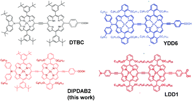
In the present study, we have focused on four items to improve η of SDSCs. The priority for this purpose is to widen the absorption range of the dye to increase the short-circuit current density (Jsc). Therefore, the first item is a new dye (DIPDAB2) with a porphyrin dimer structure to achieve higher absorption coefficients in the near-IR range. A conventional indoline dye (D149) has a narrow absorption band ranging up to 780 nm,16 resulting in a low Jsc of 13 mA cm−2. We have developed DIPDAB2 based on a donor–acceptor type porphyrin dimer dye: N-fused carbazole-zinc porphyrin-free-base porphyrin triad (DTBC) that sensitizes up to 900 nm.17 The molecular structure of DIPDAB2 is compared with that of DTBC in Fig. 1. There are refinements in DIPDAB2. A stronger electron donor unit of bis(4-hexylphenyl)amine moiety and a π conjugated system extended by a triple-bond-connected acceptor of benzoic acid red-shift the Q band. DTBC and other dyes of the porphyrin dimer structures previously developed: YDD6 (ref. 18) and LDD1 (ref. 19) are equipped with common substituents on the two porphyrin rings as shown in Fig. 1. The unique point of DIPDAB2 is that two different substituents are attached to the two porphyrin rings, which may inhibit aggregation of the dyes on the TiO2 electrodes. The second is the use of a multi-dye consisting of DIPDAB2 and two kinds of organic dyes: a yellow indoline dye (D131)20 and a red indoline rhodanine dye (D358),21 to cover a wide wavelength range from the visible to the near-IR. It has been demonstrated that co-sensitization can improve the performance of DSCs.18,19 We have selected co-sensitizers of D131 and D358 dyes to match DIPDAB2.
A LiI treatment after the dye-absorption on the TiO2 electrodes is employed to increase the open-circuit voltage (Voc), which is the third item. The last is light soaking that also increases Voc. The effects of the LiI treatment and light soaking on the present SDSCs are contrasting to those on liquid-type DSCs of improvements in Jsc with lowering in Voc.
Another important point is the selection of the p-type semiconductor. CuI and copper complexes are stable materials and hence the candidates, as stated above. Our strategy of the improvement in η is to increase Jsc, which requires high conductivity of the p-type material, because detrimental impacts of the inner resistance are more notable at a higher Jsc. Copper complexes show high efficiency,13–15 however, the conductivity is much lower than that of CuI. Therefore, we selected CuI for the p-type semiconductor. We have previously overcome the difficulties in filling the porous TiO2 electrodes with CuI by using TiO2 particles with a larger size than those for DSCs using liquid electrolytes, as shown in Fig. S2.†22
2. Experimental
2.1 Synthesis of DIPDAB2
We synthesized DIPDAB2 dye by the scheme illustrated in Fig. S3.† The products were confirmed to be the target structure of DIPDAB2, by elemental analysis, 1H-NMR, FT-IR, and MALDI-TOF-MS; see Fig. S4–S8.†2.2 Fabrication of DSCs with a liquid electrolyte
To compare the sensitization performance of DIPDAB2 with that of DTBC, DSCs using a liquid electrolyte were fabricated. Porous TiO2 electrodes consisting of nanoparticles of ca. 20 nm in diameter were screen-printed on glass substrates covered with transparent conductive oxide (TCO) layers, followed by a surface treatment using a TiCl4 aqueous solution. Then, the TiO2 electrodes of 10 mm × 7 mm in size were immersed in a 0.2 mM dye (DTBC or DIPDAB2) and 2 mM chenodeoxycholic acid (CDCA) acetonitrile/tert-butyl alcohol (1![[thin space (1/6-em)]](https://www.rsc.org/images/entities/char_2009.gif) :
:![[thin space (1/6-em)]](https://www.rsc.org/images/entities/char_2009.gif) 1) solution for 12 hours. The counter electrodes were prepared by chemical deposition of platinum onto the TCO glasses using a 0.05 M hexachloroplatinic acid solution at 400 °C. The dye-adsorbed TiO2 electrodes and platinum counter electrodes were faced to each other with polyolefin-based sealants. An liquid electrolyte containing I−/I3− redox couples using 0.6 M DMPII and 25 mM I2, 0.1 M LiI and 0.5 M 4-tert-butylpyridine in acetonitrile was injected into the cells.
1) solution for 12 hours. The counter electrodes were prepared by chemical deposition of platinum onto the TCO glasses using a 0.05 M hexachloroplatinic acid solution at 400 °C. The dye-adsorbed TiO2 electrodes and platinum counter electrodes were faced to each other with polyolefin-based sealants. An liquid electrolyte containing I−/I3− redox couples using 0.6 M DMPII and 25 mM I2, 0.1 M LiI and 0.5 M 4-tert-butylpyridine in acetonitrile was injected into the cells.
2.3 Fabrication of SDSCs with p-type semiconducting CuI
Double-layered TiO2 electrodes were prepared by screen printing on the TCO glasses. The first layers of around 5 μm in thickness were deposited using TiO2 particles with a size distribution ranging from 35 nm to 400 nm. The average pore size was 160 nm. Larger TiO2 particles of 400 nm in size were used for the 3 μm-thick second layers. The TiCl4 post treatments were repeated three times. The TiO2 electrodes of 10 mm × 7 mm in size were immersed in a 0.2 mM DIPDAB2 dye and 2 mM CDCA acetonitrile/tert-butyl alcohol (1![[thin space (1/6-em)]](https://www.rsc.org/images/entities/char_2009.gif) :
:![[thin space (1/6-em)]](https://www.rsc.org/images/entities/char_2009.gif) 1) solution for 1 hour, and then in 0.1 mM D131 and 0.3 mM D358 mixed ethanol solution for 16 hours. After the multi-dye adsorption, the TiO2 electrodes were immersed into 0.1–0.5 M LiI acetonitrile solutions. Solid-state CuI was injected into the dye-adsorbed porous TiO2 electrodes by dropping a CuI solution (CuI and 1-ethyl-3-methylimidazoliumthiocyanate in acetonitrile) followed by evaporation of the solvent as shown in S2.†22–24 Finally, the TiO2-dye-CuI electrodes were coupled with platinum foils as the counter electrodes to complete the SDSCs. SDSCs using D149 were also fabricated for comparison. LiI concentration distribution in the SDSCs was analysed by time-of-flight secondary ion mass spectrometry (TOF-SIMS).
1) solution for 1 hour, and then in 0.1 mM D131 and 0.3 mM D358 mixed ethanol solution for 16 hours. After the multi-dye adsorption, the TiO2 electrodes were immersed into 0.1–0.5 M LiI acetonitrile solutions. Solid-state CuI was injected into the dye-adsorbed porous TiO2 electrodes by dropping a CuI solution (CuI and 1-ethyl-3-methylimidazoliumthiocyanate in acetonitrile) followed by evaporation of the solvent as shown in S2.†22–24 Finally, the TiO2-dye-CuI electrodes were coupled with platinum foils as the counter electrodes to complete the SDSCs. SDSCs using D149 were also fabricated for comparison. LiI concentration distribution in the SDSCs was analysed by time-of-flight secondary ion mass spectrometry (TOF-SIMS).
2.4 Evaluation of the photovoltaic performance
The current–voltage (I–V) characteristics of the DSCs were determined by measuring the photocurrent using an I–V tester (IV-9701, WACOM) under the simulated solar insolation of AM1.5G produced using a 1 kW xenon lamp and a 400 W halogen lamp (WXS-155S-L2, WACOM). The incident photon-to-current conversion efficiency (IPCE) was measured in a wavelength range of 300–900 nm using an equipment (CEP-2000, BUNKOU-KEIKI) specially designed for DSCs consisting of a xenon lamp, a monochromator, a digital lock-in amplifier, and a Keithley 2400 source meter.3 Results and discussion
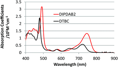
As mentioned above, at first we have designed and synthesized DIPDAB2 with a porphyrin dimer structure to achieve higher absorption coefficients in the near-IR range than those of conventional DTBC.17 UV-vis absorption spectra of DIPDAB2 and DTBC adsorbed on porous TiO2 films shown in Fig. 2 confirm the red-shifted Q band with higher absorbance of DIPDAB2. Comparison with the other porphyrin dimer dyes: YDD6 (ref. 18) and LDD1 (ref. 19) are summarized in Table S1.† The absorption coefficient of DIPDAB2 at the Q band was much higher than that of YDD6 and comparable with that of LDD1. Photovoltaic performance of the liquid DSCs are shown in Fig. 3 and Table S1.† The IPCE and conversion efficiency for DIPDAB2 were much higher than those for DTBC, reflecting the notable enhancement in the absorbance. Similar trends were observed for YDD6 (ref. 18) and LDD1 (ref. 19) according to the absorption coefficients.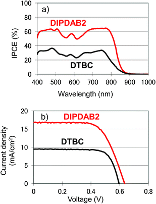 | ||
| Fig. 3 (a) IPCE spectra, (b) current–voltage (I–V) curves under 1 sun irradiation of the liquid electrolyte DSCs using DIPDAB2 and DTBC. | ||
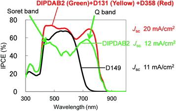
The second item is the use of a multi-dye. Although DIPDAB2 exhibits high absorbance in the near-IR range as described above, there is a dip between the Soret band centered at 500 nm and the Q band located at around 700 nm. To fill the gap and secure highly efficient sensitization in the whole of the visible-near-IR range, a multi-dye consisting of DIPDAB2 and two kinds of organic dyes: D131 and D358 was used. The molecular structures of D131 and D358 are displayed in Fig. S9.†Fig. 4 compares the IPCE spectrum of the SDSC using the multi-dye (DIPDAB2 + D131 + D358) with those for D149 and DIPDAB2. D131 and D358 well complemented the dip between the Soret band and Q band originating from the porphyrin dimer in DIPDAB2. As a result, the IPCE spectrum for the multi-dye covered a notably wider range than that for D149, leading to a dramatic improvement in Jsc to over 20 mA cm−2 estimated from the IPCE spectrum. We consider that the multi-dye inhibits the aggregation of the single DIPDAB2 dye.18,19 As the result, the IPCE for the multi-dye in the absorption range of the Q band was much higher than the single DIPDAB2 dye.
The third item is the post treatment using LiI. The dye-adsorbed TiO2 electrodes were immersed in LiI acetonitrile solutions. Fig. 5 shows the I–V curves of the SDSCs with and without the post treatment. Time-of-flight secondary ion mass spectroscopy (TOF-SIMS) mappings of Li displayed in Fig. S10† revealed uniform distribution and higher concentrations of Li in the TiO2 electrodes for higher concentrations of the LiI solutions. With increasing Li concentration, Voc increased from 0.59 V for no LiI treatment, and eventually reached 0.65 V using the 0.5 M LiI solution with a slight increase in Jsc.
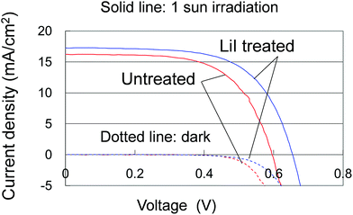 | ||
| Fig. 5 Current–voltage (I–V) curves of the SDSCs under 1 sun irradiation and in the dark with and without the 0.5 M LiI post treatment. | ||
It is well known that introduction of LiI into an electrolyte consisting of I−/I3− redox couples used for DSCs increases Jsc while it decreases Voc.25 Li ions adsorbed on the TiO2 electrodes lowers the conduction-band minimum (CBM) of the TiO2, leading to a higher efficiency of electron injection from the photo-excited dyes to the TiO2 and consequently a higher Jsc. On the other hand, Voc lowers as it is determined from the energy difference between the CBM of the TiO2 and the redox level. The contrasting result of increasing Voc for the present SDSCs suggests a different mechanism of the LiI treatment effect, like reduction of carrier recombination at the interfaces between the TiO2 and CuI.
The fourth item is light soaking. During the light soaking at 1 sun, Voc gradually increased with only a slight decrease in Jsc, as shown in Fig. 6a. After a half hour, Voc reached 0.65 V (an improvement by 0.07 V) with securing a high Jsc of 22 mA cm−2 for the best-performance cell. The I–V curves of the SDSCs using the multi-dye and D149 are compared in Fig. 6b. Reflecting the wider sensitivity range, Jsc for the multi-dye was much higher than that for D149. In addition, there was no degradation of the filling factor (FF) in spite of the higher Jsc, owing to the high conductivity of CuI. As a result, η for the multi-dye was significantly improved to be 10.1% compared with that for D149, and substantially exceeded the previously reported highest value of 7.4% using CuI and the N3 dye.11 The reproducibility was fairly good as summarized in Table S2.† It is worthy to note that the effect of the light soaking on the SDSCs were also contrasting to that of higher Jsc and lower Voc on the DSCs using liquid electrolytes, although the present mechanism is not clear.
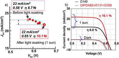 | ||
| Fig. 6 (a) Relation between Jsc and Voc of the SDSCs before/after the light soaking, (b) current–voltage (I–V) curves of the SDSCs under 1 sun irradiation using the multi-dye and D149. | ||
The photovoltaic performance of the SDSCs employing the four items is compared with previously reported ones in Table 1. The present Jsc of 22 mA cm−2 is extremely higher than those of the other SDSCs, with no remarkable degradation of FF compared with the other SDSCs using CuI. The disadvantage for CuI is lower Voc than those for the other p-type semiconductors, caused by carrier recombination at the CuI surfaces.26 It has been reported that CuI surfaces act as hole trapping sites.26 The maximal Voc determined from the difference between the CBM of TiO2 (−4.2 eV from the vacuum level) and the VBM of CuI (−5.2 eV) is 1.0 V.8 If Voc could be improved to close to the ideal value with securing a high Jsc of 22 mA cm−2, η of 15% would be attained. Thus, the SDSCs using the multi-dye consisting of the new porphyrin dimer dye DIPDAB2 and organic dyes with CuI are promising for highly efficient and cost-effective solar cells.
4 Conclusions
We have established a strategy to improve the conversion efficiency of SDSCs; to widen the absorption range leading to a high current density and to use highly conductive p-type CuI for solid-state electrolytes. The multi-dye consisting of the newly developed DIPDAB2 with a porphyrin dimer structure and two kinds of organic dyes (D131 and D358) covered notably wider range with high IPCE compared with conventional porphyrin dimer dye DTBC and organic dyes, leading to an extremely high current density over 22 mA cm−2. The CuI electrolyte fully injected into the porous TiO2 electrodes secured a high FF. The LiI treatments to the dye-absorbed TiO2 electrodes and light soaking of the completed SDSCs improved Voc with a slight increase in Jsc. Eventually, the conversion efficiency reached as high as 10%.Conflicts of interest
There are no conflicts to declare.Acknowledgements
We are grateful to Dr Yasuhiko Takeda and Prof. Tomoyoshi Motohiro for helpful discussion and suggestions. Dr Paidi Yella Reddy is acknowledged for the design of the novel porphyrin dimer dye.Notes and references
- B. O'Regan and M. Grätzel, Nature, 1991, 353, 737 CrossRef.
- M. Grätzel, Acc. Chem. Res., 2009, 42, 1788 CrossRef PubMed.
- T. Miyasaka, Trends and Topics in Sensitized and Organic Solar Cells, CMC, Japan, 2012, ch. 3 Search PubMed.
- K. Kakiage, Y. Aoyama, T. Yano, K. Oya, J. Fujisawa and M. Hanaya, Chem. Commun., 2015, 51, 15894 RSC.
- T. Toyoda, T. Sano, J. Nakajima, S. Doi, S. Fukumoto, A. Ito, T. Tohyama, M. Yoshida, T. Kanagawa, T. Motohiro, T. Shiga, K. Higuchi, H. Tanaka, Y. Takeda, T. Fukano, N. Katoh, A. Takeichi, K. Takechi and M. Shiozawa, J. Photochem. Photobiol., A, 2004, 164, 203 CrossRef CAS.
- N. Kato, Y. Takeda, K. Higuchi, A. Takeichi, E. Sudo, H. Tanaka, T. Motohiro, T. Sano and T. Toyoda, Sol. Energy Mater. Sol. Cells, 2009, 93, 893 CrossRef CAS.
- N. Kato, K. Higuchi, H. Tanaka, J. Nakajima, T. Sano and T. Toyoda, Sol. Energy Mater. Sol. Cells, 2011, 95, 301 CrossRef CAS.
- K. Tennakone, J. Phys. D: Appl. Phys., 1998, 31, 1492 CrossRef CAS.
- M. Freitag, Q. Daniel, M. Pazoki, K. Sveinbjörnsson, J. Zhang, L. Sun, A. Hagfeldt and G. Boschloo, Energy Environ. Sci., 2015, 8, 2634 RSC.
- D. Chen, Y. Wang, Z. Lin, J. Huang, X. Chen, D. Pan and F. Huang, Cryst. Growth Des., 2010, 10, 2057 CrossRef CAS.
- H. Sakamoto, S. Igarashi, M. Uchida, K. Niume and M. Nagai, Org. Electron., 2012, 13, 514 CrossRef CAS.
- I. Chung, B. Lee, J. He, R. P. H. Chang and M. G. Kanatzidis, Nature, 2012, 485, 486 CrossRef CAS PubMed.
- J. Burschka, A. Dualeh, F. Kessler, E. Baranoff, N.-L. Cevey-Ha, C. Yi, M. K. Nazeeruddin and M. Grätzel, J. Am. Chem. Soc., 2011, 133, 18042 CrossRef CAS PubMed.
- Y. Cao, Y. Saygili, A. Ummadisingu, J. Teuscher, J. Luo, N. Pellet, F. Giordano, S. M. Zakeeruddin, J.-E. Moser, M. Freitag, A. Hagfeldt and M. Grätzel, Nat. Commun., 2017, 8, 15390 CrossRef PubMed.
- W. Zhang, Y. Wu, H. W. Bahng, Y. Cao, C. Yi, Y. Saygili, J. Luo, Y. Liu, L. Kavan, J. E. Moser, A. Hagfeldt, H. Tian, S. M. Zakeeruddin, W. H. Zhu and M. Grätzel, Energy Environ. Sci., 2018, 11, 1779 RSC.
- T. Horiuchi, H. Miura, K. Sumioka and S. Uchida, J. Am. Chem. Soc., 2004, 126, 12218 CrossRef CAS PubMed.
- Y. Liu, H. Lin, J. Ting Dy, K. Tamaki, J. Nakazaki, D. Nakayama, S. Uchida, T. Kubo and H. Segawa, Chem. Commun., 2011, 47, 4010 RSC.
- H.-P. Wu, Z.-W. Ou, T.-Y. Pan, C.-M. Lan, W.-K. Huang, H.-W. Lee, N. M. Reddy, C.-T. Chen, W.-S. Chao, C.-Y. Yeh and E. W.-G. Diau, Energy Environ. Sci., 2012, 5, 9843 RSC.
- J.-W. Shiu, Y.-C. Chang, C.-Y. Chan, H.-P. Wu, H.-Y. Hsu, C.-L. Wang, C.-Y. Lin and E. W.-G. Diau, J. Mater. Chem. A, 2015, 3, 1417 RSC.
- H. Tanaka, A. Takeichi, K. Higuchi, T. Motohiro, M. Takata, N. Hirota, J. Nakajima and T. Toyoda, Sol. Energy Mater. Sol. Cells, 2009, 93, 1143 CrossRef CAS.
- M. Takata, Introduction of photosensitive dyes for solar cells, https://www.mpm.co.jp/electronic/solar-cells/index.html, 2018 Search PubMed.
- S. Moribe, A. Takeichi, J. Seki, N. Kato, K. Higuchi, K. Ueyama, K. Mizumoto and T. Toyoda, Appl. Phys. Express, 2012, 5, 112302 CrossRef.
- G. R. A. Kumara, A. Konno, K. Shiratsuchi, J. Tsukahara and K. Tennakone, Chem. Mater., 2002, 14, 954 CrossRef CAS.
- S. Moribe, N. Kato, K. Higuchi, K. Mizumoto and T. Toyoda, Appl. Phys. Express, 2017, 10, 042301 CrossRef.
- S. Pelet, J.-E. Moser and M. Grätzel, J. Phys. Chem. B, 2000, 104, 1791 CrossRef CAS.
- V. P. S. Perera and K. Tennakone, Sol. Energy Mater. Sol. Cells, 2003, 79, 249 CrossRef CAS.
Footnote |
| † Electronic supplementary information (ESI) available. See DOI: 10.1039/c8ta06418k |
| This journal is © The Royal Society of Chemistry 2018 |

