Confined heat treatment of a Prussian blue analogue for enhanced electrocatalytic oxygen evolution†
Yanhua
Zeng‡
,
Gao-Feng
Chen‡
,
Zhouyang
Jiang
,
Liang-Xin
Ding
*,
Suqing
Wang
and
Haihui
Wang
 *
*
School of Chemistry & Chemical Engineering, South China University of Technology, Guangzhou 510640, China. E-mail: lxding@scut.edu.cn; hhwang@scut.edu.cn
First published on 3rd August 2018
Abstract
Frame-like coordination polymers (FCPs) are very promising catalyst materials because of their highly ordered structures and diversified pore surfaces. However, their poor conductivity and stability hinder their application in the field of electrocatalysis. Herein, for the first time, we try to use an FCP such as a Prussian blue analogue (PBA) directly as a catalyst candidate for the oxygen evolution reaction (OER), and report an ingenious confined heat treatment strategy to maximize its electrocatalytic performance. Our synthesized and treated NiFeII-PBA crystals were self-grown on conducting substrates and consisted of small nanocrystals, which enabled them to facilitate electron transport and expose more active sites. As a result, the NiFeII-PBA crystals exhibited an excellent electrocatalytic performance towards oxygen evolution in alkaline media, and an overpotential of only 285 mV is needed to achieve a current density of 50 mA cm−2.
As there has been a significant increase in fossil energy consumption, and environmental pollution has worsened, humankind has searched for clean and renewable energy extensively. Hydrogen has been considered as a fascinating alternative to unsustainable fossil fuels.1–3 Electrocatalytic water splitting is a feasible method for the large-scale production of hydrogen,1 since this method is operated easily, causes no environmental pollution and produces high purity hydrogen.4 However, for anodic water oxidation, the oxygen evolution reaction (OER) hampers the extensive development of water electrocatalysis due to its sluggish kinetics.5,6 Therefore developing efficient catalysts to decrease the overpotential for the OER is crucial for accelerating the water splitting process.1 Currently, IrO2 and RuO2 are recognized as the most efficient and stable catalysts for the OER.7,8 However, their scarcity and high price hinder their extensive commercial applications.9,10
In recent years, although good progress has been made with developing alternative catalysts with earth abundant materials, their catalytic performance is still unsatisfactory (the overpotential of the OER is still relatively high).11 Therefore, it is necessary to develop more efficient electrocatalysts for oxygen evolution.
Recently, frame-like coordination polymers, such as metal–organic frameworks (MOFs), have drawn great attention in the catalysis field due to their innate highly ordered structures, large contactable surface area, and easily tunable central metals.12–14 Additionally, their adjustable ligands and identical structures inside and outside give them an outstanding advantage for functionalizing active sites and studying catalytic mechanisms. Nevertheless, due to their poor stability in proton solution and low electrical conductivity (current research mainly uses them as precursors to prepare metal-doped carbon-based catalyst materials)15,16 there are very few reports on their direct use as catalysts for electrochemical applications. To explore their electrochemical properties, recent attempts have been made to obtain alkali-stable MOFs (metal hydroxide mimicking MOFs) via a ligand metathesis strategy,17 which were successfully used to catalyze the OER, but this strategy was only suitable for special MOFs.18,19 Therefore, it is still a challenge to make full use of their structural advantages to realize electrocatalytic applications.
To address this issue, some studies have shown that the use of inorganic ligands instead of organic ligands can realize the convenient synthesis of coordination polymers in aqueous solution, and thus can expand their electrochemical applications. A typical example is Prussian blue analogues (PBAs, AxM[M′(CN)6]y·□1−y·nH2O: A = alkali metal; M,M′ = transition metals; □ = M′(CN)6 vacancy; denoted MM′-PBA), which not only have good stability in aqueous solution, but also possess both redox active sites and mixed conductivity.20–23 Besides, compared with organic ligands, the use of inorganic ligands can also effectively increase the number and density of active metals in the frame-like structure.
Inspired by these, herein we first tried to use a Prussian blue analogue (PBA) directly as a catalyst candidate for the OER, and also described a simple and feasible in situ synthesis and surface optimization strategy to enable the PBA with an excellent electrocatalytic performance by boosting its electron transport and the exposure of active sites. More specifically, [K2NiFe(CN)6] (denoted NiFeII-PBA) was synthesized in situ on a nickel foam (NF) substrate for the first time by the self-sacrifice of the NF substrate as the nickel source. Structure tailoring of the NiFeII-PBA crystals was further achieved using confined heat treatment with salt-encapsulation (see the ESI† for the detailed preparation and post-processing processes). Compared to conventional PBA strategies, the strategy we propose here has the following additional advantages: (i) using NF as the substrate and nickel source can not only provide a conductive network, but also ensures that the growing NiFeII-PBA has close contact with the conductive substrate; (ii) by using the confined heat treatment method, the NiFeII-PBA crystals can not only form hollow structures, but can also be comminuted at a relatively low temperature due to their volume expansion/contraction and local pyrolysis. Obviously, the resulting hollow structures will be beneficial for the rapid transmission and diffusion of active species. Besides, powdery NiFeII-PBA can expose more active sites, and a small amount of carbon formed by local pyrolysis can be used as a conductive linker to facilitate electron transport. These advantages ensure that NiFeII-PBA has better physical or chemical properties. As expected, as-prepared NiFeII-PBA showed comparable OER activity to standard RuO2.
The initial NiFeII-PBA crystals grown on NF (denoted NiFeII-PBA/NF) are confirmed by X-ray diffraction (XRD) (Fig. S1, ESI†). The typical peaks are consistent with the standard XRD pattern (PDF# 20-0915) and conventional synthetic NiFeII-PBA, indicating that NiFeII-PBA was successfully synthesized by the self-sacrifice of the NF substrate as the nickel source. To tailor the surface structure of the NiFeII-PBA crystals, a confined heat treatment at different temperatures was performed. The corresponding XRD results shown in Fig. 1a show that the diffraction peaks of NiFeII-PBA located at 40° and 44° begin to split when the temperature is above 400 °C, and a series of new diffraction peaks begin to appear around 30°, which means that the NiFeII-PBA crystals are beginning to become pyrolyzed. It should be pointed out that even if the temperature rises to 500 °C, the typical diffraction peaks of NiFeII-PBA remain relatively complete, which indicates that the NiFeII-PBA crystals still maintain their crystal structure, and only a few of them are pyrolyzed. This result is also confirmed by Raman spectroscopy (Fig. 1b). From Fig. 1b, it can be clearly seen that, when the temperature is higher than 400 °C, the characteristic peaks of carbon begin to appear around 1340 cm−1 and 1590 cm−1,24 suggesting a gradual carbonation. In addition, the intensity of the peaks located at 2095 cm−1 and 2137 cm−1, which correspond to the symmetric vibrational stretch of cyanide,25 is also gradually weakening, but they can still be observed below 500 °C. It is clear that this trend of change is almost entirely consistent with the XRD results.
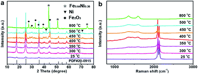 | ||
| Fig. 1 (a) XRD patterns and (b) Raman spectra of the NiFeII-PBA crystals after heat treatment at different temperatures (25 °C represents initial NiFeII-PBA without heat treatment). | ||
Scanning electron microscopy (SEM) images show that the NiFeII-PBA nanocubes are grown uniformly on a nickel foam substrate (Fig. S2†) with a chain distribution and an average side length of ≈100 nm (Fig. 2a and S3†), which is distinguished from the NiFeII-PBA powder with a disordered distribution (Fig. S4†). After the confined heat treatment with salt encapsulation at 400 °C (denoted NiFeII-PBA-SE/NF-400), only the contour of the cube can be seen (Fig. 2b), indicating that the surface morphology of NiFeII-PBA has changed obviously. In contrast, without salt encapsulation (denoted NiFeII-PBA-NSE/NF-400), almost no cubic structure can be observed, and the NiFeII-PBA nanocubes are transformed into irregular particles and are glued together (Fig. S5†). Transmission electron microscopy (TEM) showed that NiFeII-PBA-SE/NF-400 formed hollow structures and a large number of small particles (∼5 nm) appeared on their surface (Fig. 2c and d). Compared to the initial and unencapsulated NiFeII-PBA (Fig. S6a and b†), it can be determined that the formation of the hollow structures is mainly due to salt encapsulation. EDS analysis (Fig. S7†) and EDS mapping images (Fig. 2e) indicate that the NiFeII-PBA-SE/NF-400 sample mainly contains Ni, Fe, N and O, and their distribution in the NiFeII-PBA-SE/NF-400 sample is uniform. O, Ni and Fe are very consistent in the elemental profile, suggesting the formation of metal oxides, which could be due to the oxidation of highly active Ni and Fe from partial pyrolysis. More detailed structural analysis reveals that the crystalline particles are NiFeII-PBA with a (422) planar spacing of 0.205 nm and the amorphous particles should be amorphous carbon and metallic oxides derived from local pyrolysis (Fig. 2f). In addition, to intuitively compare the effect of heat treatment temperature on the structure, a completely carbonized sample was obtained by the heat treatment of NiFeII-PBA at 800 °C, which was denoted NiFeII-PBA-SE/NF-800. Obviously different from NiFeII-PBA-SE/NF-400, the TEM images in Fig. S8† show that the cubic structure of NiFeII-PBA completely collapsed and was pulverized into a typical metal-embedded carbon material. These structural differences further confirm that NiFeII-PBA can still maintain its basic structure after heat treatment at 400 °C.
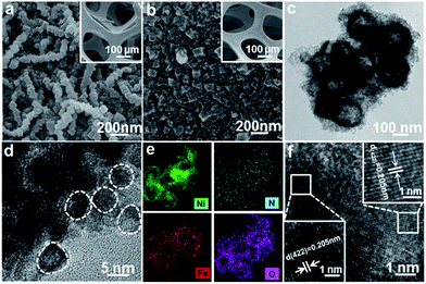 | ||
| Fig. 2 SEM images of (a) initial NiFeII-PBA/NF without heat treatment, (b) NiFeII-PBA-SE/NF-400, (c, d, f) HRTEM images and (e) the elemental distribution mapping of NiFeII-PBA-SE/NF-400. | ||
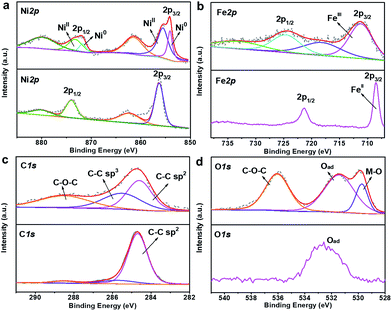
X-ray photoelectron spectroscopy (XPS) was employed to investigate the valence state and composition evolution during the confined heat treatment process. The obvious difference of the XPS survey spectra in Fig. S9† indicates that the surface composition of NiFeII-PBA has changed obviously before and after heat treatment. The loss of the N peak and the apparent weakening of the C peak after 400 °C heat treatment mean that the cyanide on the NiFeII-PBA surface is almost completely pyrolyzed. The high resolution XPS spectra of Ni 2p shown in Fig. 3a show that two new peaks appear at 854.2 eV and 871.7 eV after heat treatment, corresponding well to the binding energy of metallic nickel,4,26–28 which should be generated by the reduction of oxidized nickel by carbon during pyrolysis. Meanwhile, the main Fe 2p peaks have an obvious positive shift after heat treatment (Fig. 3b), which can be attributed to the oxidation of low valence iron caused by the pyrolysis of ligands on the surface.27,29,30 In the high-resolution XPS spectra of C 1s (Fig. 3c), besides the main C![[double bond, length as m-dash]](https://www.rsc.org/images/entities/char_e001.gif) C peak at 284.7 eV, there are two obvious additional peaks with a higher binding energy at 285.8 eV and 288.6 eV for NiFeII-PBA-SE/NF-400, which correspond to the C–C and C–O–C peaks caused by pyrolysis, respectively.31 In addition, two additional O 1s peaks with binding energies of 529.8 eV and 536 eV can also be observed for NiFeII-PBA-SE/NF-400 (Fig. 3d), which can be ascribed to the M–O peak formed by metal oxidation (combined with the XPS Fe 2p spectra, the Fe–O peak is most likely here) and the C–O–C peak.11,32 These high resolution XPS spectra data further confirm that there is a change on the surface of NiFeII-PBA after confined heat treatment.
C peak at 284.7 eV, there are two obvious additional peaks with a higher binding energy at 285.8 eV and 288.6 eV for NiFeII-PBA-SE/NF-400, which correspond to the C–C and C–O–C peaks caused by pyrolysis, respectively.31 In addition, two additional O 1s peaks with binding energies of 529.8 eV and 536 eV can also be observed for NiFeII-PBA-SE/NF-400 (Fig. 3d), which can be ascribed to the M–O peak formed by metal oxidation (combined with the XPS Fe 2p spectra, the Fe–O peak is most likely here) and the C–O–C peak.11,32 These high resolution XPS spectra data further confirm that there is a change on the surface of NiFeII-PBA after confined heat treatment.
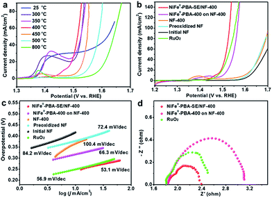
The electrocatalytic OER performances of the NiFeII-PBA-SE/NF catalysts at different heat treatment temperatures were investigated in 1 M KOH using a standard three-electrode system. For comparison, initial NF, preoxidized NF, NF-400, NiFeII-PBA powder at different heat treatment temperatures and commercial RuO2 (powder loading: 2.0 mg cm−2) were also investigated. Fig. 4a shows the iR-corrected linear sweep voltammetry (LSV) curves of the NiFeII-PBA-SE/NF catalysts at heat treatment temperatures from 300 °C to 800 °C. It is very clear that the heat treatment temperature has a great influence on the catalytic performance. Specifically, NiFeII-PBA-SE/NF-400 shows the highest OER activity with the lowest overpotential of 285 mV to achieve a current density of 50 mA cm−2. The order of catalytic activity at different heat treatment temperatures is NiFeII-PBA-SE/NF-400 > NiFeII-PBA-SE/NF-300 ≈ NiFeII-PBA-SE/NF-350 > NiFeII-PBA-SE/NF-450 > NiFeII-PBA-SE/NF-500 > NiFeII-PBA-SE/NF-800. This result is also consistent with the order of catalytic activity of the treated powder samples (Fig. S10†). Combined with the results of the structural and composition characterization, the optimum catalytic performance of NiFeII-PBA-SE/NF-400 is mainly due to its suitable heat treatment temperature. In other words, as the initial pyrolysis temperature of NiFeII-PBA, the optimal reactive active sites can be formed at 400 °C. In addition, there is an obvious oxidation peak between 1.35 V and 1.45 V when the heat treatment temperature is below 400 °C, which is ascribed to the occurrence of the oxidation of the low valence central metal on the NiFeII-PBA surface. When the heat treatment temperature is higher than 400 °C, the pre-oxidation peak between 1.35 V and 1.45 V disappears, which should be due to the formation of a carbonation layer through surface pyrolysis to inhibit further oxidation of NiFeII-PBA. This phenomenon also indicates that the surface stability of the catalyst is enhanced with an increase in heat treatment temperature. Besides, we also observe that, with an increase in heat treatment temperature, the catalytic performance of the sample shows a significant decline, which means that the catalytic properties of the heat-treated samples are mainly due to residual NiFeII-PBA, rather than the carbon and metal or metal oxides formed by pyrolysis. Additionally, considering the low catalytic activity of NiFeII-PBA-SE/NF-25 and NiFeII-PBA-SE/NF-800, the small amount of carbon and metal or metal oxides formed should only play a role in enhancing the conductivity and stability of NiFeII-PBA-SE/NF-400.
Further iR-corrected LSV curves of the contrast samples are shown in Fig. 4b. It can be clearly seen that the NiFeII-PBA-SE/NF-400 catalyst shows higher OER catalytic activity than commercial RuO2, NiFeII-PBA-400 powder, initial NF, preoxidized NF and NF-400, further confirming the superior catalytic activity of the NiFeII-PBA-SE/NF-400 catalyst for the OER. It is also higher than that of other recently reported OER catalysts which are derived from MOFs or PBAs (detailed comparisons are shown in Tables S1 and S2†). To evaluate the catalytic kinetics of the above catalysts for the OER, the corresponding Tafel slopes (η vs. log(j)) are constructed and are shown in Fig. 4c. Obviously, the Tafel slope of NiFeII-PBA-SE/NF-400 is about 53.1 mV dec−1, which is much smaller than that of NiFeII-PBA-400 powder (66.3 mV dec−1), and even smaller than that of commercial RuO2 (56.9 mV dec−1), indicating the more favorable OER electrocatalytic kinetics of the NiFeII-PBA-SE/NF-400 catalyst.
It should be pointed out that, aside from the best reactive sites being created by heat treatment, the outstanding oxygen evolution performance of NiFeII-PBA-SE/NF-400 may also be related to the nature of the in situ growth on the NF and the salt encapsulation treatment. It can be expected that the in situ growth strategy can maximize the contact between NiFeII-PBA and the foamed nickel substrate and thus enhance the electron transport and stability of the catalyst electrode. To verify the actual effect, electrochemical impedance spectroscopy (EIS) was employed to assess the charge transfer resistance of NiFeII-PBA-SE/NF-400 compared with that of the NiFeII-PBA-400 powder and RuO2 coated on NF. Also, the EIS of NF-400, preoxidized NF and initial NF were examined in advance to exclude the support contribution (Fig. S11†). The Nyquist plots shown in Fig. 4d show that NiFeII-PBA-SE/NF-400 (1.6 V, Rct = 0.55 Ω) has a smaller charge transfer resistance compared with commercial RuO2 (1.6 V, Rct = 0.75 Ω), which is much smaller than that of the simply coated sample (1.6 V, Rct = 1.29 Ω), suggesting a more convenient electronic transmission on the NiFeII-PBA-SE/NF-400 catalyst electrode.
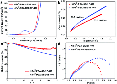
Furthermore, to confirm the effect of salt encapsulation on the catalytic performance of NiFeII-PBA, the OER catalytic performance of NiFeII-PBA-NSE/NF-400 (without salt encapsulation) was also investigated. Fig. 5a clearly shows that NiFeII-PBA-NSE/NF-400 requires a higher overpotential (295 mV) to achieve a current density of 50 mA cm−2 compared with NiFeII-PBA-SE/NF-400 (285 mV). The Tafel slope of NiFeII-PBA-NSE/NF-400 is also larger than that of NiFeII-PBA-SE/NF-400 (Fig. 5b). Combined with the BET characterization results (Fig. S12†), the enhanced OER catalytic activity of NiFeII-PBA-SE/NF-400 is mainly attributed to its larger active area. More directly, we compare their OER catalytic activity based on the BET surface area. As shown in Fig. S13,† the current density of NiFeII-PBA-SE/NF-400 (after it was normalized to the BET surface area) is far lower than that of NiFeII-PBA-NSE/NF-400 at the same overpotential, in contradiction to the results after it was normalized to the geometric area. This further factors out the increased activity of NiFeII-PBA-SE/NF-400 deriving from larger surface areas. In addition, the long-term bulk electrolysis curves at a constant potential of 1.60 V (vs. RHE) were recorded to evaluate the stability of the catalysts. As can be seen in Fig. 5c, after 12 h of continuous testing, the current decay on the NiFeII-PBA-SE/NF-400 catalyst electrode was significantly lower than that on the NiFeII-PBA-NSE/NF-400 catalyst electrode, and was also superior to that on the commercial RuO2 catalyst (Fig. S14†), revealing the outstanding and significantly improved stability of the NiFeII-PBA-SE/NF-400 catalyst for the OER. Besides, the EIS test results in Fig. 5d show that the electrical conductivity of NiFeII-PBA with salt encapsulation was also enhanced. The significant differences in the physical and chemical properties show that, by effectively preventing NiFeII-PBA from sintering during pyrolysis and forming a unique hollow structure, salt encapsulation can not only promote the exposure of active sites and electron transport, but also significantly improve the stability of the catalyst.
Conclusions
In summary, we have shown that NiFeII-PBA can be directly used as an OER catalyst without complete carbonization. However, in order to obtain better catalytic performance, proper heat treatment seems necessary. We have also confirmed that confined heat treatment with salt-encapsulation is an effective strategy for optimizing the catalytic activity of NiFeII-PBA, which can not only promote the exposure of the active sites of NiFeII-PBA, but also can enhance its catalytic stability. We believe that this study will be helpful for the design and development of efficient electrocatalysts based on frame-like coordination polymers.Conflicts of interest
There are no conflicts to declare.Acknowledgements
The authors greatly acknowledge the National Natural Science Foundation of China (21776099), the National Key R&D Program (2016YFA0202601), the Pearl River and S&T Nova Program of Guangzhou (201610010076), and the Fundamental Research Funds for the Central Universities (2017JQ007).References
- D. Guo, J. Qi, W. Zhang and R. Cao, ChemSusChem, 2017, 10, 394–400 CrossRef PubMed.
- K. Jayaramulu, J. Masa, O. Tomanec, D. Peeters, V. Ranc, A. Schneemann, R. Zboril, W. Schuhmann and R. A. Fischer, Adv. Funct. Mater., 2017, 27, 1700451 CrossRef.
- F. Ming, H. Liang, H. Shi, X. Xu, G. Mei and Z. Wang, J. Mater. Chem. A, 2016, 4, 15148–15155 RSC.
- Y. Feng, X.-Y. Yu and U. Paik, Chem. Commun., 2016, 52, 1633–1636 RSC.
- L. Calvillo, F. Carraro, O. Vozniuk, V. Celorrio, L. Nodari, A. E. Russell, D. Debellis, D. J. Fermin, F. Cavani and S. Agnoli, J. Mater. Chem. A, 2018, 6, 7034–7041 RSC.
- C. Xuan, J. Wang, W. Xia, J. Zhu, Z. Peng, K. Xia, W. Xiao, H. L. Xin and D. Wang, J. Mater. Chem. A, 2018, 6, 7062–7069 RSC.
- K. Xiao, L. Zhou, M. Shao and M. Wei, J. Mater. Chem. A, 2018, 6, 7585–7591 RSC.
- C. Huang, T. Ouyang, Y. Zou, N. Li and Z. Q. Liu, J. Mater. Chem. A, 2018, 6, 7420–7427 RSC.
- Q. Zhang, T. Li, J. Liang, N. Wang, X. Kong, J. Wang, H. Qian, Y. Zhou, F. Liu and C. Wei, J. Mater. Chem. A, 2018, 6, 7509–7516 RSC.
- S. Liu, Z. Wang, S. Zhou, F. Yu, M. Yu, C. Y. Chiang, W. Zhou, J. Zhao and J. Qiu, Adv. Mater., 2017, 29, 1700874 CrossRef PubMed.
- G.-F. Chen, Y. Luo, L.-X. Ding and H. Wang, ACS Catal., 2018, 8, 526–530 CrossRef.
- C. Sun, Q. Dong, J. Yang, Z. Dai, J. Lin, P. Chen, W. Huang and X. Dong, Nano Res., 2016, 9, 2234–2243 CrossRef.
- E. M. Miner and M. Dincă, Nat. Energy, 2016, 1, 16186 CrossRef.
- F. Yin, X. Zhang, X. He and H. Wang, Metal-Organic-Frameworks, InTech., 2016 Search PubMed.
- F. Yang, P. Zhao, X. Hua, W. Luo, G. Cheng, W. Xing and S. Chen, J. Mater. Chem. A, 2016, 4, 16057–16063 RSC.
- H. Zhang, X. liu, Y. Wu, C. Guan, A. K. Cheetham and J. Wang, Chem. Commun., 2018, 54, 5268–5288 RSC.
- X.-F. Lu, P.-Q. Liao, J.-W. Wang, J.-X. Wu, X.-W. Chen, C.-T. He, J.-P. Zhang, G.-R. Li and X.-M. Chen, J. Am. Chem. Soc., 2016, 138, 8336–8339 CrossRef PubMed.
- V. Colombo, S. Galli, H. J. Choi, G. D. Han, A. Maspero, G. Palmisano, N. Masciocchi and J. R. Long, Chem. Sci., 2011, 2, 1311–1319 RSC.
- J.-S. Qin, D.-Y. Du, W. Guan, X.-J. Bo, Y.-F. Li, L.-P. Guo, Z.-M. Su, Y.-Y. Wang, Y.-Q. Lan and H.-C. Zhou, J. Am. Chem. Soc., 2015, 137, 7169–7177 CrossRef PubMed.
- W. Zhang, Y. Zhao, V. Malgras, Q. Ji, D. Jiang, R. Qi, K. Ariga, Y. Yamauchi, J. Liu, J. S. Jiang and M. Hu, Angew. Chem., 2016, 128, 8368–8374 CrossRef.
- M. Cao, X. Wu, X. He and C. Hu, Chem. Commun., 2005, 2241–2243 RSC.
- X.-Y. Yu, Y. Feng, B. Guan, X. W. Lou and U. Paik, Energy Environ. Sci., 2016, 9, 1246–1250 RSC.
- L. Han, X. Y. Yu and X. W. Lou, Adv. Mater., 2016, 28, 4601–4605 CrossRef PubMed.
- L. Ai, T. Tian and J. Jiang, ACS Sustainable Chem. Eng., 2017, 5, 4771–4777 CrossRef.
- G. C. Lukey, J. S. J. Van Deventer, S. T. Huntington, R. L. Chowdhury and D. C. Shallcross, Hydrometallurgy, 1999, 53, 233–244 CrossRef.
- G.-F. Chen, T. Y. Ma, Z.-Q. Liu, N. Li, Y.-Z. Su, K. Davey and S.-Z. Qiao, Adv. Funct. Mater., 2016, 26, 3314–3323 CrossRef.
- B. Zhang, C. Xiao, S. Xie, J. Liang, X. Chen and Y. Tang, Chem. Mater., 2016, 28, 6934–6941 CrossRef.
- F. J. Pérez-Alonso, C. Adán, S. Rojas, M. A. Pena and J. L. G. Fierro, Int. J. Hydrogen Energy, 2015, 40, 51–61 CrossRef.
- T. Zhang, J. Du, P. Xi and C. Xu, ACS Appl. Mater. Interfaces, 2016, 9, 362–370 CrossRef PubMed.
- T. Yamashita and P. Hayes, Appl. Surf. Sci., 2008, 254, 2441–2449 CrossRef.
- J. Lu, W. Zhou, L. Wang, J. Jia, Y. Ke, L. Yang, K. Zhou, X. Liu, Z. Tang, L. Li and S. Chen, ACS Catal., 2016, 6, 1045–1053 CrossRef.
- X.-F. Lu, L.-F. Gu, J.-W. Wang, J.-X. Wu, P.-Q. Liao and G.-R. Li, Adv. Mater., 2017, 29, 1604437 CrossRef PubMed.
Footnotes |
| † Electronic supplementary information (ESI) available. See DOI: 10.1039/c8ta05677c |
| ‡ These authors contributed equally to this work. |
| This journal is © The Royal Society of Chemistry 2018 |

