
 Open Access Article
 This Open Access Article is licensed under a
 Creative Commons Attribution 3.0 Unported Licence
Anthraquinone thin-film electrodes for reversible CO2 capture and release†
Dominik
Wielend
 *,
Dogukan Hazar
Apaydin
and
Niyazi Serdar
Sariciftci
*,
Dogukan Hazar
Apaydin
and
Niyazi Serdar
Sariciftci
Linz Institute for Organic Solar Cells (LIOS), Institute of Physical Chemistry, Johannes Kepler University Linz, Altenbergerstrasse 69, 4040 Linz, Austria. E-mail: dominik.wielend@jku.at
First published on 2nd July 2018
Abstract
We report reversible electrochemical capture and release of carbon dioxide using the well-known dye precursor and industrial catalyst anthraquinone. Although quinones are well-studied for electrochemical capture and release of CO2 in solution, we have discovered that a 100 nm film of anthraquinone can realize this in a heterogeneous fashion. In-depth spectroelectrochemical studies were performed in order to study the mechanism of this CO2 capture and release. Anthraquinone films reached an uptake capacity of 5.9 mmolCO2 gAQ−1.
1. Introduction
The general strategy of Carbon Capture and Utilization (CCU) aims to use and recycle carbon dioxide (CO2) towards useful chemicals. Several approaches have been emerging in the scientific community during the last decades to realize this strategy.1–5 Before reducing CO2 one has to capture and concentrate carbon dioxide from the atmospheric contents of 400 ppm. In addition to the use of industrial capture methods6 like amine scrubbing,7,8 organic solvents9 or physical adsorption on high surface-area materials10,11 the electrochemical capture and release of carbon dioxide offers interesting possibilities.A promising class of materials for electrochemical CO2 capture is the carbonyl bearing conjugated compound family. In 1984 Harada et al. reported unsaturated α,β-ketones for carboxylation upon electrochemical reduction.12 Some years later quinones became well-studied in homogeneous solutions for CO2 capture upon the formation of electrogenerated nucleophiles while forming carbonate-like structures.13–16 A very recent publication by Yin et al. describes the application of quinones, including anthraquinone, as mediators in lithium–CO2 batteries.17 Recent publications by our group investigated thin films of carbonyl pigments (quinacridone and a naphthalene bisimide derivate, NBIT) for heterogeneous electrochemical capture and release.18,19
Besides carbonyl compounds also electrochemically activated 4,4′-bipyridinium20,21 and recently benzyldisulfide22 compounds were reported to reversibly capture and release of carbon dioxide in organic solvents and ionic liquids. Furthermore, Liu and Landskron reported supercapacitive swing absorption, an energy-efficient way, for CO2 capture and release.23
Most of these systems reported in literature are either operated in organic solvents,12–14,18,20 ionic liquids15,16,21,22 or contain specially synthesized tailor-made compounds.19 An industrially-scalable, cheap and abundant chemical compound which can take up the task is still missing. In this work, we demonstrate that the infamous, simple compound, anthraquinone is up to the task and capable of electrochemical capture and release carbon dioxide efficiently.
2. Experimental
Electrode preparation
Glassy carbon electrodes at a size of 4 × 1 cm were initially cleaned with 18 MΩ water (MQ) and acetone (VWR Chemicals, technical grade). Afterwards each side was polished for 30 s with a Buehler Micropolish II deagglomerated alumina in decreasing particle sizes from 1.0 to 0.3 to 0.05 μm. Cleaning in between was performed by sonication in iso-propanol (VWR Chemicals, AnalaR Normapur) and MQ water. In a last step, excess Al2O3 was removed by polishing each side for 30 s with toothpaste followed by sonication in iso-propanol and MQ water.The final step was electrochemical cleaning by sweeping the potential between +1.5 and −1.0 V vs. Ag/AgCl/3 M KCl in 0.5 M H2SO4 at a speed of 50 mV s−1 for 30 cycles.
Glass (0.7 × 6.0 cm) and FTO/glass (0.75 × 2.5 cm) substrates were cut into the appropriate size followed by cleaning via sonication for 30 min each in the following media: acetone (VWR chemicals, technical grade), 2% Hellmanex solution (Hellma-Analytics), MQ water and iso-propanol (VWR Chemicals, AnalaR Normapur).
Glass samples are further treated in an evaporation chamber for thermal evaporation of 5 nm chromium followed by 80 nm of gold.
Anthraquinone evaporation
1.0 g of commercially-available anthraquinone (Sigma Aldrich, 97%) were purified by sublimation at 250 °C under vacuum for 20 h. This product from 2 batches was purified following this protocol a second time before using it in an organic material evaporator. Evaporation was performed at 57 °C at ∼10−6 mbar for 50 s. Under those conditions uniform AQ films with a thickness of 100 nm were formed. The average thickness and evaporation speed in nm min−1 respectively was determined by a Bruker DekTak XT Profilometer.Electrochemistry
For electrochemical characterization experiments a Jaissle Potentiostat-Galvanostat 1030 PC-T was used. For simple cyclic voltammetry (CV) experiments a two-compartment cell containing a three-electrode setup was used. 20.0 mL of 0.1 M Na2SO4 solution was used as electrolyte solution. A platinum electrode was used as counter electrode (CE), a commercial Ag/AgCl/3 M KCl electrode as reference electrode (RE) and a 100 nm film of AQ on either Cr–Au/glass or glassy carbon as working electrode (WE).The cell was purged with nitrogen gas (N2) for one hour prior to electrochemical measurements. After CV measurement, the cell was purged one hour with carbon dioxide (CO2). To remove CO2 again from the electrolyte solution, another two hours purging with N2 was applied.
In all CV measurements two cycles were recorded and due to reason of reproducibility always the second cycles were plotted.
UV-vis spectroelectrochemistry
For UV-vis spectroelectrochemistry a quartz cuvette filled with 2 mL of 0.1 M Na2SO4 electrolyte solution was used. An Ag/AgCl wire was utilized as quasi reference electrode, a platinum wire as CE and an AQ/FTO/glass as WE. A Jasco V-670 Spectrophotometer was used for performing the absorption experiments.One absorption measurement took 20 s which is the reason for setting step potentials in 0.1 V steps changing every 20 s. Starting from 0.0 V the potential was decreased gradually to −1.8 V (all vs. Ag/AgCl).
Under N2 conditions the final vial setup was purged with N2 for 45 min. Under CO2 conditions after purging 45 min with N2, another 45 min purging with CO2 was performed.
FTIR spectroscopy
For ATR-FTIR spectroelectrochemistry an AQ/Ge crystal was used as WE whereas standard Ag/AgCl wire is used as RE and a platinum plate as CE. A constant flow of 3 mL min−1 of 0.1 M Na2SO4 electrolyte solution was established and the same step potential as in UV-vis spectroelectrochemistry was applied. In those experiments potentials up to −2.1 V vs. Ag/AgCl were applied.A bottle of the electrolyte solution was purged with N2 over night. A fraction of it was taken out and in a separate bottle in addition purged with CO2 again for one night.
The ATR-FTIR in situ spectroelectrochemistry studies were performed on a Bruker IFS-66/S machine averaging over 32 scans. The ATR-FTIR spectra of pure anthracene and anthraquinone were recorded on a Bruker Vertex 80-ATR machine.
The mentioned in situ spectroelectrochemical investigations were performed one time under N2 and once CO2 conditions.
For the CO2 capture/release quantification a one-compartment cell with a total volume of 23.3 mL was used. An AQ/Cr–Au/glass electrode acted as WE, an Ag/AgCl as RE and a platinum wire as CE. 13.3 mL of 0.1 Na2SO4 as electrolyte solution were used resulting in a total free headspace of 10.0 mL.
After purging the cell for 1 h with N2 and 1 h with CO2, two CV cycles for capturing were performed. After removing the excess CO2 by 2 h purging with N2 again two CV cycles for release were performed. Afterwards a 2 mL aliquot of the headspace is taken and injected into a N2 purged IR gas cell. Measuring of the FTIR spectrum and integration of the area in absorbance mode allows quantification of the released amount of CO2.
A calibration curve was made by injection of defined aliquots of a 5% CO2 in N2 mixture into the N2 flushed IR gas cell. After equilibration of the conditions for 45 min in the Bruker IFS-66/S machine to remove CO2 from the machine, IR spectra were recorded and integrated and the calibration curve was obtained (see ESI Fig. S1†).
3. Results and discussion
The first step to examine the application of the industrial dye precursor anthraquinone (AQ) as potential electrochemical carbon dioxide capture agent was performing cyclic voltammetry (CV) at different conditions. Thermally evaporated films of anthraquinone with an optimized thickness of 100 nm in aqueous 0.1 M Na2SO4 solution exhibited promising electrochemical behavior upon CV measurement as shown in Fig. 1.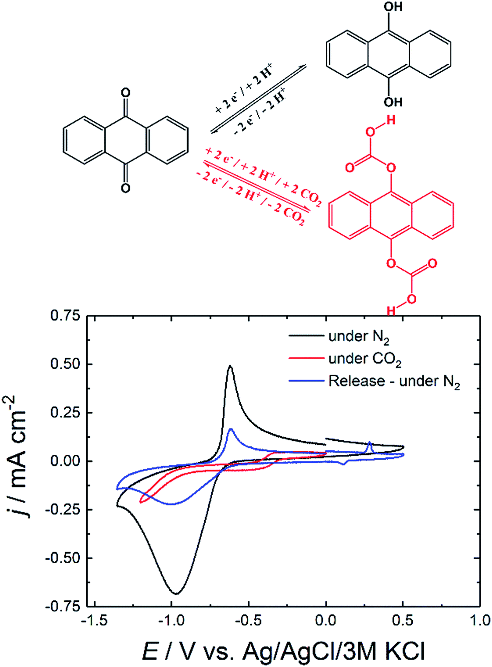 | ||
| Fig. 1 CV curves of AQ on glassy carbon (GC) under different gas-saturated conditions. | ||
The initial nitrogen (N2) saturated conditions in Fig. 1 show a quasi-reversible reduction feature at −0.80 V which is in accordance to homogenous reduction of anthracene-9,10-diol (hydroquinone) structure reported in literature.24–26 Under CO2 saturated conditions the electrochemical response of AQ nearly vanished and only very low current was observed upon further reduction.
After removal of unbound CO2 out of the system and saturation of the solution with N2 followed by electrochemical oxidation gave rise to a small oxidation peak at +0.27 V which was assigned to the release of carbon dioxide. Afterwards, cycling further to negative potentials reveals once more characteristic quasi-reversible reductive feature of AQ. The significant decrease in current density from initial −0.68 to −0.22 mA cm−2 after release could be explained by the dissolution of the soluble hydroquinone species from the electrode.
The vanishing of the reductive peaks behavior was already reported for different carbonyl bearing pigments in literature.18,19 Like in the previous system we assigned this to the in situ formation of a carbonate-like structure illustrated in Fig. 1.
In further experiments not only glassy carbon was used as electrode material but also thin-layers of chromium and gold (Cr–Au) on glass substrates. The CV of AQ/Cr–Au/glass is shown in Fig. 2 in order to confirm the similarity to the CV of AQ/glassy carbon. Furthermore, the comparison of the first and the second cycle under CO2 is shown in the same graph.
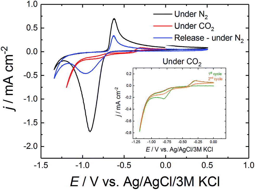 | ||
| Fig. 2 Cyclic voltammetry of AQ/Cr–Au/glass in 0.1 M Na2SO4. The insert shows the comparison of the first and the second cycle of CV under CO2. | ||
Comparing the curves of AQ/Cr–Au in Fig. 2 to the ones of AQ/GC in Fig. 1 revealed a nearly identical shape. The only difference was the lack of the small oxidative release peak at +0.27 V. To the best of our knowledge, this might be due to the fact that glassy carbon possesses a different surface structure than gold. We observe, that on gold a rearrangement of the AQ was taking place which caused the lack of this peak (Fig. 3).
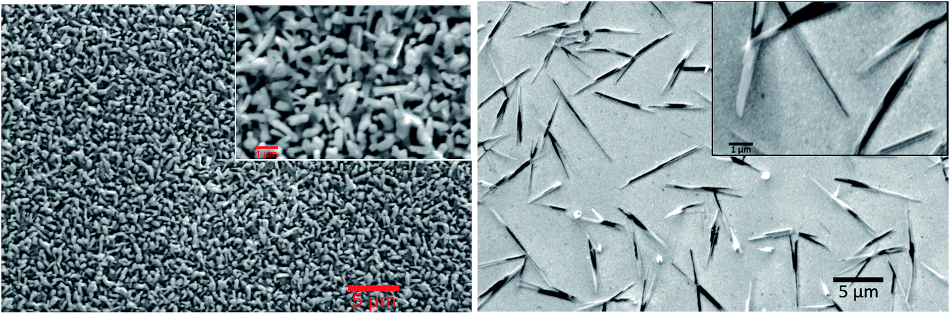 | ||
| Fig. 3 Scanning electron microscopy (SEM) images of the pristine anthraquinone film on Cr–Au on glass (left) and after electrochemical CO2 capture and release (right). | ||
As discussed before, initially the AQ is reduced forming nucleophilic hydroquinone structure which is then presumed to bind CO2.13,14,16 This theory was supported by comparing the first CV cycle under CO2 with the second one in the inset of Fig. 2. The first cycle still showed the reductive peak of anthraquinone, which in the second cycle disappeared due the formation of the mentioned carbonate-like structure. Under those CO2 conditions, this flat CV behavior was observed over 50 cycles. Only after repurging the system with N2 and releasing CO2 by sweeping to the oxidative side, the reductive peak of anthraquinone was recovered again.
We have also observed physical changes on the crystal structure of AQ thin films. Fig. 3 shows SEM image of AQ film directly after evaporation (on the left) forming a quite uniform brick-like structure. Upon performing the electrochemical capture and release of carbon dioxide, needle-like microcrystals (Mikado-like) were observed (on the right).
Such recrystallization of carbonyl pigments has also already been reported.27,28 The reason for this was most probably the partial dissolving and recrystallization of AQ molecules during the process.
To further investigate and characterize the optical absorption changes, UV-vis spectroelectrochemistry experiments were conducted as shown in Fig. 4.
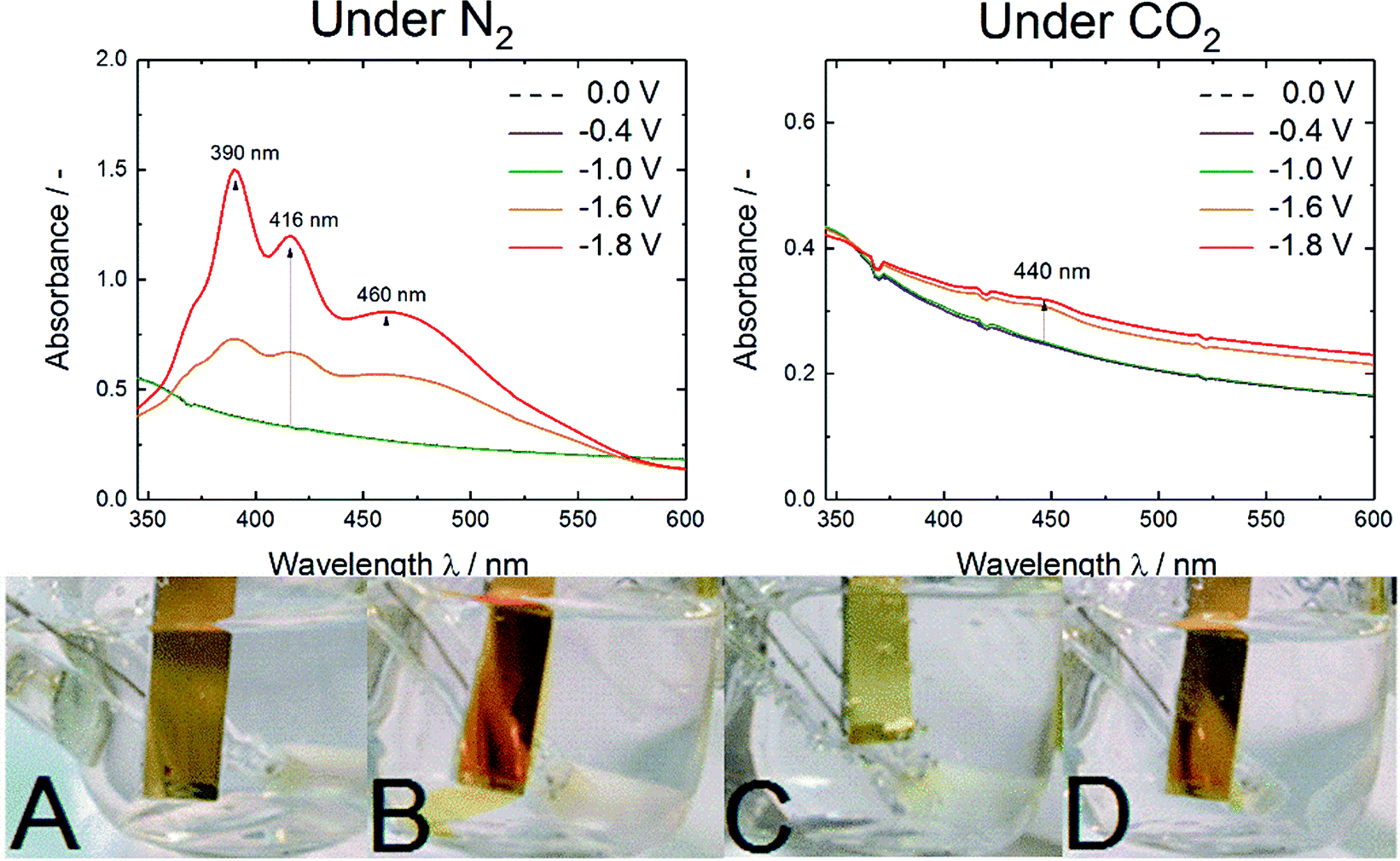 | ||
| Fig. 4 UV-vis spectra of AQ/FTO/glass electrodes under nitrogen saturated conditions (left) and under CO2 saturated conditions (right) at various potentials vs. Ag/AgCl. On the bottom pictures of AQ/Cr–Au/glass while performing CV are shown. (A) No potential applied, (B) at −1.0 V vs. Ag/AgCl/3 M KCl under N2, (C) at −1.0 V vs. Ag/AgCl/3 M KCl under CO2, (D) at −1.0 V vs. Ag/AgCl/3 M KCl after release under N2. | ||
The pictures A to D in Fig. 4 show the observed color changes upon electrochemistry on a Cr–Au electrode. Under electrochemical reduction under N2 saturated conditions (Fig. 4B and D) a color change to red-orange caused by the soluble anthracene-9,10-diol species was observed. Besides, under CO2-rich atmosphere (Fig. 4C) no dissolving process but a change to a brighter yellow species was observed.
These qualitative observations were justified by the UV-vis spectroelectrochemistry. Under N2 saturated conditions three strong absorption bands at 390, 416 and 460 nm were observed. According to Babaei et al. and Shamsipur et al. the three bands could be correlated to differently protonated anthracene-9,10-diol species whereas in this aqueous surrounding the presence of a radical species was very unlikely.25,26 The absorption maximum for AQ2− was reported at 466/470 nm and the one for AQH− at 412/414 nm. As they reported that protonation was causing a blueshift in absorption, the detected band at 390 nm could be assigned to the AQH2 species.25,26
In contrast, under CO2 saturated conditions the system was forming an absorption shoulder at 440 nm which was responsible for the brighter yellow color shown in Fig. 4C. To further substantiate the proposed anthraquinone–carbonate structure depicted in Fig. 1, in situ ATR-FTIR spectroelectrochemistry of AQ on a germanium (Ge) reflection element/electrode was conducted under CO2 conditions (N2 conditions shown in Fig. S2†). In Fig. 5 the characteristic region is zoomed in and the arising/disappearing bands were correlated with the molecular structural changes.
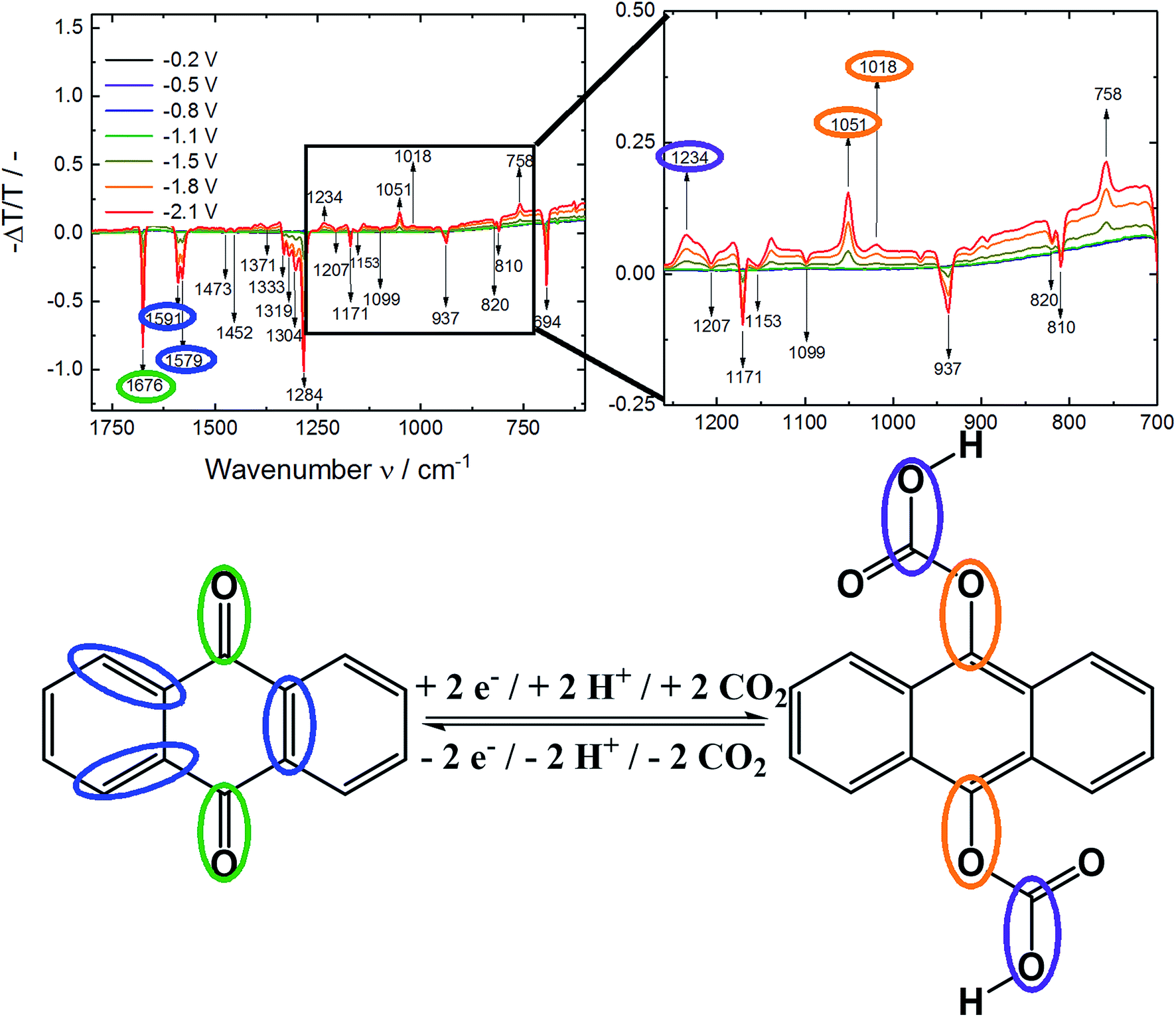 | ||
| Fig. 5 ATR-FTIR spectroelectrochemistry of AQ/Ge under CO2 saturated conditions at various potentials vs. Ag/AgCl (top). On the bottom the proposed structure of the anthraquinone–carbonate species with assignment of functional groups to the IR spectrum. | ||
In analogy to the IR spectrum under N2 saturated conditions (see ESI†) quite strong negative bands (disappearing of functional groups) were observed upon reductive dissolving of anthraquinone shown in Fig. 5. In order to compare the disappearing peaks with the material, ATR-IR powder spectra of anthracene and anthraquinone were measured, shown in Fig. 6.
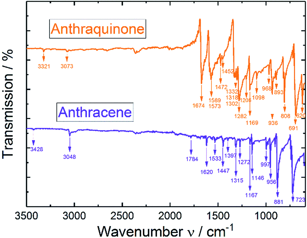 | ||
| Fig. 6 ATR-IR spectra of pure anthracene and anthraquinone powders. | ||
According to the ATR-IR powder spectra of anthraquinone and anthracene in Fig. 6 and from the examples in literature29 the disappearing peaks could fully be correlated to anthraquinone and the characteristic C![[double bond, length as m-dash]](https://www.rsc.org/images/entities/char_e001.gif) O bands, respectively.
O bands, respectively.
The fluctuations in the baseline of the measurements might arise from the air that is trapped within the powder.
The arising band at 1066 cm−1 under N2 conditions was a proof for Carom–O stretching vibration in the anthracene-9,10-diol structure.30 Under CO2 conditions two bands at 1051/1018 cm−1 indicated the formation of Carom–O single bonds.30 As those bands appeared at lower frequencies compared to nitrogen conditions, they were assumed to be caused by larger moieties attached to the oxygen atom. Also, a literature report from Criswell and Klanderman assigned bands in this wavenumber region from 960 to 1060 cm−1 to C–O bonds in comparable structures.31 In addition, the occurrence of the band at 1234 cm−1 was most likely caused by a C–O stretch of a carboxylic acid. Nyquist and Potts32 reported for asymmetric O–C–O stretches in proximity of an aromatic system values between 1211 and 1248 cm−1 which was also in accordance to Silverstein, Bassler and Morrill.30 Furthermore, Nyquist and Potts reported the existence of out-of-plane skeletal deformations at ∼800 cm−1, which we correlated to the rising peak at 758 cm−1.32
Under both, nitrogen and carbon dioxide, conditions a broad band at 3350 cm−1 from O–H bonds was appearing which did not allow differentiation between the phenolic and carboxylic O–H bond. Besides occurring of a C–O band from the carboxylic acid also the appearance of a CO band would be expected. Due to the high degree of dissolving during the experiment we assumed this evolving feature to be overlapping with the disappearing CO of the anthraquinone and other IR features in this region (according to Fig. 6).
Besides the different features of the evolving Carom–O under N2 and CO2 and the rise of bands at 1234 cm−1 and 758 cm−1 from the carboxylic acid underlined the formation of a new species upon electrochemical reduction of anthraquinone under CO2 saturated conditions.
In addition to investigations about the structural changes upon the carbon dioxide capture also the quantification of the CO2 capture process was studied. Assuming the possible uptake of 2 moles CO2 per anthraquinone molecule resulted in a theoretical uptake capacity of 9.6 mmolCO2 gAQ−1. Electrochemical capture and release experiments in triplicates resulted in an average experimental uptake capacity of 5.9 mmolCO2 gAQ−1, which referred to an efficiency of 61% (it was assumed that the detected and released amount was equal to the captured amount). As the efficiency was above 50% the assumption of capturing two moles CO2 per molecule anthraquinone in some parts of the electrode seemed to be plausible. This uptake capacity value was higher than the compounds reported previously by our group18,19 for electrochemical capture and release and comparable to the industrially-used capturing agent monoethanolamine.8 Those good capture and release features could be explained by a theory made-up in 1993 by DuBois et al.14 As the binding energy for CO2 could be related to the E1/2 of the quinone, a half-wave potential of −0.5 to −0.7 V vs. SCE was found to be optimum.14 Re-calculating the reduction of AQ resulted in a similar potential of −0.84 V vs. SCE.
4. Conclusions
In summary, we showed that the simple molecule anthraquinone is able to capture and release CO2 reversibly upon electrochemical reduction and re-oxidation exhibiting a high uptake capacity of 5.9 mmolCO2 gAQ−1. Although the material is dissolving over repetitive cycles under N2 conditions, it is relatively stable under CO2 upon formation of a carbonate-like structure. Experiments under CO2 at constant potential of −1.2 V for 60 minutes as well as for 50 CV cycles confirm this stability. To the best of our knowledge anthraquinone, such simple yet industrially significant molecule, is demonstrated for the first time for its capability of reversible heterogeneous electrochemical capture and release of CO2 in aqueous solutions under ambient pressure and temperature.If the CO2 capture and immobilization is successful on an electrode, the same electrode can be also functionalized with catalysts to make the electrochemical reduction of the captured CO2. This combination of capture with reduction of CO2 is our next level of work.
Conflicts of interest
The authors declare no competing interests.Acknowledgements
Authors gratefully acknowledge the funding of from FWF within the framework of Prof. Sariciftci's Wittgenstein Prize (Solare Energie Umwandlung Z222-N19) and the FFG within the project CO2 TRANSFER (848862). We kindly acknowledge the help of DI Halime Coskun Aljabour for introducing us to sublimation purification of anthraquinone. The help of Prof. Günther Knör and Dr Mariusz Wolff for conducting UV-vis measurements in their facilities is gratefully acknowledged.Notes and references
-
M. Aresta, Carbon Dioxide Recovery and Utilization, Springer Science+Business Media, Dordrecht, 2003 Search PubMed
.
-
M. Aresta, Carbon Dioxide as Chemical Feedstock, WILEY-VCH Verlag GmbH & Co. KGaA, Weinheim, 2010 Search PubMed
- M. Rakowski Dubois and D. L. Dubois, Acc. Chem. Res., 2009, 42, 1974–1982 CrossRef PubMed
- J. Ma, N. Sun, X. Zhang, N. Zhao, F. Xiao, W. Wei and Y. Sun, Catal. Today, 2009, 148, 221–231 CrossRef
- D. H. Apaydin, S. Schlager, E. Portenkirchner and N. S. Sariciftci, ChemPhysChem, 2017, 18, 3094–3116 CrossRef PubMed
-
S. Topham, A. Bazzanella, S. Schiebahn, S. Luhr, L. Zhao, A. Otto and D. Stolten, Ullmann's Encycl. Ind. Chem., 2014, pp. 1–43 Search PubMed
- G. T. Rochelle, Science, 2009, 325, 1652–1654 CrossRef PubMed
- T. Supap, R. Idem, P. Tontiwachwuthikul and C. Saiwan, Int. J. Greenhouse Gas Control, 2009, 3, 133–142 CrossRef
- X. Gui, Z. Tang and W. Fei, J. Chem. Eng. Data, 2011, 56, 2420–2429 CrossRef
- A. Rehman and S.-J. Park, Macromol. Res., 2017, 1035–1042 CrossRef
- J. Hu, Y. Liu, J. Liu, C. Gu and D. Wu, Microporous Mesoporous Mater., 2018, 256, 25–31 CrossRef
- J. Harada, Y. Sakakibara, A. Kunai and K. Sasaki, Bull. Chem. Soc. Jpn., 1984, 57, 611–612 CrossRef
- M. B. Mizen and M. S. Wrighton, J. Electrochem. Soc., 1989, 136, 941–946 CrossRef
-
D. L. DuBois, A. Miedaner, W. Bell and J. C. Smart, in Electrochemical and Electrocatalytic Reactions of Carbon Dioxide, ed. B. P. Sullivan, K. Kristl and H. E. Guard, Elsevier Science Publishers B. V., Amsterdam, 1993, pp. 94–117 Search PubMed
- P. Scovazzo, J. Poshusta, D. DuBois, C. Koval and R. Noble, J. Electrochem. Soc., 2003, 150, D91 CrossRef
- B. Gurkan, F. Simeon and T. A. Hatton, ACS Sustainable Chem. Eng., 2015, 3, 1394–1405 CrossRef
- W. Yin, A. Grimaud, I. Azcarate, C. Yang and J.-M. Tarascon, J. Phys. Chem. C, 2018, 122, 6546–6554 CrossRef
- D. H. Apaydin, E. D. Głowacki, E. Portenkirchner and N. S. Sariciftci, Angew. Chem., Int. Ed., 2014, 53, 6819–6822 CrossRef PubMed
- D. H. Apaydin, M. Gora, E. Portenkirchner, K. T. Oppelt, H. Neugebauer, M. Jakesova, E. D. Głowacki, J. Kunze-Liebhäuser, M. Zagorska, J. Mieczkowski and N. S. Sariciftci, ACS Appl. Mater. Interfaces, 2017, 9, 12919–12923 CrossRef PubMed
- H. Ishida, T. Ohba, T. Yamaguchi and K. Ohkubo, Chem. Lett., 1994, 23, 905–908 CrossRef
- R. Ranjan, J. Olson, P. Singh, E. D. Lorance, D. A. Buttry and I. R. Gould, J. Phys. Chem. Lett., 2015, 6, 4943–4946 CrossRef PubMed
- P. Singh, J. H. Rheinhardt, J. Z. Olson, P. Tarakeshwar, V. Mujica and D. A. Buttry, J. Am. Chem. Soc., 2017, 139, 1033–1036 CrossRef PubMed
- C. Liu and K. Landskron, Chem. Commun., 2017, 53, 3661–3664 RSC
- J. Revenga, F. Rodríguez and J. Tijero, J. Electrochem. Soc., 1994, 141, 330–333 CrossRef
- A. Babaei, P. A. Connor, A. J. McQuillan and S. Umapathy, J. Chem. Educ., 1997, 74, 1200–1204 CrossRef
- M. Shamsipur, B. Hemmateenejad, A. Babaei and L. Faraj-Sharabiani, J. Electroanal. Chem., 2004, 570, 227–234 CrossRef
- M. Jakesova, D. H. Apaydin, M. Sytnyk, K. T. Oppelt, W. Heiss, N. S. Sariciftci and E. D. Głowacki, Adv. Funct. Mater., 2016, 26, 5248–5254 CrossRef
- J. Danziger, N. R. Armstrong and J. P. Dodelet, Chem. Mater., 1991, 3, 812–820 CrossRef
- National Institute of Advanced Industrial Science and Technology, http://sdbs.db.aist.go.jp, accessed 21 December 2017.
-
R. M. Silverstein, G. C. Bassler and T. C. Morrill, Spectrometric identification of organic compounds, New York, 5th edn, 1991 Search PubMed
- T. R. Criswell and B. H. Klanderman, J. Org. Chem., 1974, 39, 770–774 CrossRef
- R. A. Nyquist and W. J. Potts, Spectrochim. Acta, 1961, 17, 679–697 CrossRef
Footnote |
| † Electronic supplementary information (ESI) available. See DOI: 10.1039/c8ta04817g |
| This journal is © The Royal Society of Chemistry 2018 |