
 Open Access Article
 This Open Access Article is licensed under a
 Creative Commons Attribution 3.0 Unported Licence
Alginic acid-derived mesoporous carbon (Starbon®) as template and reducing agent for the hydrothermal synthesis of mesoporous LiMn2O4 grafted with carbonaceous species†
Sanghoon
Kim
 a,
Mario
De bruyn‡
b,
Johan G.
Alauzun
a,
Nicolas
Louvain
ac,
Nicolas
Brun
a,
Duncan J.
Macquarrie
b,
Lorenzo
Stievano
ac,
Bruno
Boury
a,
Laure
Monconduit
ac and
P. Hubert
Mutin
*a
a,
Mario
De bruyn‡
b,
Johan G.
Alauzun
a,
Nicolas
Louvain
ac,
Nicolas
Brun
a,
Duncan J.
Macquarrie
b,
Lorenzo
Stievano
ac,
Bruno
Boury
a,
Laure
Monconduit
ac and
P. Hubert
Mutin
*a
aInstitut Charles Gerhardt Montpellier, Université de Montpellier, CNRS, Montpellier, France. E-mail: hubert.mutin@umontpellier.fr
bGreen Chemistry Centre of Excellence, University of York, York, North Yorkshire YO10 5DD, UK
cRéseau sur le Stockage Electrochimique de l'Energie (RS2E), CNRS FR3459, 33 Rue Saint Leu, 80039 Amiens Cedex, France
First published on 3rd July 2018
Abstract
An alginic acid-derived mesoporous carbonaceous material (Starbon® A300) was used as a sacrificial porous template providing both a reducing environment and anchoring sites for LMO precursors, KMnO4 and LiOH. After hydrothermal treatment at 180 °C for 24 h, the resulting nanocrystalline LMO particles (≈40 nm) spontaneously aggregated, generating a mesoporous structure with a relatively high mesopore volume (≈0.33 cm3 g−1) and large pore size (≈30 nm). Moreover, a small amount (≈0.6 wt%) of residual carbon was present in this mesoporous LMO. This carbon, which arises from carbonaceous species grafted at the surface of the LMO nanoparticles, was found to significantly enhance the rate capability of LMO by reducing the internal electronic resistance. Finally, a “green” LMO electrode formulated using this Starbon-derived LMO as an active material, Starbon® A800 as a conductive additive and sodium alginate as a binder was tested, showing promising electrochemical performance.
Introduction
Spinel LiMn2O4 (LMO) has been considered as one of the most promising positive electrode materials in Li ion batteries for high power applications such as electric vehicles or portable electronic devices, owing to its low cost, low toxicity and to the high abundance of manganese.1–6 However, practical implementation of LMO technology is hampered by a low rate capability and fading of its capacity during cycling, mainly due to the dissolution of manganese in the electrolyte7–9 and to the phase transition from the cubic spinel to a tetragonal crystal structure caused by Jahn–Teller distortion.10,11 Over the years, many efforts have been made to address these problems, including doping,12–14 carbon coating,15,16 and nanostructuring of LMO.17–22 Nano-structuration leading to mesoporous LMO materials has been shown to enhance the battery performance, due to the large surface area favoring better interfacial contact between electrode and electrolyte,23–27 and to the fast lithium ion diffusion through the mesopores. The mesoporous LMO materials can be generally synthesized via solid-state reaction of pre-synthesized porous magnesium oxide with a lithium precursor, which implies a heat treatment at temperatures generally above 500 °C,23,28 or reduction of KMnO4 to manganese oxide in aqueous solution, followed by lithiation under mild hydrothermal conditions (<200 °C).29,30 The latter method has been widely investigated using various reducing agents, of essentially two types (i) molecular or polymeric organic reducing agent such as glucose31 or (ii) conductive carbon materials such as carbon nanotube or graphene to obtain a carbon/LMO hybrid electrode. Even though the hydrothermal synthesis seems versatile for the synthesis of mesoporous LMO, it bears also a few disadvantages, the main ones lying in the difficulty of controlling morphology and porosity of LMO for the first type of reducing agent, and in the high cost of carbon nanotubes or graphene for the second type.32–34 The use of a low-cost porous carbon as both structure directing and reducing agent for KMnO4 might offer an interesting alternative for the synthesis of porous LMO. However, to the best of our knowledge, this strategy remains nearly unexplored, with the exception of one paper in which carbon fiber paper was used as a structure directing template.35Environmental issues being of increasing concern, the green synthesis of porous carbonaceous materials has intensively been investigated, using for example, sustainable or biomass materials such as wheat flour,36 sugar from Coca Cola®,37 or soft templating method using polymeric species.38,39 Among various ‘green’ carbonaceous materials, Starbon® are a unique class of bio-derived mesoporous carbonaceous materials, which can be derived from a range of polysaccharides by means of a template-free pyrolysis.40–42 The physicochemical properties of Starbon®, including its porosity, the hydrophobicity/hydrophilicity ratio of the surface and their conductivity, can be easily tuned by varying the parameters of said thermal transformation, and most notably the type of polysaccharide involved and the pyrolysis temperature. Starbon® materials have been applied as catalysts,43,44 sorbents for pollutant removal45–47 and as catalyst supports.48 In the field of electrochemistry, Starbon® materials have found use as an alternative carbon additive in Li-ion batteries, significantly improving battery performance compared to conventional carbon additives.49
We report here the hydrothermal synthesis of mesoporous nanocrystalline LMO using an alginic acid-derived mesoporous carbonaceous materials (Starbon®) as both a sacrificial porous template and a reducing environment that also provides anchoring sites for the precursors of LMO, KMnO4 and LiOH. The resulting well-crystallized LMO nanoparticles of 30–50 nm in size spontaneously aggregate, generating a mesoporous network. Interestingly, a small amount of residual carbonaceous species (≈0.6 wt% C) remains grafted at the surface of the LMO nanoparticles, and this residual carbon significantly enhances the rate capability of mesoporous LMO by reducing its internal electronic resistance.
Finally, as a proof of concept of a “green” electrode derived from seaweed, an electrode formulated with this mesoporous LMO as active material, alginic acid derived Starbon® as a conductive additive and alginic acid sodium salt as a binder was tested, showing an electrochemical performance comparable to conventional LMO electrodes.
Experimental
Materials
Alginic acid and potassium permanganate (KMnO4, >99%) were purchased from Sigma-Aldrich (France). Alginic acid sodium salt was purchased from Acros (France). Super P (>99%) and lithium hydroxide (LiOH, anhydrous, 99%) were purchased from Alfa Aesar (France). S300 was prepared at the University of York and is similar to the mesoporous carbon Starbon® 300 commercialized by Sigma-Aldrich (reference number: 702110). A commercial bulk lithium manganese oxide (LiMn2O4) with particle size around 200–400 nm was purchased from Targray (Canada). All reagents were used without further purification.Synthesis of alginic acid-derived mesoporous carbon materials
First, a dried expanded mesoporous gel of alginic acid was prepared as described previously.50 Briefly, an alginic acid solution (4.8 wt% in water) was gelled by heating at 90 °C for 2.5 h, and then kept at 4 °C for 24 h. Afterwards, tert-butyl alcohol (TBA) was added to the gel, to reach the eutectic composition (30 wt% TBA, 70 wt% water). The mixture was stirred for 1 h at RT and then kept for 24 h without stirring and finally freeze-dried (−55 °C). The so-obtained dried expanded gel of alginic acid obtained in this way was then pyrolyzed at 300 °C for 3 h (argon flow: 50 mL min−1, heating rate: 1 °C min−1) giving the mesoporous carbonaceous material A300 (A stands for alginic acid, 300 for the carbonization temperature in °C) with a yield of ca. 40 wt%. The specific surface area and total pore volume of A300 determined by N2 physisorption experiments were 222 m2 g−1 and 1.04 cm3 g−1, respectively.Other Starbon® materials such as A450 and A800 were obtained by carbonization for 3 hours of the expanded gel of alginic acid at 450 °C and 800 °C, respectively.
Synthesis of mesoporous nanocrystalline LiMn2O4 using A300
Briefly, KMnO4 (316 mg, 2 mmol) was dissolved in a suspension of A300 (50 mg, 36 mg as carbon, 3 mmol) dispersed in 21 mL of water and stirred for 2 h at RT. Then, a 1 M aqueous solution of LiOH (4 mL, 4 mmol) was added and the suspension was stirred for 1 h at RT. The resulting mixture was transferred into an autoclave with polytetrafluoroethylene (PTFE) lining (100 mL). The sealed autoclave was heated at 180 °C in an oven for 24 h under autogenous pressure. After cooling the resulting powder was centrifuged, then washed 3 times with water (50 mL), dried under vacuum at 120 °C for 15 h, yielding mesoporous LiMn2O4 (labeled LMO-HT) with the molar yield of 77% calculated from the amount of KMnO4 initially introduced. Several fractions of LMO-HT were then calcined at 350, 500, or 700 °C in a muffle furnace (heating rate: 1 °C min−1) giving respectively LMO-350, LMO-500, or LMO-700.Characterization
Powder XRD patterns were measured using a PANalytical X'Pert Pro MPD diffractometer, equipped with the Kα radiation of Cu (λ = 1.5418 Å) and a step size of 0.033° in the 10–80° 2θ range. N2 physisorption experiments were carried out at −196 °C on a Micromeritics 3Flex; all materials were degassed at 120 °C for 15 h at 5 × 10⁻² mbar before the physisorption measurements. ICP-OES analysis was performed using an iCAP 6000 Series. Scanning electron microscopy (SEM) images were acquired with a Hitachi S-4800 electron microscope. EDX analyses were acquired with a JEOL CENTURIO detector. Transmission electron microscopy (TEM) images were acquired using JEOL FX2200 microscope. Raman spectra were obtained on a Horiba Jobin-Yvon LabRAM ARAMIS microspectrometer. The excitation wavelength was 633 nm.Galvanostatic electrochemical characterizations were performed at room temperature on a BTS3000 instrument from Neware Battery. Electrochemical impedance spectroscopy (EIS) studies were done on a BioLogic VSP instrument, from 100 kHz to 20 mHz, with a 10 mV amplitude in potentiostatic mode. LMO electrodes are composed of the active material (82 wt%), Super P (12 wt%), and polyvinylidene fluoride (PVDF, 6 wt%, Solef 5130). After stirring in N-methyl-2-pyrrolidone (NMP), the slurry was mixed using an agate grinding jar (1 h at 500 rpm), then tape casted uniformly at 150 μm onto an aluminum current collector (0.018 mm, 99.0%, Goodfellow) using a 3540 bird film applicator from Elcometer. In case of the green LMO electrode formulated with Starbon® A800 as alternative carbon additive and alginic acid sodium salt as alternative binder, the weight ratio is 78![[thin space (1/6-em)]](https://www.rsc.org/images/entities/char_2009.gif) :12:10 for active material:A800:alginic acid sodium salt, respectively. For the slurry preparation of the green LMO electrode, water was used instead of NMP. Electrodes (diameter 12.7 mm) were then cut out with a disk cutter and dried under vacuum at 90 °C for 15 h. The loading weight per electrode disk was approximatively 2.2 mg. CR2032 coin-type cells were assembled in a glove box under Ar atmosphere (O2 < 0.5 ppm, H2O < 0.5 ppm), using lithium metal as both reference and counter electrode. The electrolyte was LP30 (1.0 M LiPF6 in ethylene carbonate (EC)/dimethyl carbonate (DMC) = 50/50 (v/v)). Whatman glass fibre disks were used as separators. The electrochemical galvanostatic measurements were taken in the voltage range of 3.4–4.3 V versus Li+/Li at different current densities.
:12:10 for active material:A800:alginic acid sodium salt, respectively. For the slurry preparation of the green LMO electrode, water was used instead of NMP. Electrodes (diameter 12.7 mm) were then cut out with a disk cutter and dried under vacuum at 90 °C for 15 h. The loading weight per electrode disk was approximatively 2.2 mg. CR2032 coin-type cells were assembled in a glove box under Ar atmosphere (O2 < 0.5 ppm, H2O < 0.5 ppm), using lithium metal as both reference and counter electrode. The electrolyte was LP30 (1.0 M LiPF6 in ethylene carbonate (EC)/dimethyl carbonate (DMC) = 50/50 (v/v)). Whatman glass fibre disks were used as separators. The electrochemical galvanostatic measurements were taken in the voltage range of 3.4–4.3 V versus Li+/Li at different current densities.
Results and discussion
Synthesis of mesoporous nanocrystalline LMO materials
The Starbon A300 template was prepared by pyrolysis at 300 °C of a mesoporous expanded cryogel of alginic acid, as previously reported.37 The key synthetic step to maintain the mesoporous structure of alginic acid gel during solvent removal by freeze-drying is adding tert-butyl alcohol to form a water/tert-butyl alcohol eutectic.50 As shown in Fig. S1,† direct freeze-drying without addition of tert-butyl alcohol yields a cryogel with only 0.36 cm3 g−1 as mesopores volume, 3 times lower than the cryogel obtained with the water/tert-butyl alcohol eutectic.This mesoporous carbonaceous material A300 was used successfully as sacrificial template and reducing agent in the hydrothermal synthesis of mesoporous nanocrystalline LiMn2O4 (LMO-HT). The method is simple: in a first step, an aqueous dispersion of A300 is reacted for 2 h at room temperature with KMnO4 to form MnO2 then LiOH is added and the mixture heated at 180 °C for 24 h under autogenous pressure to perform the lithiation of MnO2.
Controlling the phase purity is a recurrent issue in the hydrothermal synthesis of LMO and a precise control of both Li/Mn and C/Mn molar ratio is essential to obtain pure LMO. As shown in Fig. S2,† the ratio of LiOH/KMnO4 was systematically varied, and a 2:1 ratio was found to lead to pure LMO. As detailed in Fig. S3,† the optimum amount of A300 is 50 mg for 2 mmol of KMnO4, corresponding to a C/Mn molar ratio of 1.5. The nature of the carbonaceous material was also found to be important: interestingly, pure LMO could be obtained only using A300, while additional phases are detected when the synthesis is performed under the same conditions but using different carbon materials (Fig. S3†): alginic acid, expanded alginic acid calcined at higher temperatures (A450, A800), expanded starch carbonized at 300 °C (S300), or carbon black (Super P). These results suggest that both the mesoporous texture and the numerous residual carboxylic acid groups found in A300 play an important role in our synthesis.
According to CHNS elemental analysis, LMO-HT contains only 0.6 wt% of carbon. This value is significantly lower than the theoretical value of 9 wt% which can be calculated from the stoichiometry of the reduction of KMnO4 with carbon to form MnO2:
| 4MnO4− + 3C → 4MnO2 + CO32− + 2HCO3− |
When the reaction of A300 with KMnO4 was stopped after 2 h (i.e., before the hydrothermal treatment) the violet colour of the suspension had vanished, indicating complete reduction of KMnO4. Characterization of the dried resulting powder shows the formation of a poorly crystalline, mesoporous manganese oxide with a carbon content close to 9 wt% (Fig. S4†). Hence, it can be concluded that A300 served during the first step as both the reducing agent and the mesoporous template, and that most of the A300 was then removed during the hydrothermal lithiation treatment. The low stability of A300 under hydrothermal conditions in the presence of LiOH is not surprising as this material is only very partially carbonized, with a C:O molar ratio of 4:1.41
The optimized LMO material (LMO-HT) was then calcined at 350, 500 or 700 °C in air, giving LMO-350, LMO-500 or LMO-700, respectively, allowing the investigation of the influence of carbon content and texture on the electrochemical performance. Calcination at 500 °C led to a virtually complete removal of residual organics (0.04 wt% C in LMO-500 sample).
Fig. 1 shows the XRD patterns of LMO-HT and of the calcined samples compared with a commercial bulk LMO (LMO-Comm). All XRD patterns show only diffraction peaks characteristic of the cubic spinel structure of LiMn2O4 (JCPDS no. 49-0207) at 2θ = 18.6°, 36.1°, 37.7°, 43.9°, 48.1°, 58.3°, 64.0° and 67.4° corresponding to the (111), (311), (222), (400), (331), (333), (440) and (531) reflections, respectively. The chemical composition of LMO-HT was found to be Li0.99Mn1.00O4 by ICP analysis, thus, LMO-HT can be considered as a virtually stoichiometric LiMn2O4. Upon calcination, the peak corresponding to (111) plane slightly shifts towards lower 2θ, indicating an increase of the cell parameter a (Fig. S5, Table S1†). This increase of cell parameter can be explained considering that at low calcination temperatures the manganese ions in LMO are more stable as Mn4+ (0.054 nm), which is smaller than Mn3+ (0.064 nm).51,52 No other diffraction peaks characteristic of impurities such as α- or β-MnO2 (i.e., intense peak at 2θ = 28° for (310) or (110) plane of α or β-MnO2, respectively53) are observed. The LMO crystallite size, estimated using the Scherrer equation, increase slightly with the calcination temperature (Table 1).
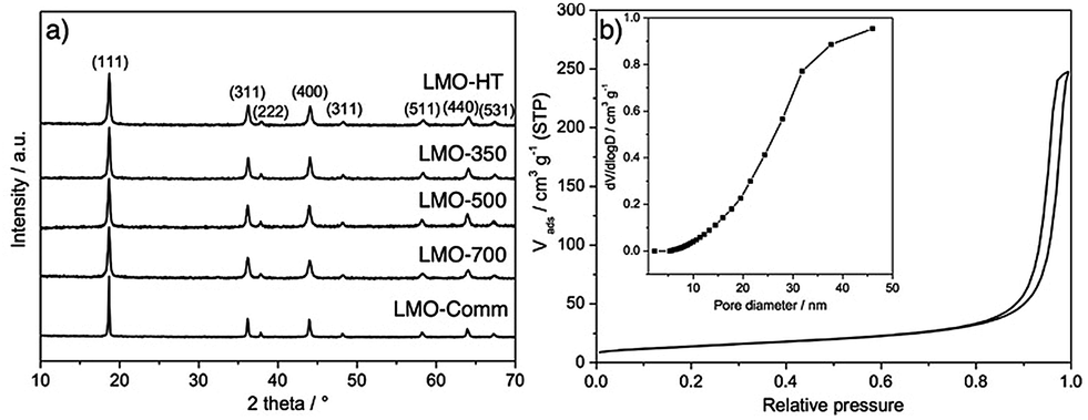 | ||
| Fig. 1 (a) Powder X-ray diffraction (XRD) patterns of LMO-HT, LMO-350, LMO-500, LMO-700 and LMO-Comm. (b) N2 adsorption–desorption isotherms and pore size distribution (inset) of LMO-HT. | ||
| S BET (m2 g−1) | PVtotalb (cm3 g−1) | PVmesoc (cm3 g−1) | D p (nm) | Crystallite sizee (nm) | |
|---|---|---|---|---|---|
| a Specific area determined by BET method. b Total pore volume at P/P0 = 0.99. c BJH mesopore volume between 2 and 50 nm. d BJH average mesopore diameter (desorption branch). e Derived from (111) reflection using the Scherrer equation. | |||||
| LMO-HT | 49 | 0.37 | 0.33 | 24 | 25 |
| LMO-350 | 50 | 0.32 | 0.28 | 23 | 28 |
| LMO-500 | 41 | 0.28 | 0.26 | 23 | 30 |
| LMO-700 | 17 | 0.11 | 0.11 | 23 | 33 |
| LMO-Comm | <1 | <0.01 | <0.01 | — | 60 |
The textural properties of LMO materials were evaluated by N2 physisorption (Fig. 1b for LMO-HT and Fig. S6† for the others). As shown in Table 1, LMO-HT is mesoporous, with a specific surface area of 49 m2 g−1 and a pore volume of 0.33 cm3 g−1. Both specific surface area and pore volume slightly decrease upon calcination up to 500 °C, owing to the growth of the LMO crystallites. Upon calcination at 700 °C, the strong decrease of surface area and pore volume can be ascribed mostly to the sintering of LMO particles.
Fig. 2 shows SEM images of samples LMO-HT, LMO-350, LMO-500, LMO-700 and commercial LMO. LMO-HT (Fig. 2a and b) is composed of aggregated nanoparticles giving rise to interparticle mesoporosity. The size of the LMO nanoparticles does not vary significantly upon calcination. However, sintering of LMO nanoparticles leading to a collapse of the mesoporosity was evidenced for LMO-700 (Fig. S7†).
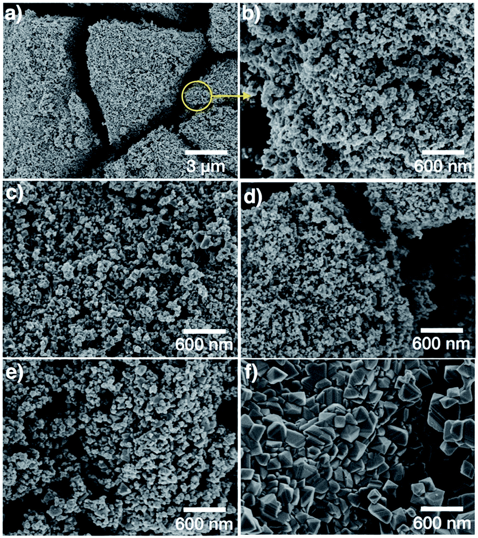 | ||
| Fig. 2 SEM images of (a), (b) LMO-HT, (c) LMO-350, (d) LMO-500, (e) LMO-700 and (f) LMO-Comm. More SEM images in Fig. S7.† | ||
TEM images of LMO-HT (Fig. 3) confirm that the mesoporosity derives from the random packing of well-crystallized primary LMO nanoparticles. In the case of LMO-HT (0.6 wt% C), TEM-EDX mapping reveals that the carbon is homogeneously distributed over the surface of the LMO particles. The average thickness of a carbon coating (estimated from the specific surface area of LMO-HT assuming a density of 1 for the coating) would be only ≈0.112 nm. Accordingly, the decomposition of A300 during the hydrothermal treatment does not lead to a “thick” carbon coating but rather to grafted molecular or macromolecular carbonaceous species which could not be removed by washing. The Raman spectrum of LMO-HT suggests the absence of graphitic structures in the residual organic species found in this sample (Fig. S8†), which is not surprising considering the low temperature used in the hydrothermal treatment (180 °C).
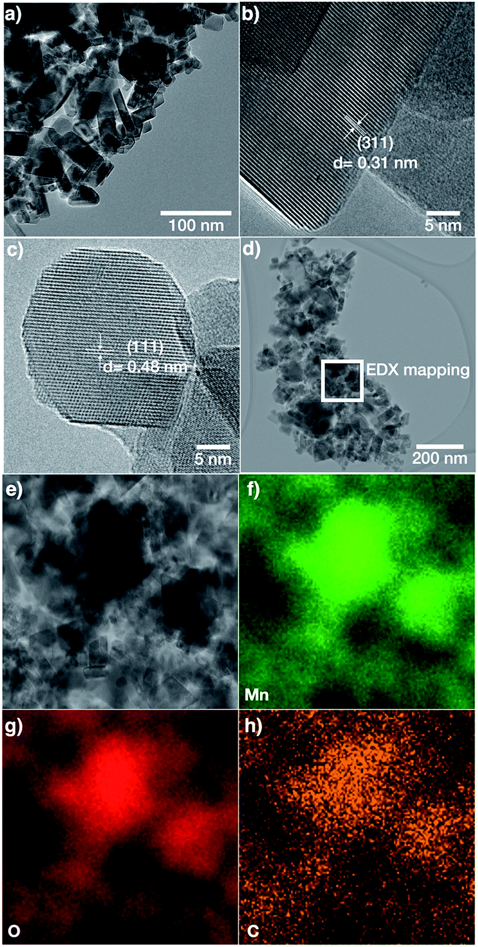 | ||
| Fig. 3 TEM images (a–d) and EDX mapping images for Mn, O and C (e–h) of LMO-HT. | ||
Even though the amount of these carbonaceous species is quite low, their role seems particularly important since they are found to significantly improve the electrochemical performance of mesoporous LMO (vide infra).
Electrochemical performance of mesoporous LMO materials
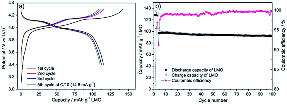
The electrochemical performance of LMO materials was evaluated in CR2032 coin-type half-cells using Li metal as counter and reference electrode. Fig. 4a shows representative charge/discharge galvanostatic curves of mesoporous LMO-HT at C-rate of C/10 (1C = 148 mA g−1 for LMO) over the voltage range of 3.4–4.3 V. The double plateau signature typical of LMO is observed, corresponding to a two-step process during both charge and discharge: the biphasic reaction between LiMn2O4 and Li0.5Mn2O4 at ≈4.0 V vs. Li/Li+ is followed by the biphasic reaction between Li0.5Mn2O4 and γ-MnO2 at ≈4.1 vs. Li/Li+.6 The initial charge and discharge capacities of mesoporous LMO-HT are 151 and 133 mA h g−1, respectively, with a low coulombic efficiency of 87%. This irreversible capacity at the 1st cycle is most probably due to the decomposition of the electrolyte at the surface of the electrode at high potential, leading to the formation of a solid electrolyte interphase (SEI).54 When higher C-rates are applied (from 0.5C to 10C), the characteristic double plateau becomes less visible along with a decrease of discharge capacity and an increase of the polarization (Fig. 4b).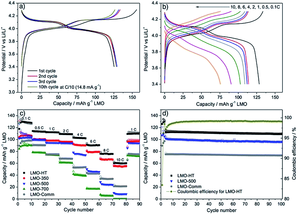 | ||
| Fig. 4 Galvanostatic charge–discharge curves for LMO-HT cycled (a) at C/10 (1st to 10th cycle), (b) at various C-rates (0.1–10C); (c) rate-capability and cycling performance of different LMO electrodes; (d) long term cyclability of different LMO electrodes at 1C for 100 cycles. First 3 cycles were tested at 0.1C. See Fig. S9† for galvanostatic charge–discharge curves for LMO-350, LMO-500, LMO-700 and LMO-Comm. | ||
LMO-HT delivers a much higher capacity than LMO-500, LMO-700 or LMO-Comm samples, particularly at high C rates, as shown in Fig. 4c. Calcination of LMO-HT at 500 °C leading to LMO-500 does not induce a significant modification of the crystallinity or of the texture, but mainly results in the removal of the residual carbonaceous species (<0.05 wt% C in LMO-500). Thus, it can be assumed that the presence of the carbonaceous species in LMO-HT are responsible for its remarkably improved electrochemical performance compared to LMO-500, probably by ensuring a good conductivity via interconnection of the LMO nanoparticles. Besides, the poor performance of LMO-700 can be ascribed to the sintering of the LMO particles upon calcination at 700 °C. The initial coulombic efficiency for LMO-350, 500, 700 and LMO-Comm were 80, 79, 66 and 64%, significantly lower than that of LMO-HT (89%).
Comparison between LMO-500 and LMO-Comm electrodes allows us to evaluate the role of the texture and particle size in the electrochemical behavior. At low to moderate C-rates (up to 4C), the mesoporous LMO-500 active material shows a much higher capacity than the non-porous LMO-Comm. This can be ascribed to the much higher specific surface area of LMO-500 leading to a better interfacial contact between electrode and electrolyte and to the fast lithium ion diffusion through the mesopores.23–27 On the other hand, at very high C-rates (above 4C), the situation is reversed and the LMO-Comm material displays a higher capacity than LMO-500. This behavior suggests that at very high C-rates the limiting factor becomes the electronic conductivity and that the small crystallite size in LMO-500 lead to a lower electronic conductivity than in LMO-Comm, possibly due to the drastic increase in the number of contacts between LMO nanoparticles (Fig. S10†).
Electrochemical impedance spectroscopy (EIS) was used to comfort this hypothesis. As shown in Fig. 5, the Nyquist plot for the different electrodes exhibits a single semicircle in the middle to high frequency range, which is attributed to the charge transfer resistance (Rct) between electrolyte and LMO. Before cycling, Rct for LMO-HT (76 Ω) and LMO-500 (93 Ω) is significantly lower than for LMO-Comm (163 Ω). After the first cycle, these values increase for all electrodes, most probably due to the formation of a solid electrolyte interphase (SEI) at the surface of the LMO particles. Upon further cycling this resistance remains then almost constant, indicating that the SEI layer of both electrodes is relatively stable over cycling, allowing stable electrode processes and good cycling performance.
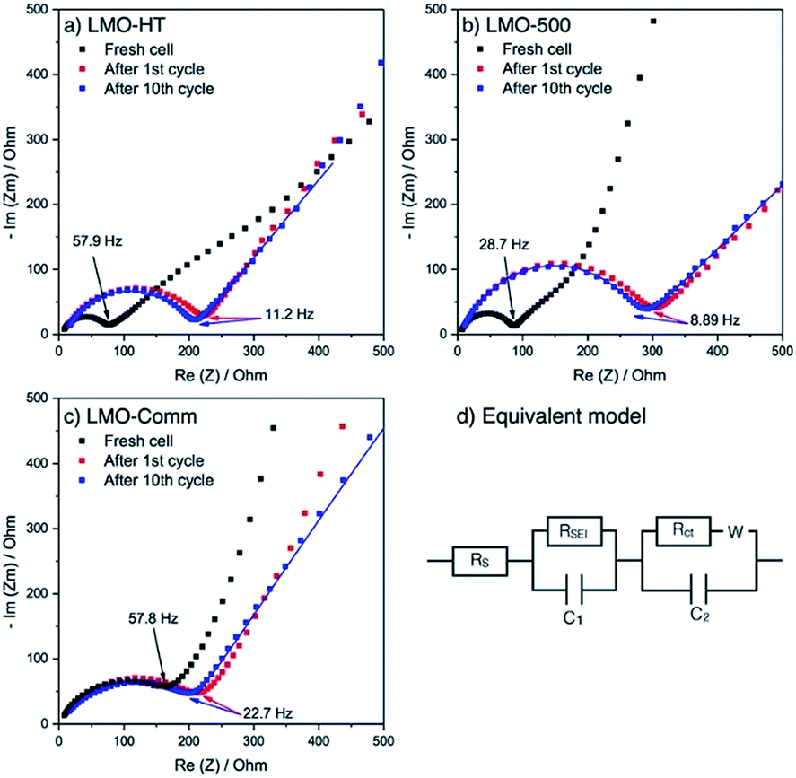 | ||
| Fig. 5 Nyquist plots of (a) LMO-HT electrode, (b) LMO-500 electrode, (c) LMO-Comm electrode during cycling at C/10, and (d) equivalent circuit model used. Fitting was performed on the Nyquist plots after 10th cycle and presented as solid line. | ||
The diffusion coefficient of Li ions (DLi+) was estimated by fitting the different plots on low frequency range. Interestingly, the DLi+ values for LMO-HT (3.2 × 10⁻¹² cm2 s−1) and LMO-500 (2.3 × 10⁻¹² cm2 s−1) are similar, while the value found for LMO-Comm (1.6 × 10⁻¹³ cm2 s−1) is significantly lower. The slower diffusion of Li ions in the non-porous commercial sample can be ascribed to the larger particle size.
Thus, the better performance at high C rate of LMO-Comm compared to LMO-500 cannot be attributed to improved Li ion diffusion or better charge transfer, but probably depends upon the higher electronic conductivity of LMO-Comm, due to the larger particle size in this sample.
Similarly, the superior behavior of LMO-HT compared to LMO-Comm can be ascribed at moderate C rates to its mesoporosity and at high C rates to the low amount of grafted carbonaceous species which efficiently increases electronic conductivity by bridging LMO nanoparticles.
The cycling performance of mesoporous LMO-HT, LMO-500 and LMO-Comm electrodes are compared in Fig. 4d. After 100 cycles at 1C, LMO-HT shows a discharge capacity of 112 mA h g−1, corresponding to 98.5% of the initial discharge capacity, thus demonstrating an excellent cycling stability (0.015% of fading per cycle). A coulombic efficiency of 99.2% is found after 100 cycles. Despite their decent electrochemical performance LMO-500 and LMO-Comm exhibit significantly lower capacities (94 and 77 mA h g−1 respectively) and lower capacity retentions after 100 cycles (96.2% and 94.5, respectively). Moreover, LMO-HT shows a remarkable cycling robustness at high C-rate, retaining 98.1% of its initial discharge capacity after 500 cycles at 4C (592 mA g−1), with a coulombic efficiency of >99.0% (Fig. S11†).
As shown in Table 2, the electrochemical performance of LMO-HT compares well with that of other mesoporous LMO materials reported in the literature. Unfortunately, specific surface area and pore volume data are not always mentioned and the presence of mesopores is mainly deduced from SEM or TEM images. It is thus difficult to compare LMO-HT with the other published materials and correlate the electrochemical performance with the mesoporosity.
| Type of material | Synthetic method | S BET (m2 g−1) | PVmesob (cm3 g−1) | Specific capacity (mA h g−1) | Specific capacity at high rate (mA h g−1) | Cyclability (capacity retention%) | Ref. |
|---|---|---|---|---|---|---|---|
| a The electrode formulation, thickness, loading weight and cell fabrication can vary, and thus, this comparison may only be approximate. b In most papers, no detailed data about pore volume was provided. Only the presence of (meso)pores was visualized by TEM or SEM analysis. The current density corresponding to 1C for LiMn2O4 is 148 mA g−1. | |||||||
| Mesoporous LMO (LMO-HT) | Hydrothermal synthesis using Starbon | 49 | 0.33 | 131 mA h g−1 at 0.1C | 104 mA h g−1 at 4C | 98.5% at 1C after 100 cycles, 98.1% at 4C after 500 cycles | This work |
| Mesoporous LMO | Impregnation using mesoporous carbon (KIT-6) | 55 | N/A | 100 mA h g−1 at 1C | 80 mA h g−1 at 5C | 94% at 1C after 500 cycles | 23 |
| Mesoporous LMO | Sol–gel synthesis using P123 surfactant | 42 | N/A | 140 mA h g−1 at 0.2C | 87 mA h g−1 at 4C | 82% at 0.5C after 100 cycles | 24 |
| Carbon coated mesoporous LMO | Hydrothermal synthesis using mesoporous manganese oxide | N/A | N/A | 130 mA h g−1 at 0.5C | 115 mA h g−1 at 4C | 91% at 30C after 1500 cycles | 26 |
| Porous LMO | Solid state synthesis using manganese oxide | 26 | N/A | 128 mA h g−1 at 0.2C | 100 mA h g−1 at 5C | 94% at 1C after 100 cycles | 55 |
| Hollow mesoporous microspheres | Solid state synthesis using MnCO3 microspheres | N/A | N/A | 119 mA h g−1 at 0.1C | 106 mA h g−1 at 5C | 96% at 1C after 100 cycles | 21 |
| Macroporous LMO microspheres | Solid state synthesis using microsphere of MnO2 | N/A | N/A | 132 mA h g−1 at 0.1C | 115 mA h g−1 at 5C | 80% at 20C after 100 cycles | 56 |
| Porous LMO–C composite | Hydrothermal synthesis using carbon fiber paper | N/A | N/A | 131 mA h g−1 at 0.2C | 98 mA h g−1 at 5C | 78% at 1C after 100 cycles | 35 |
Finally, as a proof of concept of a seaweed-derived green electrode, an electrode was formulated using LMO-HT, alginic acid-derived mesoporous carbon Starbon® A800 (instead of Super P conductive additive) and alginic acid sodium salt (instead of PVDF binder). As shown in Fig. 6a, this green electrode exhibited an electrochemical performance similar to that of the electrode prepared from LMO-HT using Super P and PVDF (Fig. 4), with a reversible discharge capacity of ≈115 mA h g−1 at 0.1C. In terms of long-term cycling performance (Fig. 6b), after 100 cycles at 1C, this “green” LMO electrode showed a discharge capacity of 93 mA h g−1, with a capacity retention of 96% with respect to the initial capacity at 1C. Interestingly, an electrode formulated with LMO-HT, mesoporous carbon additive Starbon® A800 and PVDF gave only 10 mA h g−1 without any characteristic galvanostatic curve of LMO (Fig. S12†), which suggest that the working mechanism of the green LMO electrode might be different from conventional electrodes using carbon black and PVDF. Indeed, the sodium salt of alginic acid was found to be stiffer than PVDF in carbonate-based electrolytes,57 and thus Li ion transfer can occur via an hopping mechanism through the carboxylate group of alginate.58 Moreover, since Starbon® A800 is slightly less hydrophobic (C:O ratio = 17) than the conventional carbon black (e.g. Super P, C:O ratio > 200), the interaction between alginic acid sodium salt and Starbon® A800 might be also different. A more detailed investigation on the green electrode processing (e.g. using different binders or carbon additives) is underway, and the result will be reported elsewhere.
 | ||
| Fig. 6 (a) Representative galvanostatic charge–discharge curves of the green LMO-HT electrode at C/10 (1st to 5th cycle), (b) long term cyclability of the green LMO-HT electrode at 1C for 100 cycles. First 3 cycles were tested at 0.1C. | ||
Conclusions
In summary, well-crystallized mesoporous LMO was successfully synthesized by a one-pot hydrothermal method from KMnO4 and LiOH in the presence of an alginic acid-derived mesoporous carbonaceous material (Starbon® A300) as a sacrificial template and reducing agent. A post-synthesis annealing or calcination step is not needed in this synthesis. The resulting mesoporous LMO (LMO-HT) contains a small amount of carbon arising from carbonaceous species grafted at the surface of the LMO nanoparticles. The excellent electrochemical performance at low and high C-rates of LMO-HT compared to calcined (carbon-free) mesoporous LMO or commercial (non-porous) LMO are ascribed to (i) its mesoporous structure, which might favour fast Li+ diffusion from the electrolyte to the surface of the LMO particles, but also to (ii) the presence of the grafted carbonaceous species, which apparently decrease the resistance in the mesoporous LMO electrode by enhancing the electronical interconnection between the LMO nanoparticles, as confirmed by electrochemical impedance spectroscopy (EIS).Moreover, as a proof of concept of a seaweed-derived green electrode, an electrode formulated from LMO-HT using Starbon® A800 as a conductive additive and sodium alginate as a binder was tested, showing promising electrochemical performance comparable to that of conventional LMO electrodes.
Author contributions
S. K. designed the study, synthesized the mesoporous LMO and carried out electrochemical testing and analysis. M. D. b. synthesized the dried expanded gel of alginic acid, the carbonaceous materials with advice from D. J. M. J. G. A., N. L., N. B., L. S. and B. B. supervised data analysis. S. K. and P. H. M. wrote the manuscript with advice from M. D. b., B. B., N. B., L. S. and L. M. L. M. and P. H. M. oversaw the study. All authors discussed the results and commented on the manuscript.Conflicts of interest
There are no conflicts to declare.Acknowledgements
Financial support was received from the European Commission in the framework of POROUS4APP project (H2020 GA no. 666157). The authors would like to thank Didier Cot (IEM, France) for SEM analysis. Lea Daenens (ICGM, France) is gratefully acknowledged for technical help in the collection of the Raman spectra. The authors acknowledge Eun Jeong Kim, Gavin Peters and A. Robert Armstrong (School of Chemistry, University of St Andrews, UK) for ICP measurements.Notes and references
- M. M. Thackeray, P. J. Johnson, L. A. de Picciotto, P. G. Bruce and J. B. Goodenough, Mater. Res. Bull., 1984, 19, 179–187 CrossRef.
- G. Amatucci and J. M. Tarascon, J. Electrochem. Soc., 2002, 149, K31–K46 CrossRef.
- K. M. Shaju and P. G. Bruce, Chem. Mater., 2008, 20, 5557–5562 CrossRef.
- H. Xia, Z. Luo and J. Xie, Prog. Nat. Sci.: Mater. Int., 2012, 22, 572–584 CrossRef.
- F. Mao, W. Guo and J. Ma, RSC Adv., 2015, 5, 105248–105258 RSC.
- A. V. Potapenko and S. A. Kirillov, J. Energy Chem., 2014, 23, 543–558 CrossRef.
- L.-F. Wang, C.-C. Ou, K. A. Striebel and J.-S. Chen, J. Electrochem. Soc., 2003, 150, A905–A911 CrossRef.
- J. Cho, T.-J. Kim, Y. J. Kim and B. Park, Chem. Commun., 2001, 1074–1075 RSC.
- J. Lu, C. Zhan, T. Wu, J. Wen, Y. Lei, A. J. Kropf, H. Wu, D. J. Miller, J. W. Elam, Y.-K. Sun, X. Qiu and K. Amine, Nat. Commun., 2014, 5, 5693 CrossRef PubMed.
- L. Cai, Y. Dai, M. Nicholson, R. E. White, K. Jagannathan and G. Bhatia, J. Power Sources, 2013, 221, 191–200 CrossRef.
- J. Darul, C. Lathe and P. Piszora, RSC Adv., 2014, 4, 65205–65212 RSC.
- Z. Zhang, Z. Chen, G. Wang, H. Ren, M. Pan, L. Xiao, K. Wu, L. Zhao, J. Yang, Q. Wu, J. Shu, D. Wang, H. Zhang, N. Huo and J. Li, Phys. Chem. Chem. Phys., 2016, 18, 6893–6900 RSC.
- Y. Fu, H. Jiang, Y. Hu, Y. Dai, L. Zhang and C. Li, Ind. Eng. Chem. Res., 2015, 54, 3800–3805 CrossRef.
- C.-G. Han, C. Zhu, G. Saito and T. Akiyama, RSC Adv., 2015, 5, 73315–73322 RSC.
- W. Sun, H. Liu, Y. Liu, G. Bai, W. Liu, S. Guo and X.-Z. Zhao, Nanoscale, 2015, 7, 13173–13180 RSC.
- S. Lee, Y. Cho, H.-K. Song, K. T. Lee and J. Cho, Angew. Chem., Int. Ed., 2012, 51, 8748–8752 CrossRef PubMed.
- P. G. Bruce, B. Scrosati and J.-M. Tarascon, Angew. Chem., Int. Ed., 2008, 47, 2930–2946 CrossRef PubMed.
- W. Sun, H. Liu, T. Peng, Y. Liu, G. Bai, S. Kong, S. Guo, M. Li and X.-Z. Zhao, J. Mater. Chem. A, 2015, 3, 8165–8170 RSC.
- J. Wang, W. Liu, S. Liu, J. Chen, H. Wang and S. Zhao, Electrochim. Acta, 2016, 188, 645–652 CrossRef.
- J. Deng, J. Pan, Q. Yao, Z. Wang, H. Zhou and G. Rao, J. Power Sources, 2015, 278, 370–374 CrossRef.
- Y. Deng, Y. Zhou, Z. Shi, X. Zhou, X. Quan and G. Chen, J. Mater. Chem. A, 2013, 1, 8170–8178 RSC.
- F. Cheng, H. Wang, Z. Zhu, Y. Wang, T. Zhang, Z. Tao and J. Chen, Energy Environ. Sci., 2011, 4, 3668 RSC.
- J.-Y. Luo, Y.-G. Wang, H.-M. Xiong and Y.-Y. Xia, Chem. Mater., 2007, 19, 4791–4795 CrossRef.
- S. Chen, Z. Chen and C. Cao, Electrochim. Acta, 2016, 199, 51–58 CrossRef.
- F. Jiao, J. Bao, A. H. Hill and P. G. Bruce, Angew. Chem., Int. Ed., 2008, 47, 9711–9716 CrossRef PubMed.
- C. Jiang, Z. Tang, S. Deng, Y. Hong, S. Wang and Z. Zhang, RSC Adv., 2017, 7, 3746–3751 RSC.
- J. M. Kim, G. Lee, B. H. Kim, Y. S. Huh, G.-W. Lee and H. J. Kim, Ultrason. Sonochem., 2012, 19, 627–631 CrossRef PubMed.
- J. Cabana, T. Valdés-Solís, M. R. Palacín, J. Oró-Solé, A. Fuertes, G. Marbán and A. B. Fuertes, J. Power Sources, 2007, 166, 492–498 CrossRef.
- B. J. Liddle, S. M. Collins and B. M. Bartlett, Energy Environ. Sci., 2010, 3, 1339–1348 RSC.
- X. Lv, S. Chen, C. Chen, L. Liu, F. Liu and G. Qiu, Solid State Sci., 2014, 31, 16–23 CrossRef.
- Y.-Y. Liang, S.-J. Bao, B.-L. He, W.-J. Zhou and H.-L. Li, J. Electrochem. Soc., 2005, 152, A2030–A2031 CrossRef.
- X. Jia, C. Yan, Z. Chen, R. Wang, Q. Zhang, L. Guo, F. Wei and Y. Lu, Chem. Commun., 2011, 47, 9669–9673 RSC.
- B. Lin, Q. Yin, H. Hu, F. Lu and H. Xia, J. Solid State Chem., 2014, 209, 23–28 CrossRef.
- M. Tang, A. Yuan and J. Xu, Electrochim. Acta, 2015, 166, 244–252 CrossRef.
- G. H. Waller, S. Y. Lai, B. H. Rainwater and M. Liu, J. Power Sources, 2014, 251, 411–416 CrossRef.
- G. Lan, Y. Wang, Y. Qiu, X. Wang, J. Liang, W. Han, H. Tang, H. Liu, J. Liu and Y. Li, Chem. Commun., 2018, 54, 623–626 RSC.
- Y. Boyjoo, Y. Cheng, H. Zhong, H. Tian, J. Pan, V. K. Pareek, S. P. Jiang, J.-F. Lamonier, M. Jaroniec and J. Liu, Carbon, 2017, 116, 490–499 CrossRef.
- J. Liu, T. Yang, D.-W. Wang, G. Q. Lu, D. Zhao and S. Z. Qiao, Nat. Commun., 2013, 4, 2798 CrossRef.
- H. Tian, H. Liu, T. Yang, J.-P. Veder, G. Wang, M. Hu, S. Wang, M. Jaroniec and J. Liu, Mater. Chem. Front., 2017, 1, 823–830 RSC.
- V. Budarin, J. H. Clark, J. J. E. Hardy, R. Luque, K. Milkowski, S. J. Tavener and A. J. Wilson, Angew. Chem., Int. Ed., 2006, 45, 3782–3786 CrossRef PubMed.
- R. J. White, C. Antonio, V. L. Budarin, E. Bergström, J. Thomas-Oates and J. H. Clark, Adv. Funct. Mater., 2010, 20, 1834–1841 CrossRef.
- R. J. White, V. L. Budarin and J. H. Clark, Chem.–Eur. J., 2010, 16, 1326–1335 CrossRef PubMed.
- R. Luque, J. H. Clark, K. Yoshida and P. L. Gai, Chem. Commun., 2009, 5305–5307 RSC.
- R. Luque, V. Budarin, J. H. Clark and D. J. Macquarrie, Appl. Catal., B, 2008, 82, 157–162 CrossRef.
- H. L. Parker, A. J. Hunt, V. L. Budarin, P. S. Shuttleworth, K. L. Miller and J. H. Clark, RSC Adv., 2012, 2, 8992–8997 RSC.
- A. Muñoz García, A. J. Hunt, V. L. Budarin, H. L. Parker, P. S. Shuttleworth, G. J. Ellis and J. H. Clark, Green Chem., 2015, 17, 2146–2149 RSC.
- J. R. Dodson, H. L. Parker, A. M. García, A. Hicken, K. Asemave, T. J. Farmer, H. He, J. H. Clark and A. J. Hunt, Green Chem., 2015, 17, 1951–1965 RSC.
- J. C. Colmenares, P. Lisowski and D. Łomot, RSC Adv., 2013, 3, 20186–20187 RSC.
- S. Kim, A. M. Escamilla-Pérez, M. De Bruyn, J. G. Alauzun, N. Louvain, N. Brun, D. Macquarrie, L. Stievano, B. Boury, L. Monconduit and P. H. Mutin, J. Mater. Chem. A, 2017, 5, 24380–24387 RSC.
- A. Borisova, M. De Bruyn, V. L. Budarin, P. S. Shuttleworth, J. R. Dodson, M. L. Segatto and J. H. Clark, Macromol. Rapid Commun., 2015, 36, 774–779 CrossRef PubMed.
- C. Masquelier, M. Tabuchi, K. Ado, R. Kanno, Y. Kobayashi, Y. Maki, O. Nakamura and J. B. Goodenough, J. Solid State Chem., 1996, 123, 255–266 CrossRef.
- P. Cui, Y. Liang, D. Zhan, Y. Zhao and R. Peng, RSC Adv., 2014, 4, 43821–43827 RSC.
- X. Li, J. Liu, Y. Zhao, H. Zhang, F. Du, C. Lin, T. Zhao and Y. Sun, ChemCatChem, 2015, 7, 1848–1856 CrossRef.
- D. K. Kim, P. Muralidharan, H.-W. Lee, R. Ruffo, Y. Yang, C. K. Chan, H. Peng, R. A. Huggins and Y. Cui, Nano Lett., 2008, 8, 3948–3952 CrossRef PubMed.
- Y. Wang, X. Shao, H. Xu, M. Xie, S. Deng, H. Wang, J. Liu and H. Yan, J. Power Sources, 2013, 226, 140–148 CrossRef.
- C. Zhou, Z. Liu, K. S. Lee and L. Lu, Electrochim. Acta, 2016, 212, 553–560 CrossRef.
- J. Xu, L. Zhang, Y. Wang, T. Chen, M. Al-Shroofy and Y.-T. Cheng, ACS Appl. Mater. Interfaces, 2017, 9, 3562–3569 CrossRef PubMed.
- I. Kovalenko, B. Zdyrko, A. Magasinski, B. Hertzberg, Z. Milicev, R. Burtovyy, I. Luzinov and G. Yushin, Science, 2011, 334, 75–79 CrossRef PubMed.
Footnotes |
| † Electronic supplementary information (ESI) available: Additional characterization data of mesoporous LMO. See DOI: 10.1039/c8ta04128h |
| ‡ Present address: Dept. of Chemical and Biological Engineering, University of Wisconsin-Madison, Madison, WI 53706, USA. |
| This journal is © The Royal Society of Chemistry 2018 |