 Open Access Article
Creative Commons Attribution 3.0 Unported Licence
Sulfur: an intermediate template for advanced silicon anode architectures†
Anne
Baasner
 ab,
Susanne
Dörfler
 *b,
Markus
Piwko
ab,
Sébastien
Desilani
c,
Jan
Brückner
b,
Holger
Althues
b and
Stefan
Kaskel
 ab
ab
aDepartment of Inorganic Chemistry, Dresden University of Technology, Bergstraße 66, 01062 Dresden, Germany
bFraunhofer Institute for Material and Beam Technology (IWS), Winterbergstraße 28, 01277 Dresden, Germany. E-mail: susanne.doerfler@iws.fraunhofer.de
cOxis Energy, E1 Culham Science Centre, OX14 3DB Abingdon, UK
First published on 17th July 2018
Abstract
The lithium–sulfur chemistry provides a next generation battery technology on the verge of commercialization with significantly increased specific energy. However, the cycle life mainly suffers from dendrite and continuous SEI formation in lithium anodes inducing active material and electrolyte depletion. Here, we report on a silicon–carbon composite anode as a stable alternative anode for safe Li–S cells. Well-defined sulfur coatings generate a shell for a silicon core (Si@S) to further form a carbon shell (Si@S@sucrose). After sulfur removal the void structure (Si@void@C) allows to compensate the mechanical stress imposed by the huge volume change during the lithiation of the silicon. In this case, sulfur is not only used as a low cost and high capacity cathode material but also as a template to create free volume. It is easily removed during the pyrolysis and no acid leaching steps are required. In half cell tests vs. lithium a high capacity of 2270 mA h gSi−1 (690 mA h g−1) was achieved in the 10th cycle and the reversible lithiation of the silicon particles could be ensured for more than 50 cycles. The prelithiated Si–C anode with a high areal capacity of 2 mA h cm−2 was successfully matched with a sulfur cathode in a SLS full cell on coin cell and on pouch cell levels. A high capacity of about 807 mA h gsulfur−1 (2nd cycle) was reached with a low lithium excess of only 76% compared to 2000% lithium excess in state-of-the-art Li–S cells.
1 Introduction
Regarding the need for high energy density storage devices the lithium–sulfur (Li–S) battery is a promising candidate beyond the lithium-ion technology. Sulfur has a high theoretical capacity (1672 mA h g−1) and is an abundant, non-toxic and low-cost cathode material.1 However, commercialization of current Li–S cells is still hampered given that current prototype cells still suffer from a limited capacity and cycle life.2 A major obstacle is the highly reactive lithium anode where the electrolyte is decomposed constantly forming a solid electrolyte interphase (SEI) due to lithium dendrite growth during irregular lithium deposition. The active material is lost and short circuits are provoked.3,4 That is why current cells using lithium metal anodes need a large electrolyte and lithium excess for a reasonable lifetime.5Silicon is an attractive anode material increasing both the safety and the cycle stability of Li–S batteries.6 It has the highest lithium storage capacity (3579 A h−1 kgSi−1) among known elements regarding a full lithiation to Li15Si4 and the delithiation occurs at a low voltage around 0.4 V vs. Li/Li+.7 During the lithiation process of silicon a large undesirable volume expansion (about 300%) takes place.8 This volume expansion and contraction can lead to the pulverization of the electrode and the loss of electrical contact between silicon and the current collector. This results in a low coulombic efficiency (CE) and rapid capacity fading during the galvanostatic cycling. Another crucial failure mechanism is the unstable SEI at the silicon surface which is cracked by mechanical stress and formed repeatedly consuming the electrolyte comparable to lithium metal anodes.9
Recently, significant progress has been made by using nanoscale silicon structures like nanoparticles,10–16 thin films,8,17–19 nanotubes,20–22 nanowires23–27 and nanoporous silicon28–32 to overcome these problems.33 Several of these Si based anodes were coupled with a sulfur cathode to generate a SLS full cell reducing the lithium excess.3–6,8,15,17,25–27,31,32,34 To improve the electrical contact a carbon matrix is introduced in many cases.35–37 A higher stability of the anode in the resulting SLS cell was shown.14,16,34,38–41 Nanostructured silicon–carbon composites with free volume between the silicon core and the carbon shell can potentially compensate the volume change and ensure the formation of a stable SEI at the surface of the carbon shell preventing electrolyte consumption during cycling.42–44 In many publications, free volume is generated by etching silicon or a sacrificial silica template with toxic and hazardous hydrofluoric acid.43,45–55
Some other groups used sodium hydroxide or lithium hydroxide instead of hydrofluoric acid for partially etching the silicon.49,56 However, these treatments comprise washing steps and hence, result in the loss of silicon. Especially wet-chemical washing/drying steps are hardly scalable and therefore, less applicable in industrial production.
In contrast, an elegant template is elemental sulfur by itself.57 Melt coating on commercially available silicon nanoparticles (SiNPs) provides a high degree of control. Via a wet chemical process, sucrose as a low-cost, non-toxic, environmentally friendly carbon source is polymerized around the sulfur coated silicon particles. During the carbonization of the polymerized sucrose, sulfur is removed in situ and a void between the silicon core and carbon shell is obtained. No further washing steps are needed rendering this synthesis scheme rather promising for production. It makes use of industrial sulfur waste and reformulates it into a highly tailored nanostructured void architecture. Commercially available silicon powder with mostly aggregated particles and a broad particle size distribution could be used as a widely available und a relatively inexpensive source of nanostructured silicon.
Through galvanostatic cycling vs. lithium (half cells) an increased electrochemical stability of the nanostructured silicon–carbon (Si–C) composite has been demonstrated when compared to Si–C composites without free volume and the as-received SiNPs resulting in an increased cycle stability and lithiation capacity. Finally, the cycle life of Li–S cells is prolonged without loss of capacity by the substitution of the lithium metal with a prelithiated Si–C anode. The feasibility of this cell concept could be shown both on coin and on pouch cell levels.
2 Results and discussion
2.1 Structural characterization
To overcome the electrode degradation caused by the volume change of the silicon during lithiation a nanostructured Si–C composite (Si@void@C) with tailored voids is synthesized as illustrated in Fig. 1.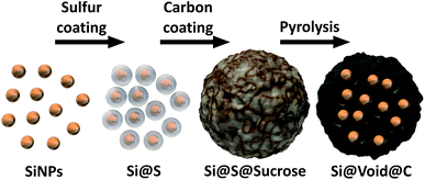 | ||
| Fig. 1 Schematic illustration of the synthesis process of the nanostructured silicon–carbon composite (Si@void@C). | ||
Transmission electron microscopy (TEM) evidences the void structure formation (Fig. 2). A uniform sulfur coating (5–20 nm thick) of the SiNPs (50–150 nm diameter) (Fig. 2a) protecting the SiNPs from decomposition during the alkaline treatment of the sucrose polymerization is obtained. Without the sulfur layer, the SiNPs are not stable during the synthesis in alkaline medium (Fig. S1†).
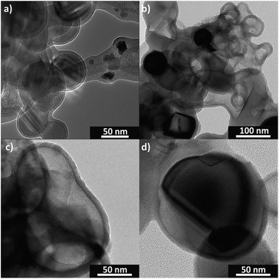 | ||
| Fig. 2 TEM images of the sulfur coated SiNPs (Si@S) (a) and the resulting silicon–carbon void structure (Si@void@C) (b–d). | ||
The resulting void structure contains voids with a diameter about 50–150 nm with a nearly 10 nm thick carbon shell (Fig. 2b–d). Obviously, the free volume does not completely compensate the lithiated silicon volume expansion of 300%. But introducing larger voids by a thicker sulfur shell led to poor electrical contact of the silicon cores (Fig. S2†). This phenomenon was also shown by other groups.45,46 However, due to the tailored voids the carbon matrix gains enough flexibility to compensate the volume change of the silicon.
The TEM images in Fig. 2 as well as the SEM images in Fig. 3 show that commercially available SiNPs (Fig. 3a and b) are partially aggregated – a typical phenomenon observed for nanoparticles in order to minimize the surface energy.
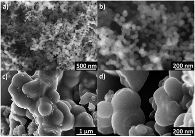 | ||
| Fig. 3 SEM images of the as-received SiNPs (a and b) and of the Si–C composite (Si@void@C) (c and d). | ||
This affects the morphology of the Si–C composite (Fig. 3c and d): mostly, particle aggregates are coated instead of individual particles. Nevertheless, with the resulting carbon coating, the silicon particles seem to be covered completely. The coated primary silicon particles are approximately 100–200 nm in diameter and form micrometer-sized agglomerates that decrease the surface area and the tap density of the composite.58 X-ray powder diffraction (PXRD) and Raman spectroscopy results as shown in Fig. 4 confirm the stability and intactness of crystalline SiNPs throughout the synthesis process. PXRD of the SiNPs and the Si–C composite (Fig. 4a) shows the typical diffraction pattern of cubic silicon.48 No diffraction peaks corresponding to graphitic carbon or silica could be observed in the PXRD pattern.
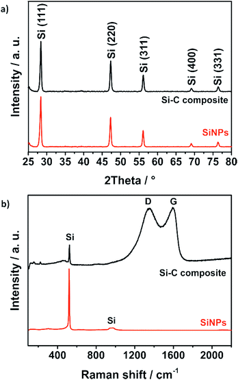 | ||
| Fig. 4 PXRD pattern (a) and Raman spectra (b) of bare SiNPs and the Si–C composite confirm the stability of the crystalline silicon nanoparticles during the synthesis. | ||
However, the emergence of amorphous silica phases during the alkaline treatment cannot be excluded. For this reason, Raman studies were carried out as well to reveal the absence of a characteristic band of the amorphous silica around 460 cm−1.59 The Raman spectrum of the Si–C composite shown in Fig. 4b exhibits a strong peak at 520 cm−1 corresponding to the characteristic peak of pure SiNPs. Another characteristic but weaker peak at 974 cm−1 of silicon is not visible.60 The two broad peaks of the Si–C composite at about 1350 cm−1 and 1600 cm−1 could be explained by the disordered D band and the graphitic G band of the carbon matrix. By fitting the spectra with a Lorentzian function to calculate the intensities of the D band and the G band, the degree of graphitization ID/IG ∼ 1 is calculated.61 That means that the carbon shell of the Si–C composite has a short-range-ordered carbon structure that matches well with the TEM investigations where clear carbon fringes are hardly observable. The silicon content of the Si–C composite which is around 30% was determined via an adapted stepwise combustion of the carbon matrix and oxidation of the silicon under air at 1000 °C (Fig. S3†).
The removal of the sulfur template during the pyrolysis is investigated and monitored by thermal gravimetric mass spectrometry (TGA-MS) displayed in Fig. 5. Firstly, the composite is heated under argon flow at 10 K min−1 to 850 °C and annealed for 2 h. The highest mass loss is at around 300 °C which is related to the carbonization of the polymerized sucrose and the removal of sulfur (Fig. 5a). According to the mass spectra of the evolved gas species (Fig. 5b), sulfur is decomposed presumably to hydrogen sulfide (HS, H2S), sulfur monoxide (SO, SO2) and disulphur (S2) matching the respective molar masses. The sulfur template could be removed almost completely and just around 8% sulfur remains in the Si–C composite, which was determined by CHNS elemental analysis.
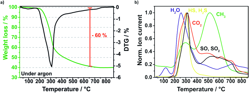 | ||
| Fig. 5 TGA profile of the pyrolysis (under argon) of the Si@S@sucrose compound (a) and the evolved gases detected by mass spectrometry (b). | ||
2.2 Electrochemical characterization
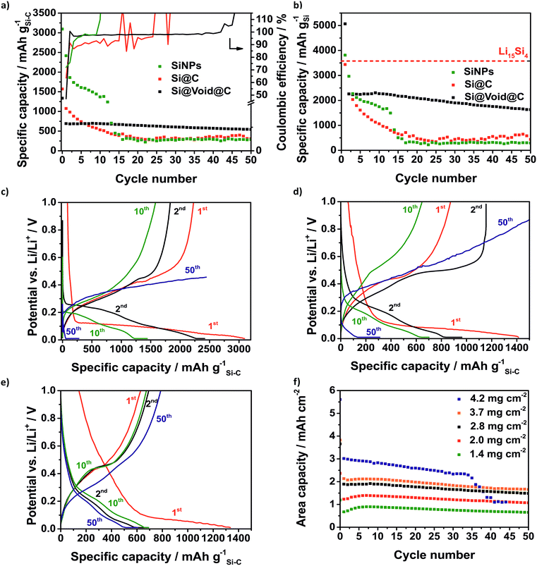
In the first cycle, the electrode with pure SiNPs shows the highest capacity of 3094 mA h g−1 based on the electrode mass because of the highest silicon content of 80% (Fig. 6a). The Si@C electrode contains 42% silicon and the Si@void@C electrode contains 23% silicon resulting in initial capacities of 1570 mA h g−1 and 1335 mA h g−1. During the first cycle all three silicon electrodes show a high irreversible capacity corresponding to an initial coulombic efficiency lower than 100%. On one side, there is a loss of electrically contacted active material because silicon is strained by the large mechanical stress during the initial lithiation of the crystalline SiNPs. On the other hand, the electrolyte is reductively decomposed at the anode surface where the solid decomposition products form a SEI which ideally inhibits further electrolyte reduction. The Si@void@C electrode has the lowest CE of 47% followed by the Si@C electrode with 64% and the SiNP electrode with 72%. Since sucrose is used as carbon source, the Si–C composites consist of a porous unordered carbon coating with dangling bonds. This leads to an increased surface of the composite which reacts with the electrolyte. Besides the SEI formation on the carbon surface, there is also a partially irreversible lithium intercalation in the carbon matrix leading to the higher initial loss of lithium. According to Chen et al. the CE of the Si@void@C electrode is lower than that of the Si@C electrode given that the surface area is increased by the higher void volume.53 In accordance to other publications, the CE of the Si–C anodes is much better in carbonate based electrolyte like LP30 (1 M LiPF6 in 1![[thin space (1/6-em)]](https://www.rsc.org/images/entities/char_2009.gif) :
:![[thin space (1/6-em)]](https://www.rsc.org/images/entities/char_2009.gif) 1 (m/m) ethylene carbonate/dimethyl carbonate) which is standardly used in lithium-ion batteries (Fig. S5†).14 But these groups of electrolytes could to be used in the lithium–sulfur chemistry because polysulfides react with carbonates.62 In this way a commonly used lithium–sulfur battery electrolyte containing 1 M bis(trifluoromethane)sulfonamide lithium salt (LiTFSI) and 0.25 M LiNO3 in 1
1 (m/m) ethylene carbonate/dimethyl carbonate) which is standardly used in lithium-ion batteries (Fig. S5†).14 But these groups of electrolytes could to be used in the lithium–sulfur chemistry because polysulfides react with carbonates.62 In this way a commonly used lithium–sulfur battery electrolyte containing 1 M bis(trifluoromethane)sulfonamide lithium salt (LiTFSI) and 0.25 M LiNO3 in 1![[thin space (1/6-em)]](https://www.rsc.org/images/entities/char_2009.gif) :
:![[thin space (1/6-em)]](https://www.rsc.org/images/entities/char_2009.gif) 1 (v/v) 1,2-dimethoxyethane (DME) and 1,3-dioxolane (DOL) is used. Lithium nitrate is beneficial for Li–S cells as it forms LixSOy-based SEIs on the anode side suppressing the polysulfide shuttle.63
1 (v/v) 1,2-dimethoxyethane (DME) and 1,3-dioxolane (DOL) is used. Lithium nitrate is beneficial for Li–S cells as it forms LixSOy-based SEIs on the anode side suppressing the polysulfide shuttle.63
Certainly, the low initial CE is a characteristic signature of many silicon anodes which has to be solved regarding the use of silicon anodes in lithium-ion batteries where the loss of lithium ions is crucial.62 In the case of Li–S batteries it is less critical because a prelithiated silicon anode with an already formed SEI is used. As expected, the SiNP electrode suffers from fast degradation as a result of the large volume change of the silicon whereby the SiNPs lose their electrical contact (Fig. 6a). Within 15 cycles the capacity declines to 387 mA h g−1 and the silicon can no longer be lithiated. After 9 cycles the CE rises to over 100% which could be related to the end of the reversible lithiation/delithiation. In the same way, the Si@C electrode shows a rapid capacity fading and a CE around 90% right from the start. Similar to the SiNP electrode the silicon cannot be reversibly lithiated after 15 cycles and the CE increases above 100%. The Si@void@C electrode achieves a relatively high lithiation capacity of 692 mA h g−1 after 10 cycles and high capacity retention for more than 50 cycles. Since the carbon shell is not cracked by the volume change, the SEI is stabilized at the carbon surface, and the CE is increased to around 98% in a few cycles and remained at this value there for more than 40 cycles. It also enables a good rate capability (Fig. S6a†).
In Fig. 6b the capacity calculated based on the silicon fraction is compared to the theoretical capacity of Li15Si4 (3579 mA h gSi−1). Due to the SEI formation and other lithium consuming side reactions, the capacity calculated based on the silicon mass of the SiNPs and the Si@void@C electrode is higher than the theoretical capacity of Li15Si4 in the first cycle.63 The Si@void@C electrode shows a capacity of 2255 mA h gSi−1 in the second cycle which corresponds to a utilization of silicon of 63%. After 15 cycles still 61% of the silicon in the Si@void@C could be lithiated, whereas the silicon in the SiNP electrode and the Si@C electrode could not be used.
As can be seen from the voltage profiles the first lithiation of the silicon consists of two parts (Fig. 6c–e): the potential decreases slowly to 0.1 V corresponding to the SEI formation and the Li intercalation in the carbon matrix. At a potential of ca. 0.1 V there is a plateau related to the lithiation of crystalline silicon to amorphous Li15Si4.64 The delithiation of the unstable Li15Si4 correlates with the charge plateau around 0.45 V.65 After the first cycle the silicon becomes amorphous and thus, there is no flat plateau during the discharge process in the following cycles.64 Due to the degradation of the SiNPs and the Si@C electrode, the charge plateau around 0.45 V is not visible in the 10th and in the 50th cycle and finally a charge cut-off voltage of 1 V could not be reached.
Regarding the potential use of the Si@void@C in commercial lithium–sulfur or lithium-ion cells the areal capacity is one crucial parameter.25 Many publications show Si–C electrodes with high cycle stability but low electrode loading causing a poor area related capacity.50,58,66Fig. 6f reveals the dependency of the electrode loading and the electrode stability. Typically, with an increasing electrode thickness the influence of the volume change of the silicon rises and the electrode degrades faster. Additionally, with higher loading, lithium diffusion to the active anode material is hampered leading to decreased silicon utilization as well.
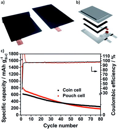
Due to the void structure high areal capacities above 2.5 mA h cm−2 could be achieved with only a slight capacity fading. Another requirement for the transfer to applicable cells is the potentially simple scalability of the Si@void@C composite synthesis. Thus, we were able to increase the batch size from a laboratory scale (2 g batch) to 50 g with a reproducible electrochemical performance which is shown in Fig. S6b.† From the developed Si–C electrode with at least an area DIN 4A in size, double-sided pouch electrodes (4.6 × 7.1 cm2) were cut out using laser-cutting (Fig. 7a). The anode and the cathode were welded on a nickel tap and assembled to a one-layered pouch cell (Fig. 7b).
As can be seen in Fig. 6f the electrochemical performance of the Si@void@C composite with a decreased electrode loading of 0.3 mg cm−2vs. Li/Li+ in pouch cells is comparable to the half cell testing in coin cells. In the second cycles 789 mA h g−1 could be reached in the pouch cell and 619 mA h g−1 in the coin cell. As explained above, the CE in the first cycle is only 38% in the coin cell and 50% in the pouch cell. In the second cycle the CE of the pouch cell rises above 100%. This could be related to wetting conditions through the irregular pressure distribution in single-layered pouch cells. However, in the following cycles a very stable CE around 97% in the coin cell and 96% in the pouch cell could be achieved for more than 80 cycles.
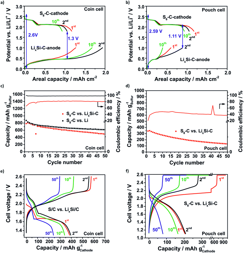
Generally, for the full cell concept it is reasonable to overbalance the anode for two reasons: firstly, the compensation of lithium losses through SEI formation and pulverization of the LixSi–C anode is one issue. Secondly, it is beneficial when the cathode (lithiation) discharge slope meets the delithiation slope of the anode at a constant potential in order to create a stable difference between the two potentials. The lower the difference between the lithiation slope of the cathode and delithiation slope of the anode, the lower the voltage value where the full cells need to be discharged being detrimental in terms of the electrolyte depletion. According to this the SLS cell on the coin cell level (Fig. 8a) is limited to the anode with a balancing of the practical areal capacities (2nd cycle) of the anode![[thin space (1/6-em)]](https://www.rsc.org/images/entities/char_2009.gif) :
:![[thin space (1/6-em)]](https://www.rsc.org/images/entities/char_2009.gif) cathode of 5
cathode of 5![[thin space (1/6-em)]](https://www.rsc.org/images/entities/char_2009.gif) :
:![[thin space (1/6-em)]](https://www.rsc.org/images/entities/char_2009.gif) 3. Unfortunately, the LixSi–C pouch anode needs to have a lower loading due to delamination effects during prelithiation at higher loadings. Thus, the SLS pouch cell (Fig. 8b) is limited to the S8–C cathode with a balancing anode
3. Unfortunately, the LixSi–C pouch anode needs to have a lower loading due to delamination effects during prelithiation at higher loadings. Thus, the SLS pouch cell (Fig. 8b) is limited to the S8–C cathode with a balancing anode![[thin space (1/6-em)]](https://www.rsc.org/images/entities/char_2009.gif) :
:![[thin space (1/6-em)]](https://www.rsc.org/images/entities/char_2009.gif) cathode of 10
cathode of 10![[thin space (1/6-em)]](https://www.rsc.org/images/entities/char_2009.gif) :
:![[thin space (1/6-em)]](https://www.rsc.org/images/entities/char_2009.gif) 11 and the discharge cut-off voltage has to be decreased to 1.11 V to delithiate the LixSi–C anode at least. Fig. 8c–f show the specific capacity retention and the corresponding voltage profiles of the SLS cells compared to the Li–S cell. Even though the SLS coin cell has a much lower lithium excess of only 76% than the Li–S cell with a huge lithium excess of about 2000% the capacity retention obtained for both concepts is comparable. In the beginning (2nd cycle) the capacity of the SLS cell is 807 mA h gsulfur−1 and of the Li–S cell is 830 mA h gsulfur−1 and after 50 cycles even 492 mA h gsulfur−1 in the SLS cell and 617 mA h gsulfur−1 in the Li–S cell are reached (Fig. 8c). The CE of the SLS cell is just around 80% because the used electrolyte is optimized for Li–S cells and is not suited for silicon anodes.8,14 Probably, the LiNO3 is consumed in the first cycle and the SEI could not be stabilized.67 In this way the electrolyte is decomposed repeatedly and the polysulfide shuttle is promoted.
11 and the discharge cut-off voltage has to be decreased to 1.11 V to delithiate the LixSi–C anode at least. Fig. 8c–f show the specific capacity retention and the corresponding voltage profiles of the SLS cells compared to the Li–S cell. Even though the SLS coin cell has a much lower lithium excess of only 76% than the Li–S cell with a huge lithium excess of about 2000% the capacity retention obtained for both concepts is comparable. In the beginning (2nd cycle) the capacity of the SLS cell is 807 mA h gsulfur−1 and of the Li–S cell is 830 mA h gsulfur−1 and after 50 cycles even 492 mA h gsulfur−1 in the SLS cell and 617 mA h gsulfur−1 in the Li–S cell are reached (Fig. 8c). The CE of the SLS cell is just around 80% because the used electrolyte is optimized for Li–S cells and is not suited for silicon anodes.8,14 Probably, the LiNO3 is consumed in the first cycle and the SEI could not be stabilized.67 In this way the electrolyte is decomposed repeatedly and the polysulfide shuttle is promoted.
The voltage profiles in Fig. 8e of the SLS cell show both characteristic plateaus during the discharge process. In comparison to the Li–S cell (Fig. S7†) the voltage profiles are shifted to lower voltages and the average cell voltage decreases from 2.1 V in the Li–S cell to around 1.7 V in the SLS cell because of the higher potential of the lithiation of silicon.
As expected, the SLS pouch cell shows a lower capacity of 348 mA h gsulfur−1 corresponding to a low capacity of 363 mA h ganode−1 related to the anode in the beginning (2nd cycle) and the capacity slowly decreases to 80 mA h gsulfur−1 (138 mA h ganode−1) after 50 cycles (Fig. 8d). The main reason for this is the overbalanced S8–C cathode. Thus, the sulfur could not be utilized completely and lithium is lost steadily because of the anode degradation. The CE is just around 40–50% and hence, only half of the amount obtained in the coin cell setup, which could be explained by the increased side reactions due to the higher electrolyte amount in the pouch cell and the polysulfide shuttle which could not be suppressed. In line with the low sulfur utilization, the discharge profile (Fig. 8f) exhibits only one plateau at around 1.9 V.
Nevertheless, it was possible to show the feasibility of the SLS cell on the pouch level by elucidating the crucial issues that occur when cell concepts are supposed to be scaled up from the coin cell level which is a important step towards commercialization. It could be underlined that the balancing of the SLS cell needs to be limited to the cathode to compensate lithium losses and to utilize the sulfur cathode completely. The low CE of the SLS cells indicates that research on electrolytes which are suited for SLS cells is crucial to achieve higher capacity retention.19 Tailoring of nanostructured silicon composites is necessary but for multilayer pouch cells the realization of electrodes with high active material loadings is challenging.
3 Experimental
3.1 Synthesis of the silicon–carbon composite
In order to cover silicon nanoparticles with sulfur, 10 g SiNPs (Alfa Aesar, 98%, APS ≥ 50 nm) and 34.626 g sulfur (Sigma Aldrich, ≥ 99.5%) (Si![[thin space (1/6-em)]](https://www.rsc.org/images/entities/char_2009.gif) :
:![[thin space (1/6-em)]](https://www.rsc.org/images/entities/char_2009.gif) S 1
S 1![[thin space (1/6-em)]](https://www.rsc.org/images/entities/char_2009.gif) :
:![[thin space (1/6-em)]](https://www.rsc.org/images/entities/char_2009.gif) 3 molar ratio) were mixed with a mixer mill (MM400, Retsch) for 5 min at 25 Hz and heated for 30 min at 155 °C. The covered particles (Si@S) were ground with the mixer mill again and 40.220 g Si@S were suspended in a 178 ml mixture of ethanol/water (1
3 molar ratio) were mixed with a mixer mill (MM400, Retsch) for 5 min at 25 Hz and heated for 30 min at 155 °C. The covered particles (Si@S) were ground with the mixer mill again and 40.220 g Si@S were suspended in a 178 ml mixture of ethanol/water (1![[thin space (1/6-em)]](https://www.rsc.org/images/entities/char_2009.gif) :
:![[thin space (1/6-em)]](https://www.rsc.org/images/entities/char_2009.gif) 1 v/v). 51.884 g of sucrose (Sigma Aldrich, ≥ 99%) was added and after a 10 min ultra-sonic treatment, 3459 mg of a 2.5 M sodium hydroxide solution was added dropwise under vigorous stirring. The mixture was heated for 3 h at 100 °C and 6 h at 160 °C. To remove the sulfur and carbonize the polymerized sucrose the grinded Si@S@sucrose compound is heated under argon with 10 K min−1 to 850 °C annealed for 2 h.
1 v/v). 51.884 g of sucrose (Sigma Aldrich, ≥ 99%) was added and after a 10 min ultra-sonic treatment, 3459 mg of a 2.5 M sodium hydroxide solution was added dropwise under vigorous stirring. The mixture was heated for 3 h at 100 °C and 6 h at 160 °C. To remove the sulfur and carbonize the polymerized sucrose the grinded Si@S@sucrose compound is heated under argon with 10 K min−1 to 850 °C annealed for 2 h.
3.2 Structural characterization
The nanoscale structure and morphology of the Si–C composite were examined using a TEM JEM-2100 from JEOL (200 kV acceleration voltage) and SEM DSM 982 GEMINI from Zeiss (7 kV acceleration voltage) and SU8020 from Hitachi (5 kV acceleration voltage). PXRD experiments were performed with a Pro Panalytical X'pert diffractometer using Cu Kα1 radiation and a scan range 2Θ = 10–80°. Raman spectroscopy data were collected using a Renishaw inVia Raman spectrometer under ambient conditions using a laser with a wavelength of 514 nm. By determining the degree of graphitization ID/IG, the intensities of the D band and the G band were calculated by fitting the spectra with a Lorentzian function. A thermal analysis of the pyrolysis was performed using a Netzsch STA 409 PC Luxx simultaneous thermal analyzer combined with an Aëolos QMS 403C quadrupole mass spectrometer. Analogous to the synthesis procedure, the Si@S@sucrose compound was heated at 10 K min−1 to 850 °C for 2 h under argon flow. To quantify the silicon content, the Si–C composite was heated under argon at 10 K min−1 to 500 °C and held for 30 min and heated again at 5 K min−1 to 1000 °C and held for 30 min using a Netzsch STA 409 PC/PG simultaneous thermal analyzer. The carbon, hydrogen, nitrogen and sulfur contents of the Si@void@C composite were determined using an elemental CHNS analyzer vario MICRO form ELEMENTAR.3.3 Electrochemical characterization
![[thin space (1/6-em)]](https://www.rsc.org/images/entities/char_2009.gif) :
:![[thin space (1/6-em)]](https://www.rsc.org/images/entities/char_2009.gif) 1 (v/v) 1,2-dimethoxyethane (DME, Sigma Aldrich, 99.5% anhydrous) and 1,3-dioxolane (DOL, Sigma Aldrich, 99.8%, anhydrous). Additionally, a 25 μm thick porous polypropylene separator (Celgard 2500) and a stainless steel spacer (100 μm) were used. Single-layer pouch cells containing a Si–C cathode (4.6 × 7.1 cm2, 0.6 mg cm−2) and a lithium anode (4.6 × 7.1 cm2, 250 μm), a Celgard 2500 separator (5.0 × 7.5 cm2) and 2 ml electrolyte (1 M LiTFSI, 0.25 M LiNO3 in 1
1 (v/v) 1,2-dimethoxyethane (DME, Sigma Aldrich, 99.5% anhydrous) and 1,3-dioxolane (DOL, Sigma Aldrich, 99.8%, anhydrous). Additionally, a 25 μm thick porous polypropylene separator (Celgard 2500) and a stainless steel spacer (100 μm) were used. Single-layer pouch cells containing a Si–C cathode (4.6 × 7.1 cm2, 0.6 mg cm−2) and a lithium anode (4.6 × 7.1 cm2, 250 μm), a Celgard 2500 separator (5.0 × 7.5 cm2) and 2 ml electrolyte (1 M LiTFSI, 0.25 M LiNO3 in 1![[thin space (1/6-em)]](https://www.rsc.org/images/entities/char_2009.gif) :
:![[thin space (1/6-em)]](https://www.rsc.org/images/entities/char_2009.gif) 1 (v/v) DME/DOL) were stacked in a glove box, as well. The galvanostatic cycling was performed with a BaSyTec CTS cell test system between 10 mV and 1 V and at a current density of 0.1 mA cm−2 in the first cycle and 0.5 mA cm−2 in the following cycles. In terms of the Si@void@C electrode with a loading of 2.8 mg cm−2 the current density corresponds to a specific current of 36 mA g−1 (C/24) in the first cycle and to 179 mA g−1 (C/5) in the following cycles. The C-rate is based on the weight of silicon (3579 mA h gSi−1). During discharge a constant voltage step was applied. The Li–S cells were cycled between 1.8 V and 2.6 V with a C-rate of C/10. The capacities of the Li–S cells were calculated based on the weight of sulfur (1672 mA h g−1).
1 (v/v) DME/DOL) were stacked in a glove box, as well. The galvanostatic cycling was performed with a BaSyTec CTS cell test system between 10 mV and 1 V and at a current density of 0.1 mA cm−2 in the first cycle and 0.5 mA cm−2 in the following cycles. In terms of the Si@void@C electrode with a loading of 2.8 mg cm−2 the current density corresponds to a specific current of 36 mA g−1 (C/24) in the first cycle and to 179 mA g−1 (C/5) in the following cycles. The C-rate is based on the weight of silicon (3579 mA h gSi−1). During discharge a constant voltage step was applied. The Li–S cells were cycled between 1.8 V and 2.6 V with a C-rate of C/10. The capacities of the Li–S cells were calculated based on the weight of sulfur (1672 mA h g−1).
![[thin space (1/6-em)]](https://www.rsc.org/images/entities/char_2009.gif) :
:![[thin space (1/6-em)]](https://www.rsc.org/images/entities/char_2009.gif) 1 (v/v) DME/DOL). Accordingly, the single-layer SLS pouch cells consisting of a S8–C cathode, a Celgard 2500 separator and a LixSi–C anode and 2 ml electrolyte (1 M LiTFSI, 0.25 M LiNO3 in 1
1 (v/v) DME/DOL). Accordingly, the single-layer SLS pouch cells consisting of a S8–C cathode, a Celgard 2500 separator and a LixSi–C anode and 2 ml electrolyte (1 M LiTFSI, 0.25 M LiNO3 in 1![[thin space (1/6-em)]](https://www.rsc.org/images/entities/char_2009.gif) :
:![[thin space (1/6-em)]](https://www.rsc.org/images/entities/char_2009.gif) 1 (v/v) DME/DOL) were assembled. The galvanostatic cycling was performed with a BaSyTec CTS cell test system with a C-rate of C/10. The coin cell testing was performed between 1.3 and 2.6 V and the pouch cells were cycled in a smaller voltage range between 1.11 and 2.59 V. During charging a constant voltage step is applied to the SLS pouch cells.
1 (v/v) DME/DOL) were assembled. The galvanostatic cycling was performed with a BaSyTec CTS cell test system with a C-rate of C/10. The coin cell testing was performed between 1.3 and 2.6 V and the pouch cells were cycled in a smaller voltage range between 1.11 and 2.59 V. During charging a constant voltage step is applied to the SLS pouch cells.
4 Conclusions
In summary, we have synthesized nanostructured silicon–carbon composites via a simple, easily scalable route without hydrofluoric acid treatment. Sulfur was used as a low-cost intermediate template to create tailored voids between silicon cores and carbon shells via in situ removal in parallel to the carbon pyrolysis. Due to the void structure, the electrode degradation caused by the volume change of the silicon could be balanced. After 10 cycles, capacities as high as 2270 mA h gSi−1 (690 mA h g−1) were achieved and the cycle life could be enhanced compared to pure SiNPs and a Si@C electrode without voids. Due to the high areal capacity of 2 mA h cm2 the prelithiated Si–C anode was successfully combined with a sulfur cathode in a SLS full cell on coin cell and on pouch cell levels. Even with only a small lithium excess of 76% and a relatively low amount of electrolyte (12 μl mgsulfur−1) a high capacity of about 807 mA h gsulfur−1 (2nd cycle) could be achieved, a capacity comparable to that of standard Li–S cells which use a much higher lithium excess of up to 2000%.Conflicts of interest
There are no conflicts to declare.Acknowledgements
This research received funding from the European Union's Horizon 2020 research and innovation programme through the project ALISE (GA no. 666157).Notes and references
- P. Strubel, S. Thieme, T. Biemelt, A. Helmer, M. Oschatz, J. Brückner, H. Althues and S. Kaskel, Adv. Funct. Mater., 2015, 25(2), 287 CrossRef.
- J. Brückner, S. Thieme, H. T. Grossmann, S. Dörfler, H. Althues and S. Kaskel, J. Power Sources, 2014, 268, 82 CrossRef.
- M. Agostini, J. Hassoun, J. Liu, M. Jeong, H. Nara, T. Momma, T. Osaka, Y.-K. Sun and B. Scrosati, ACS Appl. Mater. Interfaces, 2014, 6(14), 10924 CrossRef PubMed.
- R. Cao, W. Xu, D. Lv, J. Xiao and J.-G. Zhang, Adv. Energy Mater., 2015, 5(16), 1402273 CrossRef.
- J. Brückner, S. Thieme, F. Böttger-Hiller, I. Bauer, H. T. Grossmann, P. Strubel, H. Althues, S. Spange and S. Kaskel, Adv. Funct. Mater., 2014, 24(9), 1284 CrossRef.
- X. Pu, G. Yang and C. Yu, Nano Energy, 2014, 9, 318 CrossRef.
- J. K. Lee, C. Oh, N. Kim, J.-Y. Hwang and Y.-K. Sun, J. Mater. Chem. A, 2016 Search PubMed.
- M. Piwko, T. Kuntze, S. Winkler, S. Straach, P. Härtel, H. Althues and S. Kaskel, J. Power Sources, 2017, 351, 183 CrossRef.
- H. Wu and Y. Cui, Nano Today, 2012, 7(5), 414 CrossRef.
- M. Ling, H. Zhao, X. Xiaoc, F. Shi, M. Wu, J. Qiu, S. Li, X. Song, G. Liu and S. Zhang, J. Mater. Chem. A, 2015, 3(5), 2036 RSC.
- X. H. Liu, L. Zhong, S. Huang, S. X. Mao, T. Zhu and J. Y. Huang, ACS Nano, 2012, 6(2), 1522 CrossRef PubMed.
- H. Kim, M. Seo, M.-H. Park and J. Cho, Angew. Chem., Int. Ed., 2010, 49(12), 2146 CrossRef PubMed.
- J. Xu, Q. Zhang and Y.-T. Cheng, J. Electrochem. Soc., 2015, 163(3), A401–A405 CrossRef.
- M. Weinberger and M. Wohlfahrt-Mehrens, Electrochim. Acta, 2016, 191, 124 CrossRef.
- T. Takahashi, M. Yamagata and M. Ishikawa, Prog. Nat. Sci.: Mater. Int., 2015, 25(6), 612 CrossRef.
- H. Jha, I. Buchberger, X. Cui, S. Meini and H. A. Gasteiger, J. Electrochem. Soc., 2015, 162(9), A1829–A1835 CrossRef.
- R. Elazari, G. Salitra, G. Gershinsky, A. Garsuch, A. Panchenko and D. Aurbach, Electrochem. Commun., 2012, 14(1), 21 CrossRef.
- D. A. Dalla Corte, A. C. Gouget-Laemmel, K. Lahlil, G. Caillon, C. Jordy, J.-N. Chazalviel, T. Gacoin, M. Rosso and F. Ozanam, Electrochim. Acta, 2016, 201, 70 CrossRef.
- M. Piwko, S. Thieme, C. Weller, H. Althues and S. Kaskel, J. Power Sources, 2017, 362, 349 CrossRef.
- J. Ha and U. Paik, J. Power Sources, 2013, 244, 463 CrossRef.
- Y. Zhao, L. Peng, Y. Ding and G. Yu, Chem. Commun., 2014, 50(85), 12959 RSC.
- B. Hertzberg, A. Alexeev and G. Yushin, J. Am. Chem. Soc., 2010, 132(25), 8548 CrossRef PubMed.
- C. K. Chan, R. Ruffo, S. S. Hong, R. A. Huggins and Y. Cui, J. Power Sources, 2009, 189(1), 34 CrossRef.
- V. Chakrapani, F. Rusli, M. A. Filler and P. A. Kohl, J. Power Sources, 2012, 205, 433 CrossRef.
- A. Krause, S. Dorfler, M. Piwko, F. M. Wisser, T. Jaumann, E. Ahrens, L. Giebeler, H. Althues, S. Schadlich, J. Grothe, A. Jeffery, M. Grube, J. Bruckner, J. Martin, J. Eckert, S. Kaskel, T. Mikolajick and W. M. Weber, Sci. Rep., 2016, 6, 27982 CrossRef PubMed.
- Y. Yang, M. T. McDowell, A. Jackson, J. J. Cha, S. S. Hong and Y. Cui, Nano Lett., 2010, 10(4), 1486 CrossRef PubMed.
- M. Hagen, E. Quiroga-González, S. Dörfler, G. Fahrer, J. Tübke, M. J. Hoffmann, H. Althues, R. Speck, M. Krampfert, S. Kaskel and H. Föll, J. Power Sources, 2014, 248, 1058 CrossRef.
- Y.-Y. Kim, J.-H. Lee and H.-J. Kim, Phys. E, 2017, 85, 223 CrossRef.
- G. Hwang, H. Park, T. Bok, S. Choi, S. Lee, I. Hwang, N.-S. Choi, K. Seo and S. Park, Chem. Commun., 2015, 51(21), 4429 RSC.
- Y.-X. Yin, S. Xin, L.-J. Wan, C.-J. Li and Y.-G. Guo, J. Phys. Chem. C, 2011, 115(29), 14148 CrossRef.
- S.-K. Lee, S.-M. Oh, E. Park, B. Scrosati, J. Hassoun, M.-S. Park, Y.-J. Kim, H. Kim, I. Belharouak and Y.-K. Sun, Nano Lett., 2015, 15(5), 2863 CrossRef PubMed.
- C. Shen, M. Ge, A. Zhang, X. Fang, Y. Liu, J. Rong and C. Zhou, Nano Energy, 2016, 19, 68 CrossRef.
- L. Liu, J. Lyu, T. Li and T. Zhao, Nanoscale, 2016, 8(2), 701 RSC.
- Y. Yan, Y.-X. Yin, S. Xin, J. Su, Y.-G. Guo and L.-J. Wan, Electrochim. Acta, 2013, 91, 58 CrossRef.
- J. Sourice, A. Bordes, A. Boulineau, J. P. Alper, S. Franger, A. Quinsac, A. Habert, Y. Leconte, E. de Vito, W. Porcher, C. Reynaud, N. Herlin-Boime and C. Haon, J. Power Sources, 2016, 328, 527 CrossRef.
- L. Zhang, Y. Wang, G. Kan, Z. Zhang, C. Wang, Z. Zhong and F. Su, RSC Adv., 2014, 4(81), 43114 RSC.
- R. C. de Guzman, J. Yang, M. M.-C. Cheng, S. O. Salley and K. Y. Simon Ng, J. Power Sources, 2014, 246, 335 CrossRef.
- J. Hassoun, J. Kim, D.-J. Lee, H.-G. Jung, S.-M. Lee, Y.-K. Sun and B. Scrosati, J. Power Sources, 2012, 202, 308 CrossRef.
- H. S. Kim, T.-G. Jeong and Y.-T. Kim, J. Electrochem. Sci. Technol., 2016, 7(3), 228 CrossRef.
- B. Li, S. Li, J. Xu and S. Yang, Energy Environ. Sci., 2016, 9(6), 2025 RSC.
- D. Zhou, M. Liu, Q. Yun, X. Wang, Y.-B. He, B. Li, Q.-H. Yang, Q. Cai and F. Kang, Small, 2017, 13(3), 1602015 CrossRef PubMed.
- Z. Lu, N. Liu, H.-W. Lee, J. Zhao, W. Li, Y. Li and Y. Cui, ACS Nano, 2015, 9(3), 2540 CrossRef PubMed.
- N. Liu, H. Wu, M. T. McDowell, Y. Yao, C. Wang and Y. Cui, Nano Lett., 2012, 12(6), 3315 CrossRef PubMed.
- H. Wu, G. Zheng, N. Liu, T. J. Carney, Y. Yang and Y. Cui, Nano Lett., 2012, 12(2), 904 CrossRef PubMed.
- S. Chen, M. L. Gordin, R. Yi, G. Howlett, H. Sohn and D. Wang, Phys. Chem. Chem. Phys., 2012, 14(37), 12741 RSC.
- S. Iwamura, H. Nishihara and T. Kyotani, J. Phys. Chem. C, 2012, 116(10), 6004 CrossRef.
- X. Li, P. Meduri, X. Chen, W. Qi, M. H. Engelhard, W. Xu, F. Ding, J. Xiao, W. Wang, C. Wang, J.-G. Zhang and J. Liu, J. Mater. Chem., 2012, 22(22), 11014 RSC.
- X.-y. Zhou, J.-j. Tang, J. Yang, J. Xie and L.-l. Ma, Electrochim. Acta, 2012, 87, 663 CrossRef.
- L. Pan, H. Wang, D. Gao, S. Chen, L. Tan and L. Li, Chem. Commun., 2014, 50(44), 5878 RSC.
- Y. Ru, D. G. Evans, H. Zhu and W. Yang, RSC Adv., 2014, 4(1), 71 RSC.
- H. Tao, L.-Z. Fan, W.-L. Song, M. Wu, X. He and X. Qu, Nanoscale, 2014, 6(6), 3138 RSC.
- C. Pang, H. Song, N. Li and C. Wang, RSC Adv., 2015, 5(9), 6782 RSC.
- X. Xiao, W. Zhou, Y. Kim, I. Ryu, M. Gu, C. Wang, G. Liu, Z. Liu and H. Gao, Adv. Funct. Mater., 2015, 25(9), 1426 CrossRef.
- L. Y. Yang, H. Z. Li, J. Liu, Z. Q. Sun, S. S. Tang and M. Lei, Sci. Rep., 2015, 5, 10908 CrossRef PubMed.
- T. Jaumann, M. Herklotz, M. Klose, K. Pinkert, S. Oswald, J. Eckert and L. Giebeler, Chem. Mater., 2015, 27(1), 37 CrossRef.
- L. Su, J. Xie, Y. Xu, L. Wang, Y. Wang and M. Ren, Phys. Chem. Chem. Phys., 2015, 17(27), 17562 RSC.
- K. McCormac, I. Byrd, R. Brannen, B. Seymour, J. Li and J. Wu, Phys. Status Solidi, 2015, 212(4), 877 CrossRef.
- N. Liu, Z. Lu, J. Zhao, M. T. McDowell, H.-W. Lee, W. Zhao and Y. Cui, Nat. Nanotechnol., 2014, 9(3), 187 CrossRef PubMed.
- A. Perriot, D. Vandembroucq, E. Barthel, V. Martinez, L. Grosvalet, C. Martinet and B. Champagnon, J. Am. Ceram. Soc., 2006, 89(2), 596 CrossRef.
- J. Lin, J. He, Y. Chen, Q. Li, B. Yu, C. Xu and W. Zhang, Electrochim. Acta, 2016, 215, 667 CrossRef.
- Y. Zhou, S. L. Candelaria, Q. Liu, E. Uchaker and G. Cao, Nano Energy, 2015, 12, 567 CrossRef.
- M. Ko, S. Chae and J. Cho, ChemElectroChem, 2015, 2(11), 1645 CrossRef PubMed.
- A. Tokranov, R. Kumar, C. Li, S. Minne, X. Xiao and B. W. Sheldon, Adv. Energy Mater., 2016, 6(8), 1502302 CrossRef.
- M. Ashuri, Q. He and L. L. Shaw, Nanoscale, 2016, 8(1), 74 RSC.
- M. N. Obrovac and V. L. Chevrier, Chem. Rev., 2014, 114(23), 11444 CrossRef PubMed.
- Z. Sun, S. Tao, X. Song, P. Zhang and L. Gao, J. Electrochem. Soc., 2015, 162(8), A1530–A1536 CrossRef.
- T. Yim, M.-S. Park, J.-S. Yu, K. J. Kim, K. Y. Im, J.-H. Kim, G. Jeong, Y. N. Jo, S.-G. Woo, K. S. Kang, I. Lee and Y.-J. Kim, Electrochim. Acta, 2013, 107, 454 CrossRef.
Footnote |
| † Electronic supplementary information (ESI) available. See DOI: 10.1039/c8ta03647k |
| This journal is © The Royal Society of Chemistry 2018 |

