DOI:
10.1039/C8TA02695E
(Review Article)
J. Mater. Chem. A, 2018,
6, 12185-12214
Layered tin sulfide and selenide anode materials for Li- and Na-ion batteries†
Received
23rd March 2018
, Accepted 22nd May 2018
First published on 28th May 2018
Abstract
Layered tin sulfides have attracted great interest as high-capacity anode materials in Li-ion batteries (LIBs) and Na-ion batteries (NIBs). In this review, we focus on the recent research progress in the area of design and synthesis of tin sulfide and selenide (SnS, SnS2, SnSe, and SnSe2) based anode materials for LIBs and NIBs. After a brief introduction of the energy concerns and the development prospects of LIBs and NIBs, we further detailed the properties and advantages of tin sulfide and selenide based anode materials for LIBs and NIBs. Besides the material structure design and optimization, the underlying mechanism and theoretical analysis for improved electrochemical performance are also presented. Additionally, comparison of tin sulfides and selenides is also provided. Innovative strategies that have demonstrated the effectiveness of enhancing the performance of tin sulfide and selenide based anode materials for LIBs and NIBs are summarized. We hope that this timely review can shed light on the research and development of tin sulfides and selenides as high-performance anode materials which are not only a good supplement to the material pool of commercialized LIBs, but also help facilitate the development of low-cost and sustainable NIBs for stationary energy storage in the future.
1. Introduction
With the increasing demand for green energy, highly efficient energy storage devices have drawn significant attention.1–6 Li-ion batteries (LIBs) and Na-ion batteries (NIBs) are two of the most important types of energy storage systems that have been investigated extensively owing to their advantages of environmental friendliness, high energy/power density and long cycle life.7–14 LIBs have already made great commercial success in portable electronics, and recently application of LIBs as power sources for electric vehicles (EVs) and hybrid electric vehicles (HEVs) has raised intense attention in many countries, especially in China.15,16 Nevertheless, owing to the limited reserves of Li resources, NIBs which share a similar operation mechanism to LIBs have recently re-gained great interest as a promising alternative to LIBs17–23 because of the rich abundance of Na in earth.
To achieve high energy density for LIBs and NIBs, it is crucial to develop high-capacity electrode materials, especially anode materials.24–27 Two-dimensional (2D) materials, i.e., layered transition-metal chalcogenides (TMCs), graphene, etc., represent a class of novel materials that possess unique properties due to the reduced dimension.28–39 Layered metal sulfides are considered as promising anode materials for LIBs and NIBs due to relatively weaker M–X (X = S, Se) ionic bonds which endow the material with kinetically favorable performances.19,40–48 In particular, layered tin sulfides and selenides (SnS, SnS2, SnSe, and SnSe2) with tunable spacing structures have attracted intensive attention as promising anode materials for LIBs and NIBs owing to their high theoretical capacity and high electrical conductivity and earth abundance of sulfur, selenium and tin (Table 1).29,42,49,50 Until now, a tremendous number of papers have been published in a short period on applications of SnS, SnS2, SnSe, and SnSe2 (Tables S1–S6, ESI†). Although some of the research on SnS, SnS2, SnSe, and SnSe2 anode materials for LIBs and NIBs have been mentioned in previous reviews,41,45,48,51–55 there is still no systematic review on this topic. Therefore, it is of high importance to summarize the recent development of tin sulfide and selenide based anode materials for LIBs and NIBs to provide the direction of future research in this field. This review serves this purpose. In this review, we present the key research breakthrough on tin sulfide and selenide based anode materials for LIBs and NIBs including the underlying design concept, material synthesis methods and electrochemical reaction mechanisms associated with the electrode material. Additionally, the emerging challenges and some perspectives on the development of tin sulfide and selenide based anode materials for LIBs and NIBs are also summarized.
Table 1 Physical and electrical properties of layered SnS, SnS2, SnSe, and SnSe2 for LIBs and NIBs51,56–59
| Compound/structure phasea (typical color and density/g cm−3) |
Interlayer spacingb [Å] |
Battery type |
Electrochemical reactionc (eqn (1): conversion reaction, usually irreversible; eqn (2): alloying reaction, reversible) |
Theoretical capacity (reversible)d [mA h g−1] |
Average discharge potential vs. Li+/Li or Na+/Na [V] |
Volume expansiong [%] |
Electrical conductivity at 300 K [S cm−1]h |
|
Website: https://www.webelements.com.
The effective ionic radii of Li is 0.76 Å and Na is 1.02 Å.
Intercalation eqn (0) is not shown here, although it may be vital in a capacitance-dominated system.
The theoretical reversible capacities based on alloying reaction.19,41,68
If based on the formation of Na2S2, the theoretical capacity of SnS2 as a NIB anode material will be 843 mA h g−1.69
Based on the formation of Li4.25Sn and Li2Se.
Some data may differ based on alternative methods.70
Reported electron transport properties may vary depending on different literature sources.56
|
| SnS/orthorhombic, herzenbergite (brown-black/grey) (5.08) |
4.33 |
LIBs |
SnS + 2Li+ + 2e− ↔ Sn + Li2S |
(1) |
1137 (782) |
1.411 |
197 |
3.3 × 10⁻² |
| Sn + 4.4Li+ + 4.4e− ↔ Li4.4Sn |
(2) |
| NIBs |
SnS + 2Na+ + 2e− ↔ Sn + Na2S |
(1) |
1022 (667) |
1.287 |
343 (242) |
| Sn + 3.75Na+ + 3.75e− ↔ Na3.75Sn |
(2) |
| SnS2/hexagonal, berndtite (yellow) (4.50) |
5.90 |
LIBs |
SnS2 + 4Li+ + 4e− ↔ Sn + 2Li2S |
(1) |
1231 (645) |
1.584 |
179 |
1 × 10⁻³ |
| Sn + 4.4Li+ + 4.4e− ↔ Li4.4Sn |
(2) |
| NIBs |
SnS2 + 4Na+ + 4e− ↔ Sn + 2Na2S |
(1) |
1136 (584)e |
1.461 |
315 (324) |
| Sn + 3.75Na+ + 3.75e− ↔ Na3.75Sn |
(2) |
| SnSe/orthorhombic (grey) (6.18) |
4.44 (ref. 60) |
LIBs |
SnSe + 2Li+ + 2e− ↔ Sn + Li2Se |
(1) |
847 (ref. 61)f (596)62 |
— |
— |
1 × 101 (ref. 63) |
| Sn + 4.4Li+ + 4.4e− ↔ Li4.4Sn |
(2) |
| NIBs |
SnSe + 2Na+ + 2e− ↔ Sn + Na2Se |
(1) |
780 (ref. 64 and 65) |
— |
— |
| Sn + 3.75Na+ + 3.75e− ↔ Na3.75Sn |
(2) |
| SnSe2/hexagonal (red-brown) (5.00) |
6.14 |
LIBs |
SnSe2 + 4Li+ + 4e− ↔ Sn + 2Li2Se |
(1) |
813 (ref. 62)/800 (ref. 61)f (426)66 |
— |
— |
1.7 × 100 (ref. 67) |
| Sn + 4.4Li+ + 4.4e− ↔ Li4.4Sn |
(2) |
| NIBs |
SnSe2 + 4Na+ + 4e− ↔ Sn + 2Na2Se |
(1) |
756 (ref. 59) |
— |
— |
| Sn + 3.75Na+ + 3.75e− ↔ Na3.75Sn |
(2) |
2. SnS
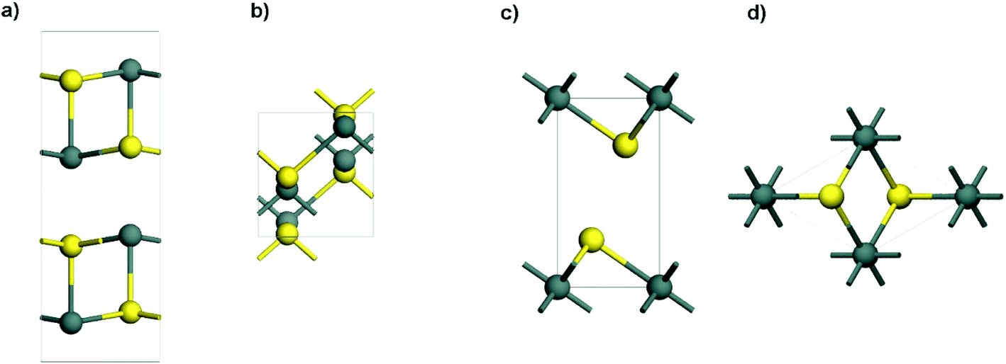
Tin sulfides have been well investigated for various applications because of their layered structures and peculiarities of ready availability for large scale production. Among them, two typical semi-conductive compounds with a single oxidation state are orthorhombic SnS (Fig. 1a and b) and hexagonal SnS2 (Fig. 1c and d), which are different from the Sn2S3 compound that has a structural distortion.56,71,72 As one of the attractive anode materials for LIBs and NIBs, SnS has high theoretical capacities (1137 mA h g−1 for LIBs and 1022 mA h g−1 for NIBs). The electrochemical reactions and alloying/dealloying mechanisms of SnS in LIBs and NIBs are shown in Table 1. However, the mechanism involving conversion reactions and the (de)alloying process could lead to kinetic problems in terms of reactivity, mass transport, and nucleation.73 Additionally, SnS has low electrical conductivity, and experiences a large volume expansion during repeated charge–discharge processes.74 All of this can cause severe structural degradation and further lead to capacity fading. To overcome these problems, much effort has been made to improve the performance of SnS anode materials for LIBs and NIBs, including the morphological control and doping of SnS,75–85 hybridization of SnS with conductive materials (e.g., polymer, carbon, graphene and 2D MXenes),86–92 and structural design of an integrated SnS hybrid electrode.42,93,94
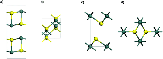 |
| | Fig. 1 Side view and top view of the layered structures of (a and b) orthorhombic SnS and (c and d) hexagonal SnS2 (atom color code: Sn, dark cyan; S, yellow). | |
2.1 SnS for Li-ion batteries
2.1.1 Structurally designed SnS as the anode.
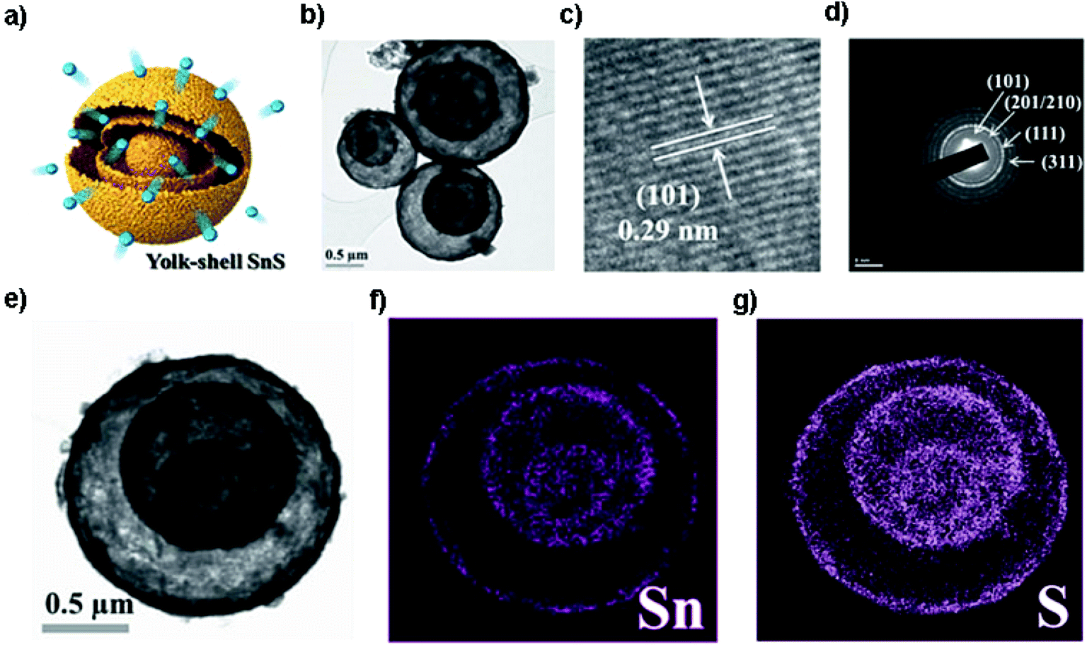
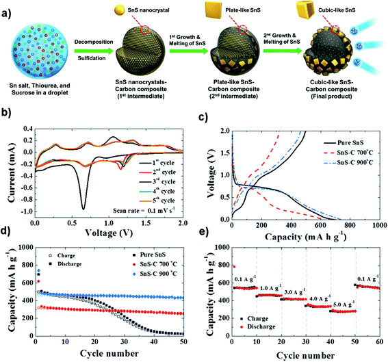
Pioneered by the Hayashi and Tu group,95,96 SnS has drawn increasing attention as a promising anode material for LIBs. The Tu group firstly reported that SnS nanoparticles synthesized by mechanical milling could deliver a discharge capacity of 400 mA h g−1 after 40 cycles. The poor cycling performance was attributed to the Li2S originating from the reaction of SnS and Li+ and the poor conductivity of SnS.96 Much effort has been made to improve the performance of SnS as an anode material for LIBs by the above-mentioned strategies. For example, in order to achieve a reduced Li-ion and electron diffusion distance, the functional coating may offer more active sites to host Li ions for higher capacity. As an example, SnS nanosheets coated with MoS2 ultrathin nanowalls and amorphous carbon via a facile hydrothermal process have been designed to prevent the direct exposure of SnS to the electrolyte and also maintain the electrode structural stability. The composite delivered a superior long-term capacity of 718 mA h g−1 after 700 cycles at 2 A g−1, and a high rate capability of 675 mA h g−1 at 5 A g−1.97 Moreover, designing a core–shell structure was also found to be one of the effective nanostructure engineering methods to improve the electrode cycling performance of SnS. Choi et al. designed yolk–shell SnS microspheres (Fig. 2a) with a distinctive double-shell crystalline SnS@void@SnS configuration via sulfidation of the SnO2/C precursor, as shown in Fig. 2b–g. The unique core–shell SnS electrode delivered an outstanding electrochemical performance with a discharge capacity of 672 mA h g−1 after 150 cycles at 1 A g−1 in the voltage range from 0.001 to 1.0 V and exhibited a high rate capability due to the unique structure.83 Very recently, Deng et al. prepared a coconut-like hollow SnS@C composite via a controlled sulfurization in a nanospace-confined way. This method could not only provide appropriate interior void space for accommodating the volume expansion but also shorten the electron/ion transfer path by a face-to-face contact mode. The core–shell SnS@C composite achieved an excellent reversible capacity of 936 mA h g−1 after 50 cycles at 0.1 A g−1 and 830 mA h g−1 after another 250 cycles at 0.5 A g−1 in the voltage range of 0.01–2.5 V as well as outstanding performance of the LiMn2O4//SnS@C full cell thereof.98 These strategies could solve the problems with regard to the low conductivity, reaction kinetics and serious structure pulverization/aggregation during the charge/discharge process. Nevertheless, energy density is one of the most important considerations for electrode design, so it should be considered and evaluated in designing core–shell structures for practical application in the future.
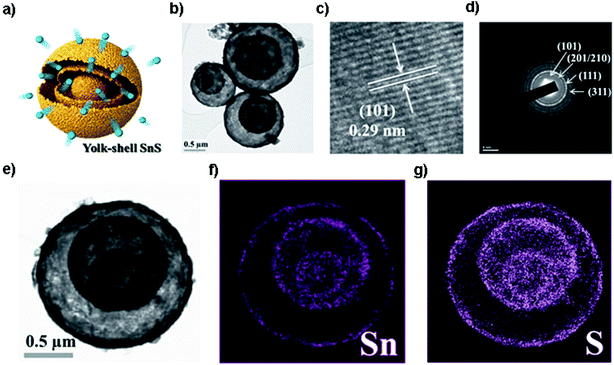 |
| | Fig. 2 (a) Schematic illustration and (b) TEM image of the yolk–shell-structured SnS microsphere with double shells and one core, and the related (c) HRTEM image, (d) SAED pattern and (e–g) dot-mapping images showing the polycrystalline phase-pure SnS and uniform distribution of Sn and S components. Reproduced with permission and modification.83 Copyright 2014, Wiley-VCH. | |
2.1.2 SnS/graphene composites as the anode.
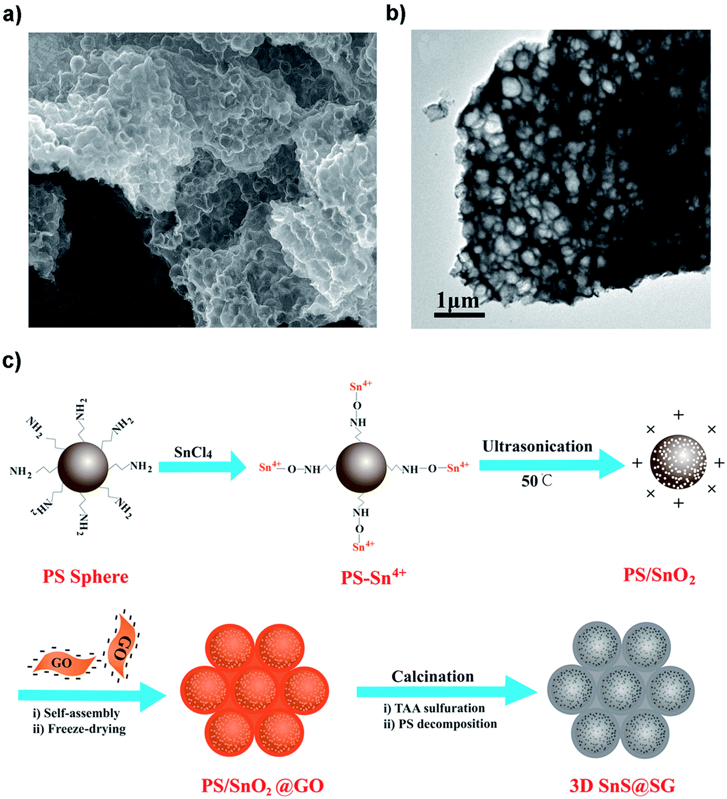
A variety of SnS/C composites are proposed to improve their cycling performance through the synergistic effect of well-dispersed SnS particles and carbon.75,82,86,87,93,99–101 Remarkably, in the past one decade, graphene has been viewed as one of the best conductive components for electrode materials because of its good support and high conductivity.47,102–104 Recently, SnS/graphene composites have also been synthesized by different methods.88,89,105,106 Zhao et al. prepared a 3D interconnected spherical graphene framework-anchored SnS nanoparticles (SnS@SG, Fig. 3a and b) by a template-assisted self-assembly method (Fig. 3c). The conversion/alloying process for SnS could be realized to be almost completely reversible in this 3D SnS@SG with a 99.7% reversibility of Li2S.90 The 3D SnS@SG demonstrated an excellent reversible capacity (800 mA h g−1 after 100 cycles at 0.1C and 527 mA h g−1 after 300 cycles at 1C; denoted as: 1C = 1000 mA g−1) and excellent rate capability (380 mA h g−1 at 5C). Hassan et al. synthesized a type of 1D single-crystal SnS nanorod rooted in S-doped graphene (SG) via a hot-chemistry structural phase transformation of SnS2 nanoplates. The SnS@SG composite delivered a reversible capacity of ∼850 mA h g−1 after 200 cycles at 100 mA h g−1 with a high CE of 97%, and a long-term capacity of 550 mA h g−1 after 1200 cycles at 500 mA h g−1 in the voltage window of 0.1–3.0 V. Additionally, it demonstrated a high volumetric capacity of ∼2350 mA h cm−3 (4 times greater than that of graphite).107 However, the introduction of graphene especially in the form of reduced graphene oxide (rGO) into the composite may cause low CE in the initial several cycles due to the defects/edges resulting in an irreversible capacity loss. The lithiation-assisted reduction or pre-occupation is found to be a vital strategy to solve the above problems for SnS/rGO composites. Zhao et al. exploited a few-layered SnS composite with lithium-integrated graphene sheets via a lithiation-assisted route to exfoliate and reduce the SnS2 precursor to SnS of a decreased lateral size decorated/restacked on the graphene surface. The SnS/rGO composite showed a higher first coulombic efficiency of 77.5% and a superior reversible capacity of 1016 mA h g−1 after 100 cycles at 100 mA g−1 as well as a favorable rate performance of 414 mA g−1 at 10 A g−1 in the voltage window of 0.01–3.0 V.108 The strategy of pre-occupying the defects of graphene provides an idea to solve the concerns on low initial coulombic efficiency (ICE) for practical batteries when using graphene-based composite electrodes.
 |
| | Fig. 3 (a) SEM and (b) TEM images of 3D interconnected SnS@SG with a uniform distribution of SnS nanoparticles (10–30 nm) on the spherical graphene framework; (c) schematic illustration of the synthetic procedure for 3D interconnected SnS@SG. Reproduced with permission.90 Copyright 2017, American Chemical Society. | |
2.1.3 Free-standing electrodes.
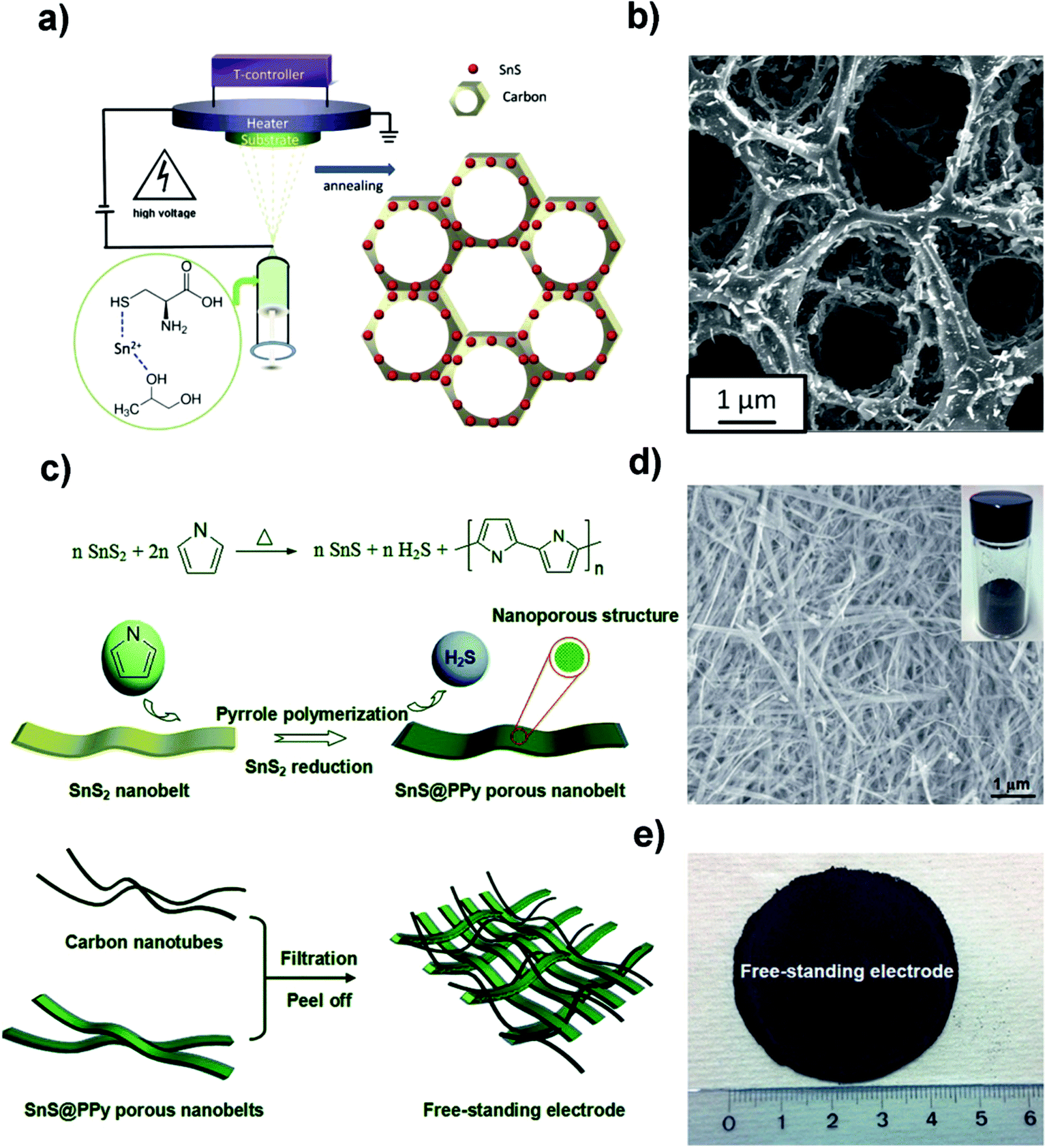
Designing free-standing electrodes is one of the hot research topics in the battery and capacitor fields owing to their easy fabrication and desirable binder-free characteristics. Recently, the Yu group deposited carbon-coated three-dimensional (3D) porous interconnected SnS/C composites on Ti foil by electrostatic spray deposition (ESD) using SnCl2 and L-cysteine as precursors, as shown in Fig. 4a.93 The synthetic method afforded the formation of orthorhombic crystalline SnS nanorods which were uniformly embedded in the amorphous carbon (Fig. 4b). This as-deposited 3D SnS/C structure provided a good electrical conductivity and buffering matrix for the SnS/C composite, which led to a discharge capacity of 535 mA h g−1 after 300 cycles with ∼80% capacity retention and high coulombic efficiency (CE). However, we should consider the loading amount of SnS/C on Ti foil, which would be lower than that of the commercial Cu foil in a normal process. After that, they also fabricated a free-standing SnS@polypyrrole-nanobelt/carbon-nanotube (SnS@PPy-NB/CNT) paper without using metal substrates via an in situ polymerization and restriction/bottom-up assembling method (Fig. 4c). The 3D paper with SnS@PPy nanobelts uniformly interconnected by CNTs (Fig. 4d and e) could deliver an overall electrode capacity of 757 mA h g−1 (891 mA h g−1 for the SnS@PPy) after 500 cycles at 1C (voltage range of 0.01–3.0 V) and a superior rate performance due to the highly conductive and porous properties of the network-like paper for electron/ion transfer.94 These studies not only provide insights into the novel fabrication methods for flexible electrodes, but also inspire us to explore other flexible film electrodes for different applications in the future.
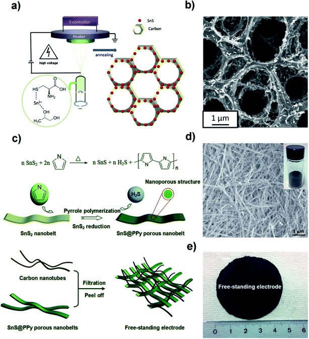 |
| | Fig. 4 (a) Schematic illustration of the electrostatic spray deposition (ESD) technique to fabricate a carbon-coated 3D porous interconnected SnS. (b) SEM image of the as-prepared SnS/C nanocomposite. Reproduced with permission.93 Copyright 2015, Wiley-VCH. (c) Schematic illustration of the in situ polymerization restriction method for the synthesis of well-conductive SnS@PPy porous nanobelt units and a facile bottom-up approach to manufacture the free-standing SnS@polypyrrole-nanobelt/carbon nanotube electrode. (d) Low-magnification SEM images of the SnS@PPy product; the inset shows the image of the product obtained after reduction and the in situ polymerization of pyrrole. (e) Photograph of the bottom-up free-standing paper electrode with a diameter of about 4.5 cm. Reproduced with permission.94 Copyright 2015, Royal Society of Chemistry. | |
2.2 SnS for Na-ion batteries
Although NIBs have some advantages as an alternative power source, i.e., the high abundance, low cost and suitable redox potential of Na compared to those of Li (Eo value for Na/Na+ = 2.71 V and for Li/Li+ = 3.05 V vs. SHE at 298 K, 1 M, 1 atm), the energy density of NIBs is still not attractive. This is attributed to the 55% larger ionic radius of Na and larger volume change thereof than that of Li, which causes low diffusion or sluggish sodium kinetics in both cathode and anode materials.81,109,110 To solve this issue, layered transition-metal sulfides have been intensively explored as a kind of appropriate electrode material for NIBs.41,51,53 Amongst them, SnS has attracted tremendous attention due to its high theoretical sodium storage capacity based on a conversion-alloying mechanism. Owing to the inherent larger radius of Na+ (0.102 nm) compared with Li+ (0.076 nm), the reaction of SnS with Na is complicated because it undergoes a larger volume change than the reaction of SnS with Li. In order to improve the Na storage properties of SnS, several methods, some of which have been mentioned above, have been exploited for optimizing the nanostructures, enhancing the conductivity, and providing a buffering matrix for large volume variation.43,45,93,111–117
2.2.1 Structurally designed SnS/C composites as the anode.
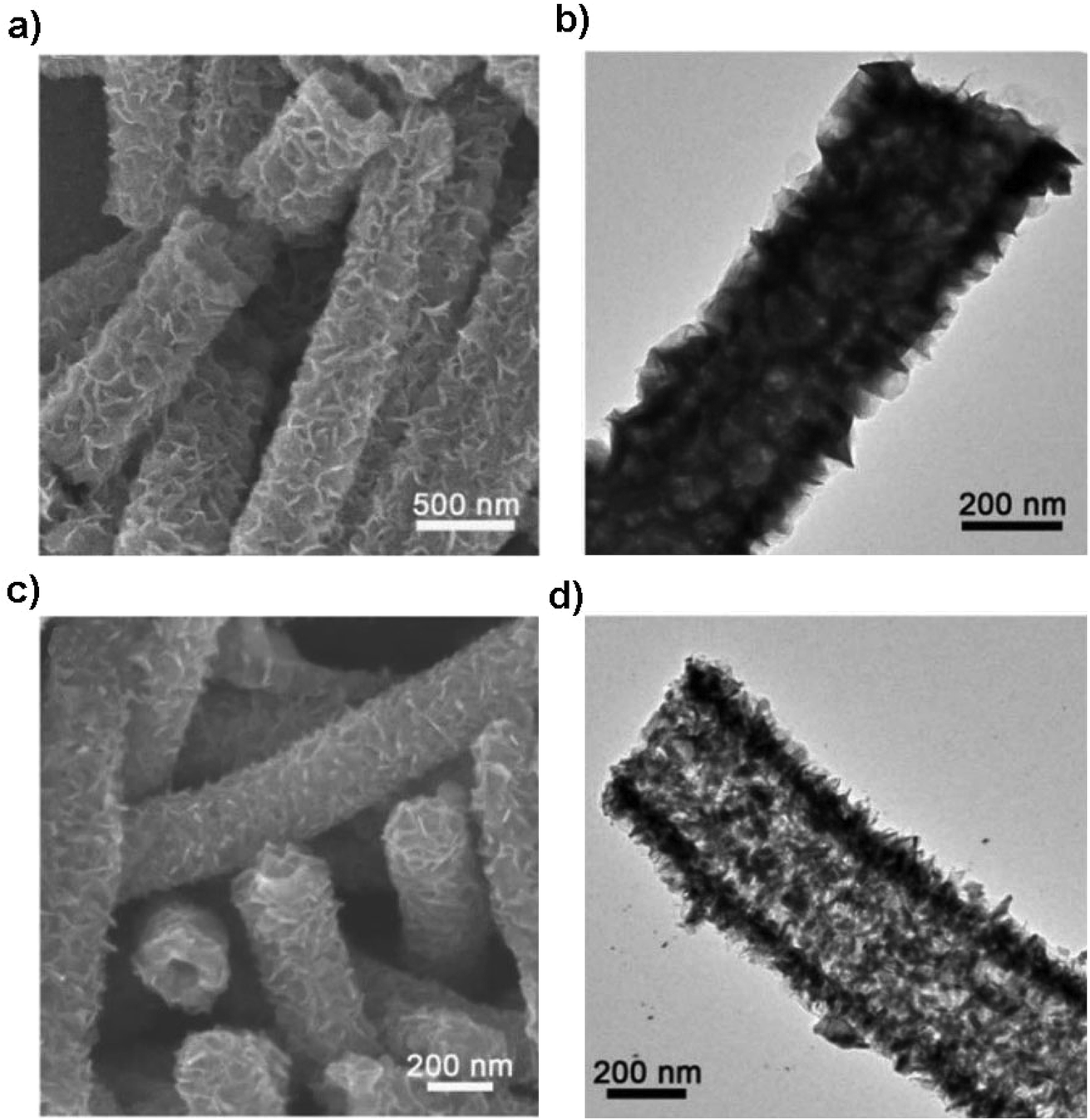
Structural design is demonstrated to be effective in developing high-performance SnS/C composite anodes for NIBs. The Lou group designed a hierarchical nanotube constructed by carbon-coated ultrathin SnS nanosheets that showed fast capacitive Na-ion storage properties. The hierarchical SnS nanotubes composed of ultrathin nanosheets (Fig. 5a and b) were solvothermally synthesized on a MoO3 nanorod template with the assistance of PVP, followed by the selective removal of the template with ammonia. After that, the carbon-coated SnS nanotubes were in situ prepared by simply introducing glucose into the reaction system. The hierarchical SnS@C nanotubes (Fig. 5c and d) exhibited a good cycling performance of 440 mA h g−1 after 100 cycles at 0.2 A g−1 and a superior rate capability of 290 mA h g−1 at 5 A g−1 due to the unique structural merits.118 And by introducing carbon frameworks, Choi et al. prepared hierarchical SnS/C microspheres with 5 nm thick amorphous carbon coated SnS cubic nanocrystals decorated around the carbon core via a spray pyrolysis process (Fig. 6a). The hierarchical SnS/C microspheres could deliver a discharge capacity of 433 mA h g−1 in the potential window of 0.001–2.0 V and a capacity retention of 89% (measured from 2nd cycle), which is only 25 mA h g−1 and 5% for bare SnS (Fig. 6b–e).119 Wang et al. embedded SnS nanoparticles (NPs) in microspherical carbon via an industrial scalable and simple rapid aerosol spray pyrolysis approach. The 5 nm-SnS/C composite delivered an initial charge capacity of 561 mA h g−1 at 1 A g−1 and maintained a reversible discharge capacity of 518 mA h g−1 after 200 cycles at 1 A g−1. It also showed a high rate capacity of 429 mA h g−1 at 3 A g−1 and 315 mA h g−1 at 5 A g−1 due to the uniform dispersed ultrafine nanoparticles (e.g., better than 20 nm SnS) in the stable carbon matrix which buffers the volume expansion and prevents the aggregation of the active nanoparticles.120 Additionally, the decoration of 3D macroporous carbon architectures with interconnected networks favors transport kinetics of both electrons and sodium ions. For example, the hybrid of SnS nanoparticles supported on NaCl-crystal-templated N-doped carbon exhibited a high reversible long-term cycling capacity of 484 mA h g−1 at 1 A g−1 and 322 mA h g−1 at 5 A g−1 over 1000 cycles (active material loading of 1.5 mg cm−2), and of 428 and 331 mA h g−1 with an increased mass loading of 2.8 and 4.3 mg cm−2, respectively.121
 |
| | Fig. 5 SEM and TEM images of (a and b) the hierarchical SnS nanotubes and (c and d) SnS@C nanotubes constructed by carbon-coated ultrathin SnS nanosheets as the anode for NIBs via a facile templating method. Reproduced with permission.118 Copyright 2017, Wiley-VCH. | |
 |
| | Fig. 6 (a) Schematic formation process of the SnS–C microspheres in a one-pot spray pyrolysis. The electrochemical properties of the SnS and SnS–C microspheres for NIBs: (b) CV curves, (c and d) initial charge/discharge profiles and cycling performance at 0.5 A g−1, and (e) rate performance of the SnS–C microspheres prepared at 900 °C. Reproduced with permission.119 Copyright 2015, Springer. | |
Since the functionalization of the carbon frameworks such as carbon nanosheets not only strengthens the interaction with SnS but also enhances the conductivity and pseudocapacitance of the nanocomposite, which was revealed by further kinetic (quantitative capacitive) analysis for fast Na-ion storage at high rates, the Zhou group designed a hybrid structure of oriented SnS nanoflakes bound on S-doped N-rich nanosheets via sol–gel and hydrothermal routes. The nanostructured SnS composite as an anode for NIBs delivered a high reversible capacity of 654 mA h g−1 with a stable capacity retention of ∼98% after 100 cycles at 1 A g−1 and showed a remarkable high rate capacity of 251 mA h g−1 at 20 A g−1. The high performances of this composite were attributed to the pseudocapacitive contribution due to the unique heteroatom doping and ordered oriented layered structure, which also offered an insight into developing advanced structures for NIBs.122 By increasing the affinity of SnS architectures to conducting substrates, Xiong et al. further designed a type of SnS nanoparticles electrostatically anchored on a 3D N-doped graphene network via the introduction of a polycationic PDDA (polydiallyldimethylammonium chloride) mediator for stronger combination and thus a more stable electrode structure and an enhanced discharge capacity and cycle life. The as-prepared composite in a half cell showed a capacity of 585.3 mA h g−1 for 1000 cycles at 2 A g−1 with a capacity retention rate of 87.1%, and for a full NIB paired up with an Na3V2(PO4)3 cathode, the anode composite material also maintained a reasonably high capacity of 414.6 mA h g−1 for 300 cycles at 1 A g−1 within the voltage window of 3.0–0.8 V with a retention rate of 85.8%. The enhanced combination may direct a viable solution for the development of hybrid anodes for long cycle life NIBs.123
2.2.2 SnS/graphene composites as the anode.
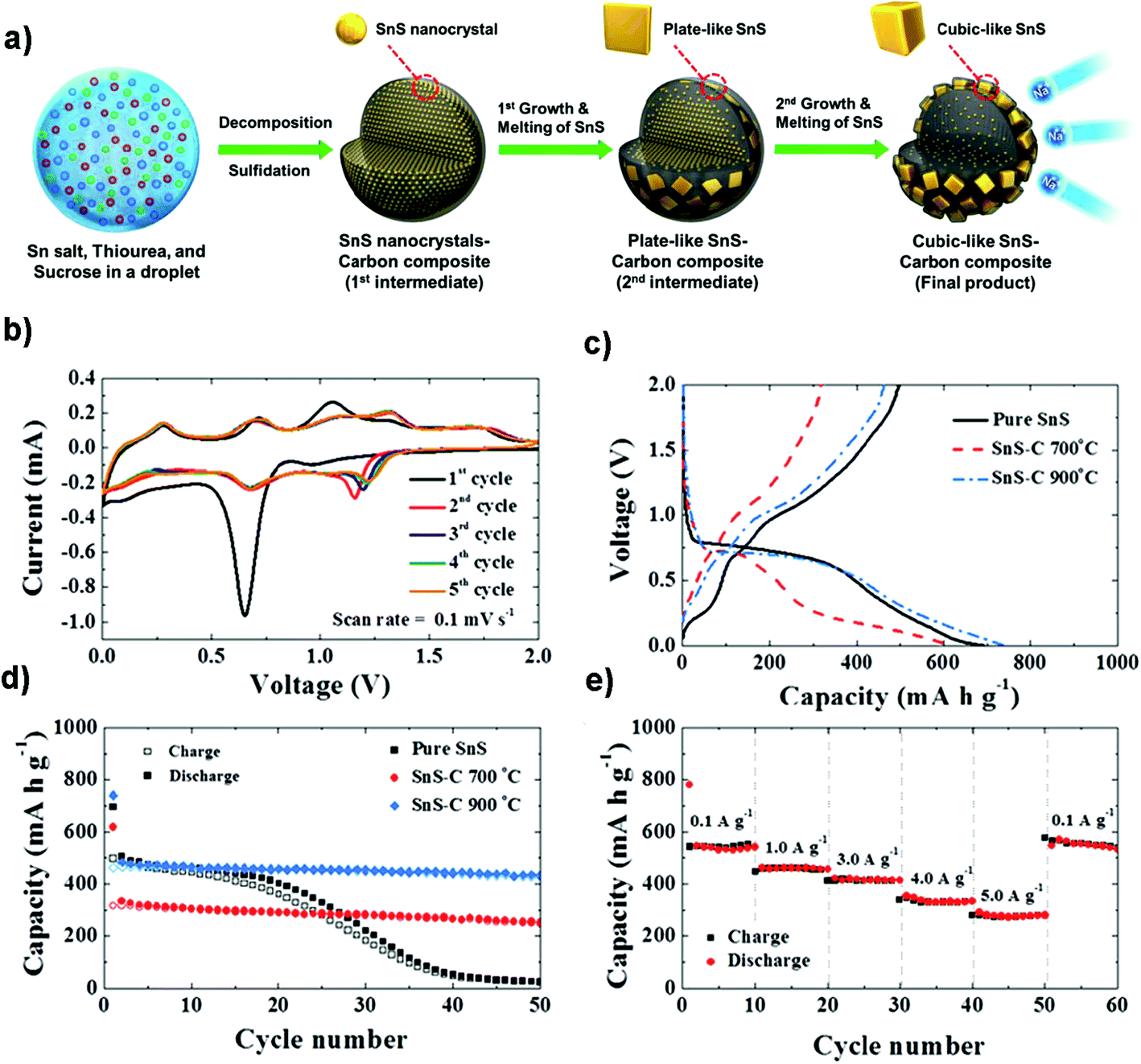
The introduction of graphene to obtain dispersed SnS architectures on a 2D conductive matrix could also greatly improve the electrochemical performance of SnS. Graphene provided a free area between adjacent nanoparticles and served as an effective buffer to tolerate huge volume changes during cycling. The Guo group fabricated a SnS@graphene hybrid nanocomposite via by a facile structure phase transition method (Fig. 7a), which is built from 2D SnS and graphene nanosheets as complementary building blocks (Fig. 7b and c). It exhibited an outstanding specific capacity of 940 mA h g−1 and an impressive rate capability of 492 and 308 mA h g−1 after 250 cycles at the current densities of 810 and 7290 mA g−1 (Fig. 7d), respectively, using an alternative PAA-CMC binder and electrolyte additive fluoroethylene carbonate (FEC). The two-structural-phase transformation (i.e., orthorhombic-SnS ↔ cubic-Sn ↔ orthorhombic-Na3.75Sn) during the charge/discharge process may also contribute to the good structural stability and outstanding cycling stability, which is different from the three-structural-phase transformation (i.e., hexagonal-SnS2 ↔ tetragonal-Sn ↔ orthorhombic-Na3.75Sn) that SnS2 experienced.70
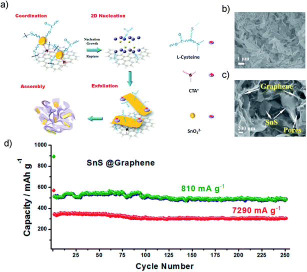 |
| | Fig. 7 (a) Schematic diagram illustrating the hydrothermal preparation of the hybrid tin sulfide and graphene architecture. (b and c) Typical SEM images of the SnS@graphene architecture at different magnifications, which reveal the porous structure and thin walls containing both SnS and graphene nanosheets. (d) long cycling performances of the SnS@graphene electrode at different current densities. Reproduced with permission.70 Copyright 2014, American Chemical Society. | |
2.2.3 Free-standing anode.
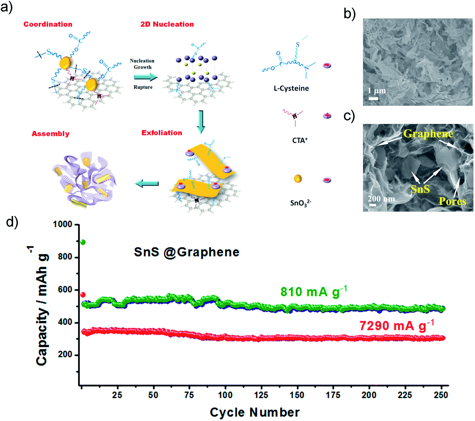
Although achieving faster charging and higher power density is still challenging for most NIB electrodes because of sluggish sodiation kinetics, the Shen group has proposed a 3D graphene-supported array of SnS nanosheets for ultrafast and high-capacity Na-ion storage and studied the pseudocapacitive mechanism (Fig. 8a). The graphene foam supported nanoarray anode, where the open framework consisted of kinetically favorable Na-ion channels, delivered a high reversible capacity of ca. 1100 mA h g−1 at 30 mA g−1 and ca. 420 mA h g−1 at 30 A g−1, which are superior to its performance in LIBs. This kind of 3D electrode design by surface-dominated redox reactions (or maximized extrinsic pseudocapacitance contribution) may also show inspiration for other layered electrodes of high-performance NIBs as well as LIBs (Fig. 8b–d).42 Choi and coworkers designed a paper-type nanohybrid anode (PNA) comprised of uniform tetrahedral SnS nanocrystals (∼500 nm) and acid-treated multi-walled carbon nanotubes (MWCNTs). The nanohybrid anode delivered a high capacity of 946 mA h g−1 after 50 cycles at 300 mA g−1, and when paired up with a Na1.5VPO4.8F0.7 cathode it demonstrated a stable cycling capability and a high energy density of 256 W h kg−1 and a power density of 471 W kg−1. It is amazing that the PNA showed a stable low-voltage-plateau (i.e., at low voltages < 0.1 V vs. Na+/Na) capacity of ∼500 mA h g−1 after 250 cycles at 300 mA g−1 in a narrow voltage window of 0.01–0.5 V versus Na+/Na. It is also noteworthy that the PNA delivered a high first coulombic efficiency of ∼90% and above 99% during subsequent cycles, which is mainly ascribed to the adoption of a novel DEGDME-based electrolyte, i.e., NaPF6 dissolved in diethylene glycol dimethyl ether than traditional EC/DEC. Thus the paper-type nanohybrid anode architectures may provide a strategy for Na-ion batteries with significantly improved energy and power densities, while preventing the low CE and unfavorable voltage properties.104
 |
| | Fig. 8 (a) Schematic illustration of the high-rate Na-ion storage of the layered SnS/graphene foam nanohoneycomb architecture via rapid sodiation on a surface dominated by an extrinsic pesudocapacitance mechanism. (b) The percentage of capacitive contribution (red) at different scan rates and (c) taking the capacitive (red) and diffusion-controlled (blue) contribution at 0.8 mV s−1 as an example. (d) Galvanostatic profiles of the as-prepared NIB and LIB electrodes at rates of 30 mA g−1 and 7 A g−1, and the inset showing that for high-rate LIBs it also takes on a much higher capacitive contribution (e.g., 75% at 0.8 mV s−1) over the diffusion-controlled process (i.e., insertion, conversion and alloying). Reproduced with permission.42 Copyright 2016, Nature Publishing Group. | |
2.2.4 SnS-based heterostructures as the anode.
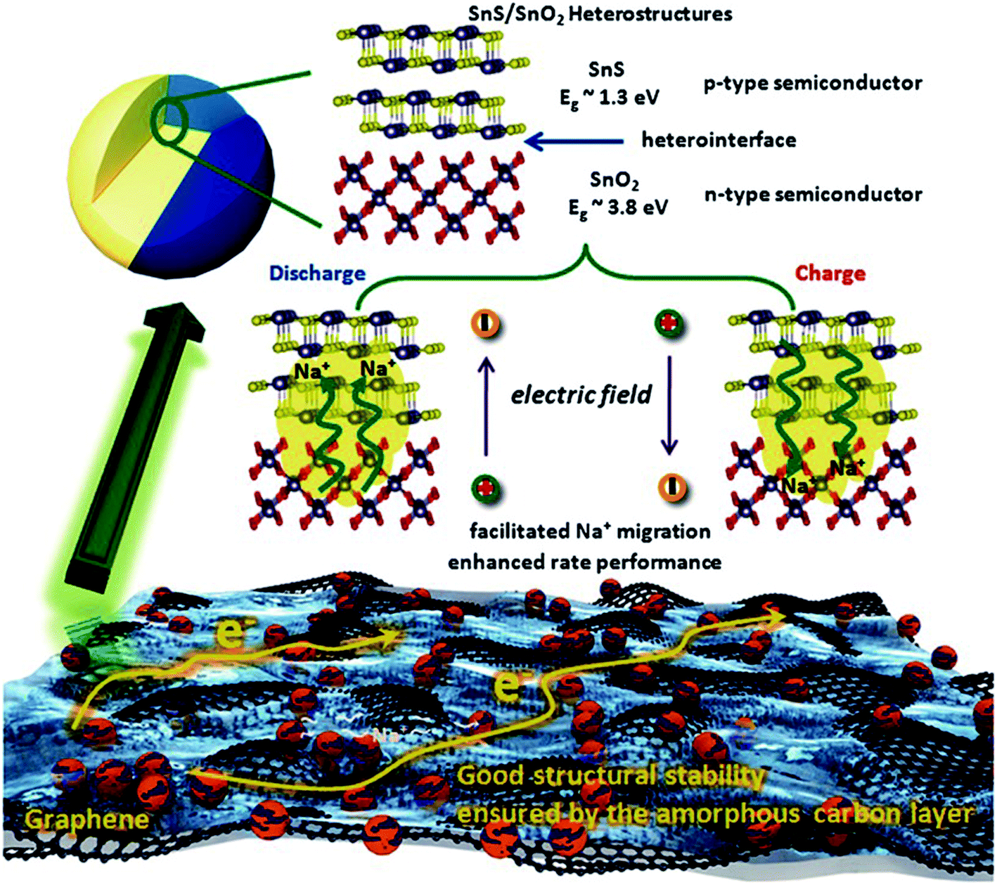
The physical structure and synergy of the transition metal sulfides or oxides also play key roles in determining their performances in energy storage systems.124–129 The Guo group found that the interface effect of the SnS/SnO2 p–n heterostructure could boost the charge transfer kinetics for high-rate NIBs (Fig. 9). This heterostructure delivered a reversible capacity of 409 mA h g−1 at 810 mA g−1 (∼73% retention) and ca. 360 mA h g−1 at 2430 mA g−1 (∼76% retention) after 500 cycles, showing outstanding cycling stability.130 And a yolk–shell structure with a “ball-in-ball” morphology shows several advantages including a short ion diffusion length, void space for volume expansion and tunable energy density by controlled cores of such micro- or nano-architectures.44,131,132 Choi et al. reported a multicomponent metal sulfide material with a yolk–shell structure. The SnS–MoS2 composite microspheres exhibited a high structural stability during Na insertion/desertion processes and delivered a discharge capacity of 396 mA h g−1 after the 100th cycle with a capacity retention of 89%, much higher than that of the related dense-structured analogue, which may be attributed to the synergetic effect of the yolk–shell structure, uniform dispersion, and low charge-transfer resistance even after long-term cycling.124 Therefore, the synergetic method is a promising strategy for next-generation high-performance batteries.
 |
| | Fig. 9 Schematic illustration of the enhanced high rate capacity mechanism of the p–n heterostructures (C@SnS@SnO2@graphene) with boosted charge transfer in the NIB system. Reproduced with permission.130 Copyright 2016, Wiley-VCH. | |
3. SnS2
SnS2, with a large interlayer spacing of c = 0.59 nm, is considered as a promising anode material for LIBs and NIBs because of its unique layered structure, high theoretical capacity (1231 mA h g−1 for LIBs and 1136 mA h g−1 for NIBs) and low redox potentials.90,133 However, the pristine compound has a relatively poor conductivity and experiences large volume change during electrode reactions. This could cause electrode pulverization, and further result in poor cycling performance of SnS2 materials. To address this issue, some strategies have been applied, i.e., the morphological control,116,134–150 the hybridization of SnS2 with graphene and other alternative conductive components,50,125–127,151–164 SnS2-based heterostructures, and the structural design of the SnS2 electrode.119,165–169
3.1 SnS2 for Li-ion batteries
3.1.1 Lithium storage mechanism studies in SnS2.
From the structural chemistry point of view, the interlayered SnS2 structure with octahedral interstitial sites is energetically favorable for lithium intercalation, i.e., the Li atom may diffuse from one octahedral interstitial site to the neighboring one via the tetrahedral interstitial site. Obviously the expansion of the interstitial interlayer spacing and reducing the dimensions of SnS2 are beneficial for decreasing the diffusion barrier; the former can be realized by doping with elements such as Ce, Se or Mo.82,170,171 For the latter, it will not only significantly lower the lithium diffusion barrier but also maintain a considerable binding energy due to the edge effect, and thus the low-dimensional SnS2 structures (e.g., nanoribbons/nanobelts and nanoplates) will possess an enhanced lithium binding strength simultaneously with increased Li+ mobility, and also improve the capacity of promising anode materials with high power density and fast charge/discharge rates.140,172–174
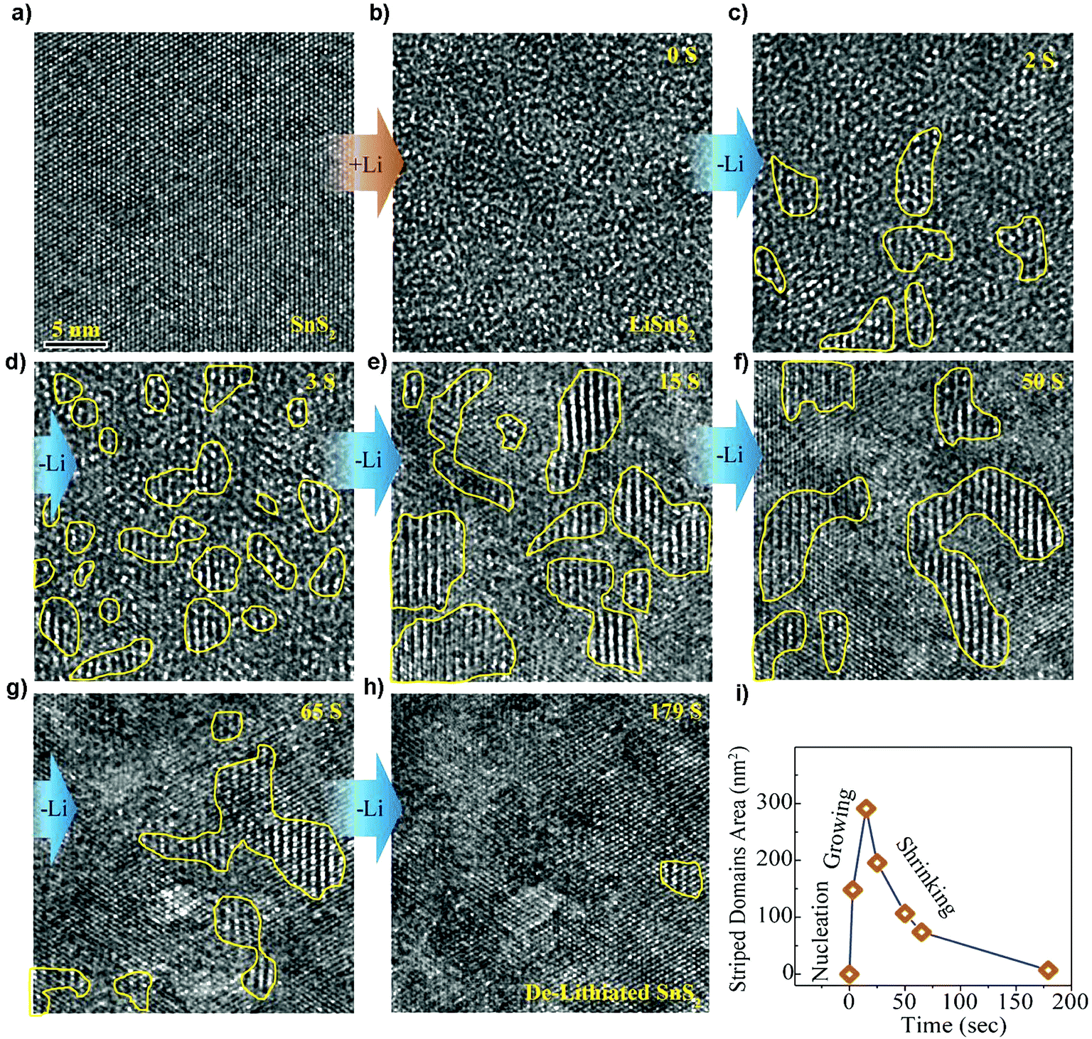
The direct observation of the structural stability and transition of SnS2 during electrochemical cycling using in situ HRTEM has clearly revealed the microstructural evolution upon lithiation and delithiation.175 The two-step reaction in the lithium intercalation of layered crystalline SnS2 by irreversible formation of metallic tin and amorphous lithium sulfide as well as the reversible transformation of metallic tin to Li–Sn alloys can be perceptually acknowledged. And it reveals a self-assembled composite framework, with crystalline Sn nanoparticles well-arranged within the amorphous Li2S matrix that was formed during the former irreversible conversion reaction. This type of nanoscale framework partly hinders agglomeration of Sn particles, thus benefiting a sufficient electron pathway, leading to an enhanced cycling stability, making it a high-performance anode material for LIBs. Furthermore, by tracking Li insertion/extraction in the van der Waals interaction dominated layered SnS2 nanostructures (Fig. 10), the Li insertion was found to occur via a fast two-phase reaction to form expanded and defective LiSnS2 (Fig. 10a and b), while the Li extraction involves a relatively slow heterogeneous nucleation process by forming kinetically favorable and structurally stable intermediate superstructure Li0.5SnS2 domains of 1–4 nm (Fig. 10b–h). Such asymmetric reaction pathways (Fig. 10i) provide intuitive insights into the electrochemical mechanism of the layered electrode materials and origins of voltage hysteresis thereof.176 First-principles calculations of the lithium sorption mechanisms in SnS2 agreed with the experimental results and in situ observations. It showed that beyond the conversion limit and alloying in SnS2 the interfacial storage is also contributed by high-capacity Li sorption. Therefore, the observed capacity beyond stoichiometric limits of metal oxide and metal sulfide materials may be attributed at least partially to the universal high-capacity interfacial storage mechanism. It was also concluded by calculations that the SnS2 showed the least volume expansion and further supports the concept that it is a promising anode material for LIBs.177
 |
| | Fig. 10 HRTEM tracking ([111] direction) of the intermediate superstructure evolution during Li extraction. (a and b) The super-fast Li insertion from pristine state SnS2 to intercalated state LiSnS2. (b–h) The structural evolution from Li intercalated state LiSnS2 to pristine state SnS2. (i) The total striped domain area plotted as a function of time from the selected region showing asymmetric reaction pathways. Reproduced with permission.176 Copyright 2016, American Chemical Society. | |
3.1.2 SnS2/graphene composites as the anode.
Compared with SnS, the incorporation of SnS2 with graphene may deliver better rate capacity and superior cycling performance, since 2-fold Li2S per Sn will be formed in SnS2 compared to SnS, thus leading to a small reversible volume change.47,68,153,154,178–181 However, the vulnerable restacking problem of SnS2 may result in a poor initial reversible capacity and deteriorative cycling stability. Furthermore, the passivation and charge transport issues between the interfaces of the active phase and the conductive additive/substrate will also largely affect the energy/power density and cycling performance for practical applications.182 To address these problems, various integrated approaches have been adopted. For example, Mei et al. fabricated a cost-effective composite structure of ultrasmall SnS2 nanocrystals (3–4 nm) uniformly decorated on flexible rGO via a simple refluxing approach, which showed a superior electrochemical performance with a specific capacity of up to 1034 mA h g−1 (voltage window 0.001–2.5 V) after 200 cycles at 0.1C (1C = 645 mA g−1) and an excellent capacity retention of 570 and 415 mA h g−1 for up to 450 cycles at 3C and 5C, respectively. The as-prepared nanoarchitecture reduced the electrode polarization and accelerated the electron and ion transport, which are very beneficial for its excellent performance as a promising anode material for advanced LIBs.183 Chang et al. developed a few-layer SnS2/rGO hybrid by a solution-phase method using L-cysteine as a sulfide source and complexing and reducing agent. The few-layer SnS2 with defects or a disordered architecture anchored on the graphene surface showed a robust composite structure with synergistic interactions between them as well as improved electrical conductivity and electron transfer, which is favorable for the excellent capacity of up to 920 mA h g−1 (potential range of 0.01–1.5 V) with good cycling stability and high-rate performance.184 Some related studies showed that the SnS2/N-doped rGO composite exhibited high performances as well, e.g., by delivering a specific capacity of 562 mA h g−1 (potential range 0.01–1.3 V) at the 200th cycle at 0.2 A g−1 rate,68 or a high reversible capacity of 1407 mA h g−1 (potential range 0.01–3.0 V) at 200 mA h g−1 after 120 cycles.185 Additionally, Gao et al. designed a nanoarchitecture of SnS2 nanoplates vertically grown on rGO nanoribbons for high-performance lithium storage and full Li-ion cells. The nanohybrid showed an excellent capacity of 823 mA h g−1 (potential range 0.01–3.0 V) after 800 cycles at 400 mA g−1 and a good rate performance with CE larger than 99%. When paired up with a commercial LiCoO2 cathode, it delivered a high capacity of 642 mA h g−1 at 200 mA g−1 and a stable long-term cycling with a full-cell output working voltage of 3.4 V.174
3.1.3 SnS2-based composites without graphene as the anode.
Besides various carbon materials,168,186–192 other conductive components such as polyaniline (PANi), polypyrrole (PPy), 2D MXenes, and vanadium nitride (VN) are also investigated.166,193,194 For example, by in situ oxidation polymerization of aniline on the surface of ultrasonic exfoliated SnS2 hexagonal nanoplates, the 2D SnS2@PANi nanocomposite as an anode material for LIBs showed a higher initial reversible capacity of 969 mA h g−1 and enhanced cyclability of 731 mA h g−1 after 80 cycles, as well as an extraordinary rate capacity of 356 mA h g−1 at 5 A g−1.193 A sandwich-like SnS/PPy structure was synthesized by Liu et al. through a microcube-templated and hydrothermal in situ polymerization route (Fig. 11a–c) for enhancing the electronic conductivity and Li-ion diffusion kinetics as well as providing stable and flexible framework for volume expansion in battery electrodes (Fig. 11d). The fabricated ultrathin nanosheet hybrid with large interfacial tension as an anode material equally showed an extraordinary reversible capacity of ca. 1000 mA h g−1 at 0.1C, good rate capacity and a high long-cycle capacity of 703 mA h g−1 (potential range of 0.01–3.0 V) at 1C after 500 cycles.194 By combination of the VN nanofiber substrate with layered SnS2, a competitive cycling capacity of 791 mA h g−1 after 100 cycles with the capacity retention of 97% was achieved, as well as a high-rate discharge capacity of 349 mA h g−1 at 13 A g−1 after 70 cycles. The excellent performance was attributed to the conductive and fibrous VN as the substrate support, which provided short Li-ion/electron pathways and structural/mechanical stability, accommodated large volume variation, and contributed some capacity.166
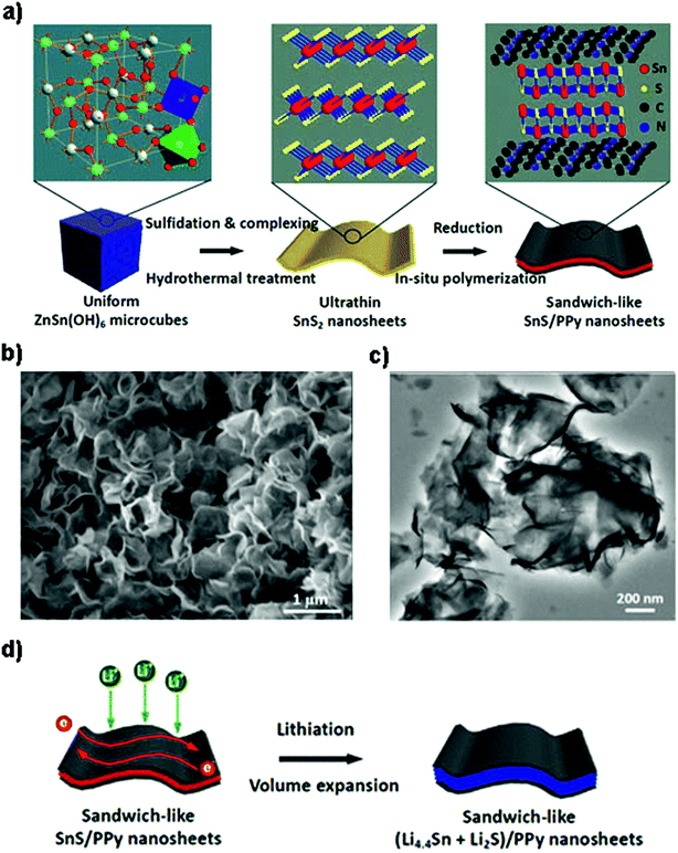 |
| | Fig. 11 Schematic illustration of (a) the fabrication of sandwich-like SnS/PPy ultrathin nanosheets from ZnSn(OH)6 microcubes as the tin source. (b and c) SEM and TEM images of the ultrathin nanosheet-like SnS/PPy derived from an in situ polymerization process, showing a curved 2D morphology with a smooth surface. (d) The lithiation process of the as-prepared nanohybrid with sufficient electron conduction paths and electroactive SnS volume expansion. Reproduced with permission.194 Copyright 2016, American Chemical Society. | |
3.1.4 SnS2-based heterostructures as the anode.
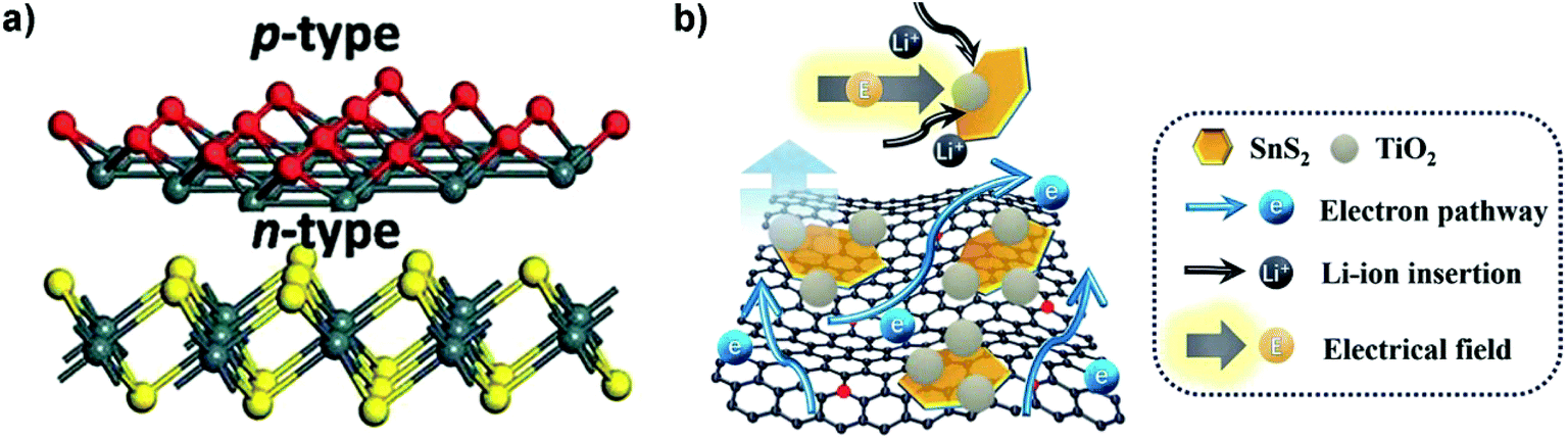
The interfacial advantages of p–n heterojunctions were also utilized to improve the energy storage performances of SnS2 based devices.195,196 For instance, Zhang et al. constructed a p–n heterostructure of p-type SnO thin layers on n-type SnS2 nanosheets with defective heterointerfaces (Fig. 12a) via plasma treatment of SnS2 for enriched surface defects and embedded/internal charge transfer which are essential for high-performance LIBs. The created heterointerfaces of the p–n junction decreased the charge transfer resistance and significantly improved the Li-ion and electron diffusion kinetics, and the SnS2/SnO nanocomposite delivered an extraordinary discharge capacity of 1496 mA h g−1 at 200 mA g−1 and a long-term reversible capacity of 998 mA h g−1 after 200 cycles.197 A ternary SnS2/TiO2/N-doped-rGO heterostructure composite (Fig. 12b), comprised of few-layered ultrafine SnS2 nanoparticles (NPs) of abundant defects decorated with TiO2 NPs in intimate contact, was fabricated via a two-step solution process and showed superior LIB capability. It can be mainly ascribed to the synergetic effects of rapid electron/ion transport and reduced particle aggregation/detachment as well as the improved charge transfer at the SnS2/TiO2 heterointerfaces driven by a built-in electric field. The dual-confinement based on the N–Sn bonds and TiO2 decoration via pinning SnS2 nanoparticles for enhanced anchoring on the N-doped graphene substrate also improved the electrode structural integrity and cycling stability, which may provide inspiring insight into the development of heterojunction-based composite materials for Li and post-lithium ion batteries.198 The systematic understanding of some catalysts such as Mo on the alloying type metal sulfide anode may provide a new insight into high energy density anodes. For the SnS2/MoS2 system, i.e., a hierarchical nanostructure of MoS2-decorated vertical SnS2 nanosheets that were self-assembled on the 3D graphene foam, the introduced Mo is characterized by ex situ TEM and XPS analysis to verify its role in promoting the reversible conversion of Sn to SnS2, thus further improving the Li storage capacity of SnS2 and the initial coulombic efficiency (ICE) of the device via a conversion reaction along with the alloying–dealloying reaction. A similar phenomenon has also been observed in some analogous systems such as SnO2/Co3O4/rGO and GeO2/Ge/C.126 Additionally, fabrication of heterostructures with tailored properties by controlled stacking of these 2D atomic crystals on top of each other is another promising approach to create smart devices or for novel applications.30
 |
| | Fig. 12 (a) Schematic illustration of the SnS2/SnO p–n heterointerface-containing nanoarchitecture via plasma treatment. Reproduced with permission.197 Copyright 2017, Royal Society of Chemistry. (b) Schematic illustration of the structural characteristics of the ternary SnS2/TiO2/N-doped-rGO heterojunction nanocomposite as the anode for superior LIBs. Reproduced with permission.198 Copyright 2017, Royal Society of Chemistry. | |
3.1.5 Free-standing anode.
Flexible or stretchable energy-storage devices toward practical applications such as the ever-growing market of wearable electronics have attracted great interest.199–203 The confinement of active materials, for example, in free-standing conductive frameworks is promising for flexible and binder-free electrodes for wearable electronics. Zhang et al. fabricated a 3D nanoporous graphene/CNT hybrid with layered SnS2 nanosheets homogenously dispersed and confined in the highly conductive framework for highly reversible Li storage, which effectively prevented their stacking/aggregation and assisted in facilitating ion transfer across the interfaces and showed an enhanced capacity of 1118 mA h g−1 at 0.1 A g−1 and an excellent rate capacity of 635 mA h g−1 at 2 A g−1 with favorable cycling stability.204 An in situ 3D hierarchical self-supported MWCNTs/SnS2-nanosheet hybrid electrode was designed through a simple two-step vapor-phase transport procedure, i.e., thermal evaporation of commercial SnS precursors for SnS2 nanosheets on a MWCNT deposited Ni/Ti-coated stainless steel current collector. The as-prepared anode exhibited superior rate capabilities of 480 and 420 mA h g−1 (potential window 0.2–1.3 V) even at a very high C-rate of 5C and 10C (i.e., charging in 6 min for the latter), respectively, which may be attributed to the superior electronic/ionic conductivity and laterally confined layered nanocrystals (LCLNs) with a large surface area and finite lateral sized and enhanced open-edge morphologies.140,205 Kong et al. fabricated a mechanically robust, free-standing SnS2@graphene nanocable network for high-performance lithium storage via encapsulating the electrospun fibers of SnS2 nanosheets with CVD-coated graphene layers (Fig. 13a and b). The easy access to the electrolyte for the active materials and continuous conductive network (Fig. 13c and d) for the whole binder-free electrode endows it with an excellent long-term cycling specific capacity of 720 mA h g−1 after 350 cycles at 0.2 A g−1 with a 93.5% capacity retention and a high rate capability of 580 mA h g−1 at 1 A g−1.206 A flexible SnS2-NPs/S-doped rGO composite buckypaper as an anode for LIBs and NIBs was exploited by Zheng et al. The composite delivered a reversible capacity of 1078 at 0.1 A g−1 for LIBs, and showed an outstanding rate capacity and cycling stability with 532 mA h g−1 over 600 cycles at 5 A g−1 for LIBs.207
 |
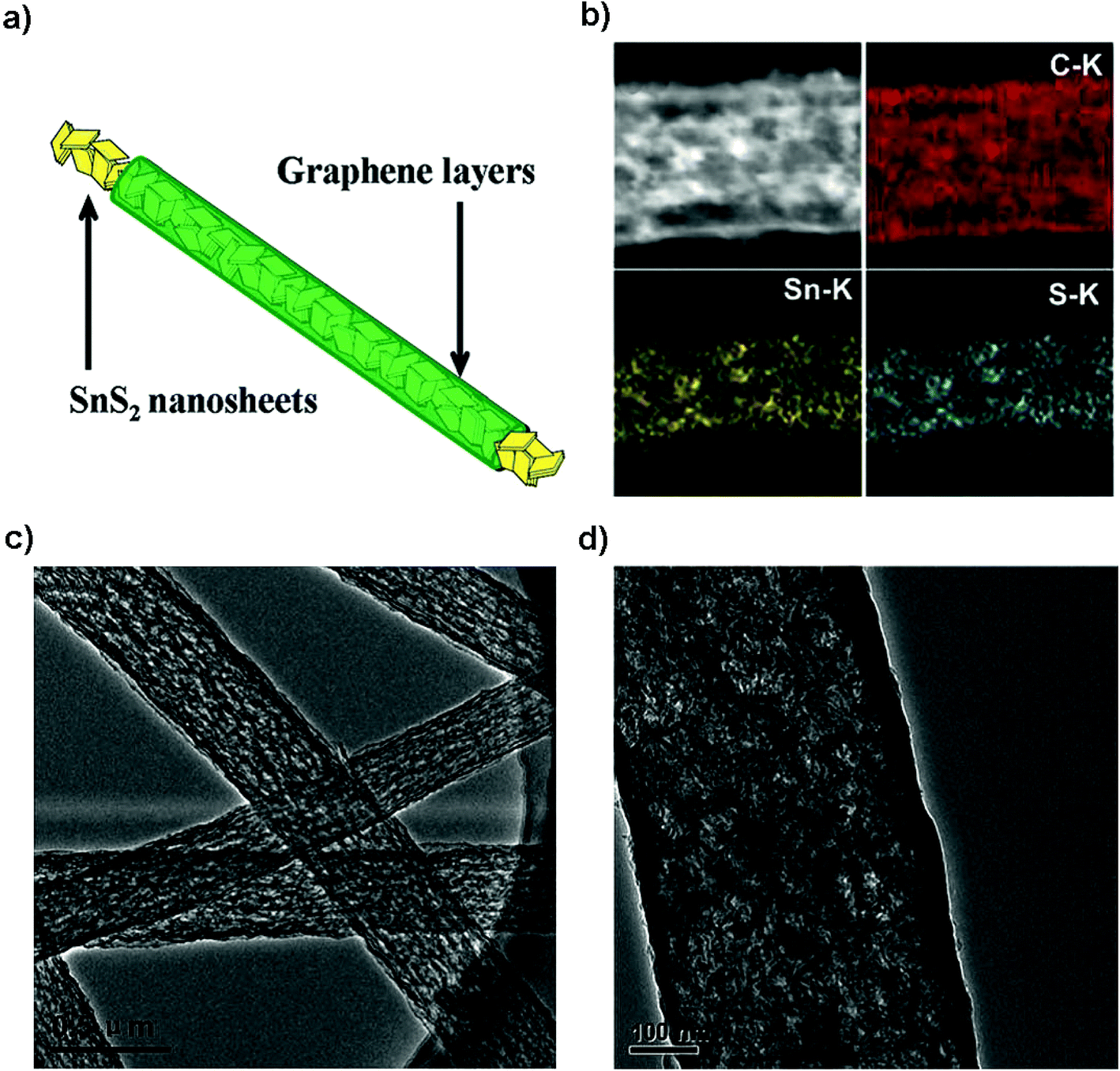
| | Fig. 13 (a) Electrode design, (b) mapping and (c and d) TEM images of the SnS2@graphene nanocable network for the high-performance free-standing and mechanically robust LIB anode. Reproduced with permission.206 Copyright 2014, Royal Society of Chemistry. | |
3.2 SnS2 for Na-ion batteries
3.2.1 Sodium storage mechanism studies of SnS2.
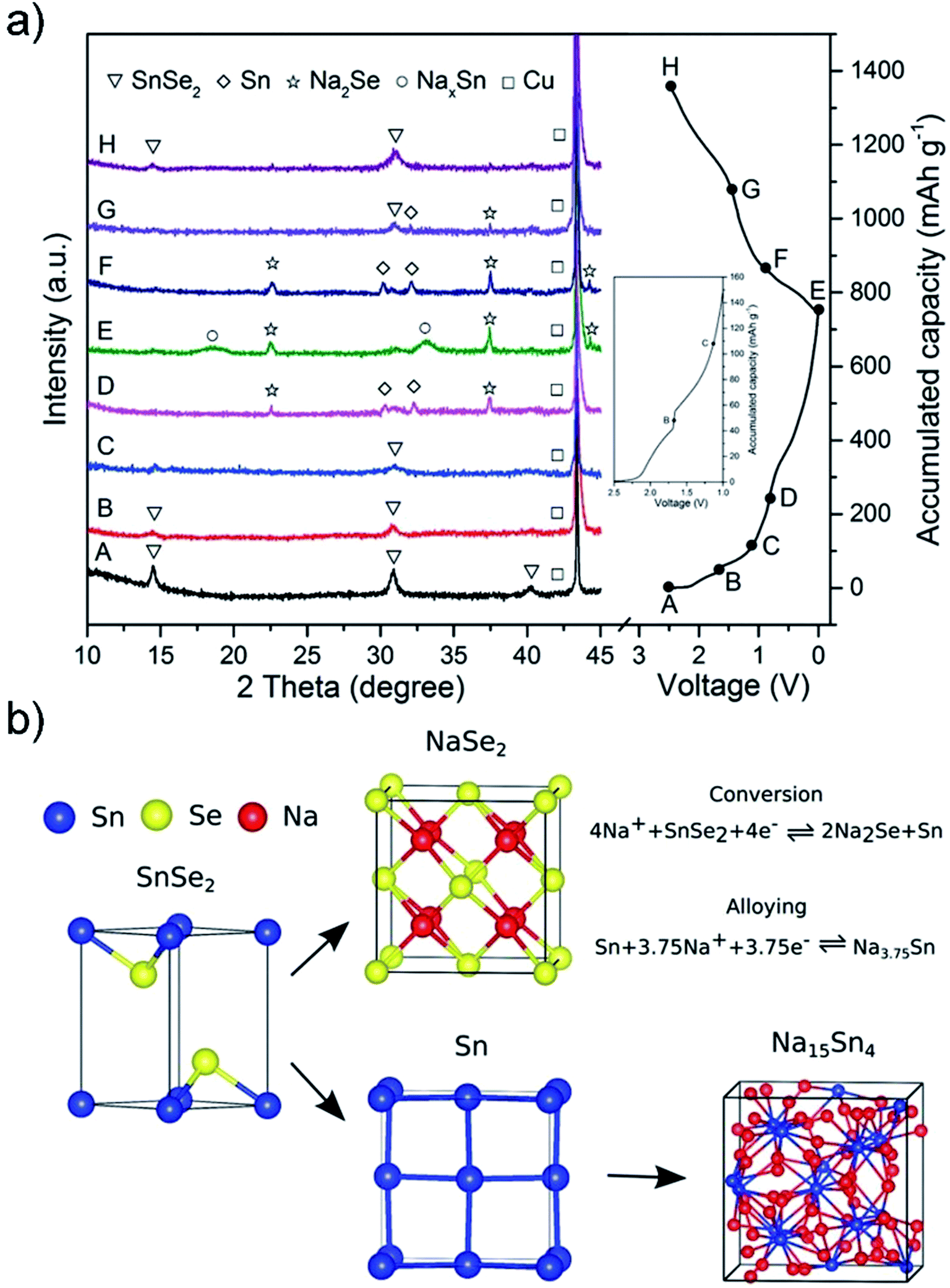
One of the main challenges for the commercialization of NIBs is to find suitable anode materials, since the larger size of Na ions, compared to Li ions, precludes their intercalation into typical low-cost graphite materials.151 Advantages such as high storage capacity, low half-cell voltage, high binding energy of the sodium adatom, and a low activation energy barrier for sodium diffusion as well as nontoxic and earth-abundant merits make SnS2 a favorable candidate as a highly promising anode material for rechargeable NIBs.152 For Na-ion batteries, the SnS2 exhibits a combined conversion and alloying/de-alloying mechanism, which is quite different from that of some other layered transition metal disulfides such as MoS2 and WS2 as well as the intercalation/de-intercalation mechanism for carbon materials.151,208 The sodiation and lithiation reactions in SnS2 share great similarities in the three-step mechanism of intercalation and conversion as well as alloying, as shown in Fig. 14a. This is verified by Sn K-edge EXAFS spectra, synchrotron XRD results, in situ HRTEM tracking (Fig. 14b–d) and ex situ HRTEM results (Fig. 15a–d) as well as the corresponding SAED patterns (Fig. 15e–h). The insertion of Na in layered SnS2 is dynamically much slower than that of Li probably due to the larger size and heavy mass of Na ions. And for the extraction process, a nano-sized intermediate superstructure Na0.5SnS2 is formed during the two-phase reaction.69,209 About the sodium ion storage mechanism of 2D SnS2 crystals, some researchers also argued that it is based on a fast, nondestructive pseudocapacitive Na-ion storage that enables high-rate performance of anode materials, which offered a valuable insight into the development of high-power NIBs.210
 |
| | Fig. 14 (a) Schematic illustration of the Na storage mechanism for the SnS2 nanocrystals on the graphene substrate and (b and c) Sn K-edge EXAFS spectra and synchrotron XRD results of the SnS2/graphene electrode at different discharge/charge states in a cycle. Reproduced with permission.133 Copyright 2015, American Chemical Society. (d) HRTEM tracking ([001] direction indicated by the inset FFT pattern) of the Na insertion into SnS2 in real time, and the area of the Na intercalated domain and the estimated diffusivity plotted as a function of time. Reproduced with permission.209 Copyright 2017, Elsevier. | |
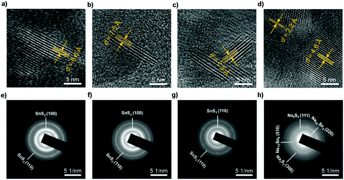 |
| | Fig. 15
Ex situ HRTEM and SAED patterns of SnS2 particles before sodiation and after discharging to different voltages, indicating the transformation from the SnS2 phase to Na2S2 and Na15Sn4 phases through conversion and alloy reactions. (a and e) Before sodiation. (b and f) After discharging to 1.72 V, where the Na ions diffuse along the ab-plane channels, resulting in a volume expansion along the c-axis direction. After subsequently discharging to (c and g) 1.69 V and (d and h) 0.01 V. Reproduced with permission.69 Copyright 2017, American Chemical Society. | |
3.2.2 Structurally designed SnS2 as the anode.
The large expansion of the pristine layered SnS2 during sodiation and the sluggish kinetics of the diffusion process hinder its further practical use in cost-effective NIBs. One attractive solution is through structural design of the electrode to endow the layered SnS2 with a more exposed surface or interface for shorter electron/Na-ion transfer pathways.211 For example, Zhou et al. fabricated a nanowall array structure via one-step pulsed spray evaporation chemical vapor deposition (PSE-CVD); the binder-free and carbon-free anodes showed a greatly improved reversible capacity and rate capability compared to those of particle layers.135 Liu et al. developed a general method to fabricate a series of SnS2 ultrathin nanosheets confined in different hollow carbon nanostructures (Fig. 16a–c), e.g., carbon nanotubes, nanoboxes, and nanospheres, for efficient capacitive sodium storage. SnS2/C nanohybrids formed by the multistep-template method have unique structural properties for Na-storage as manifested by the excellent specific capacity in the range of 525–631 mA h g−1 after 100 cycles without visible capacity decay at a current density of 200 mA g−1. The CE of the device approaches 100% in the cycling processes (Fig. 16d). It is noteworthy that the thin carbon shell effectively enhanced the electrical conductivity, prevented the aggregation and accommodated the volume change during cycling. Furthermore, through the reaction kinetics analysis it is revealed that a redox pseudocapacitive reaction mainly accounts for the high rate capabilities of the as-prepared nanohybrids, i.e., over 75% at a sweep rate of 1.0 mA s−1, due to the ultrathin SnS2 nanosheets with a large surface area.212
 |
| | Fig. 16 TEM images of the ultrathin SnS2 nanosheets confined in different hollow carbon structures including (a) nanotubes, (b) nanoboxes, and (c) hollow nanospheres. (d) Cycling performances and the corresponding coulombic efficiencies of the above-mentioned nanohybrids at 0.2 A g−1. Reproduced with permission.212 Copyright 2018, Elsevier. | |
3.2.3 SnS2/graphene composites as the anode.
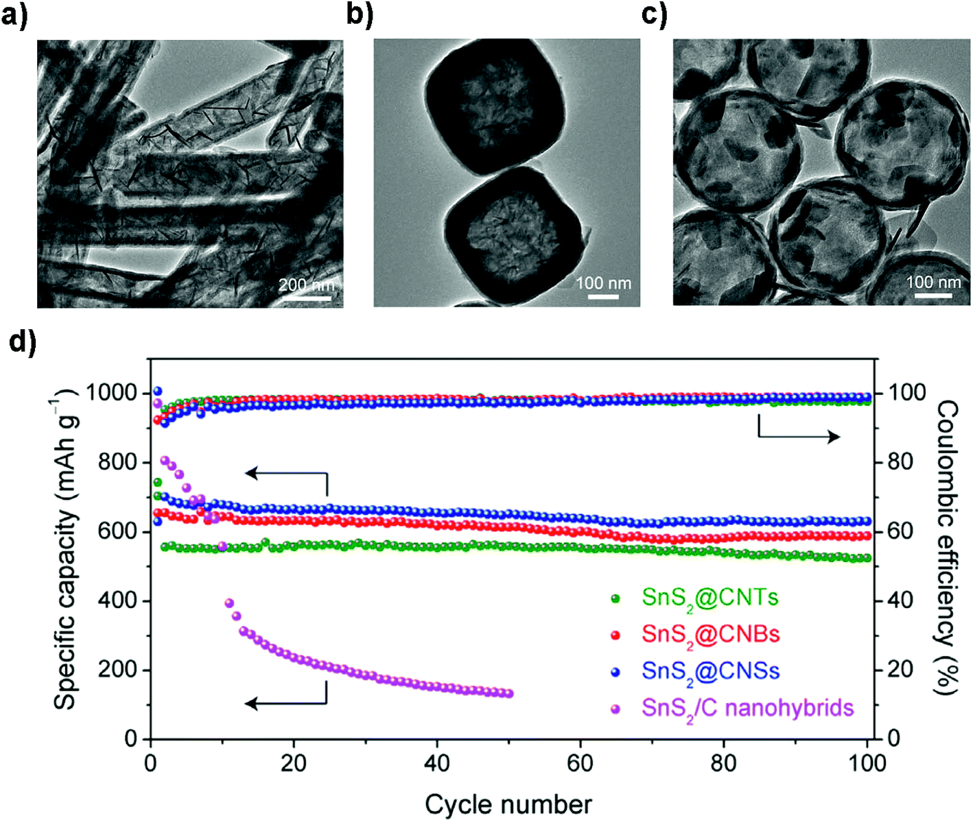
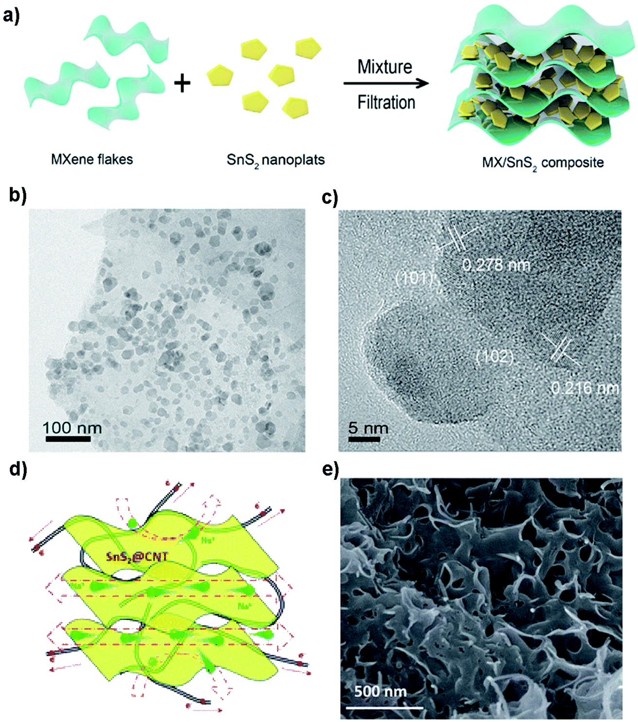
Incorporation of compatible graphene or rGO with layered SnS2 will alleviate the expansion of SnS2 during sodiation and enhance the electron/Na-ion conductivity of composite anodes, thus benefiting the capacity retention and rate performance.50,69,151,152,167,179,213–215 By combining with rGO, it has overcome the poor cycling stability of SnS2 in NIBs. The rGO/SnS2 composite shows a high capacity, high rate, and long cycle-life when used as an anode material for NIBs. For example, Liu et al. reported a hydrothermally obtained SnS2/rGO composite, showing a superior capacity of 650 mA h g−1 at 200 mA g−1 and a remarkable long-cycle capacity of ∼610 mA h g−1 (potential range 0.01–2.5 V) without obvious fading up to 300 cycles as well as a high rate capacity of 326 mA h g−1 at 4 A g−1. The impressive electrochemical performance can be attributed to the synergetic effects between the ultrafine SnS2 and the highly conductive graphene network.178 A layered SnS2/rGO composite synthesized by Qu et al. exhibited a high charge (desodiation) specific capacity of 630 mA h g−1 (at 0.2 A g−1) and a rate performance of 544 mA h g−1 (at 2 A g−1) with excellent capacity retention of 500 mA h g−1 at 1 A g−1 after a long cycle-life of 400 cycles. When paired up with a P2 phase Na0.80Li0.12Ni0.22Mn0.66O2 cathode (theoretical capacity of 118 mA h g−1) for a Na-ion full cell, it displayed relatively good stability with a capacity retention of 74% after 50 cycles in the voltage window of 1.0–4.2 V. The performance may be further improved by optimizing the anode-to-cathode mass ratio and the matching of the C-rates between the two electrode materials.213 And for a further in-depth study, Ma et al. reported a similar SnS2–rGO composite that delivered a reversible capacity of 630 mA h g−1 with negligible capacity loss and superb rate performance. This is attributed to a synergistic mechanism involving conversion and alloying reactions by synchrotron XRD and in situ X-ray absorption spectroscopy (XAS). Here, the rGO not only prevents active particle agglomeration but also coordinates with Na ions through electrostatic interactions. For example, the preferential c-axis orientation of SnS2 on conductive graphene exhibited a much higher capacity of 704 mA h g−1 (voltage range of 0.005–3.0 V vs. Li/Li+) after 100 cycles at a discharge current density of 50 mA g−1 as well as improved rate capability.216 Besides graphene, some alternative conductive substrates, frameworks or nanofillers can also enhance the conductivity and thus improve the electrochemical and/or mechanical performance of SnS2 composites.129,162–164 For example, Zhang's group reported a heterolayered SnS2/MXene (Fig. 17a–c) which showed an outstanding rate capacity and long-term cycling performance with low-temperature tolerance. This was ascribed to a synergistic enhancement effect between the metallic conductivity of MXenes and high redox activity of SnS2.163 A SnS2 nanosheet/CNTs composite prepared by Li et al. using a facile one-pot sintering route exhibited a high reversible capacity of 758 mA h g−1 at 100 mA g−1 and a competent cyclability with a retention of 87% over 300 cycles, as well as a good rate capacity of 445 mA h g−1 at 5 A g−1 (Fig. 17d and e).187
 |
| | Fig. 17 (a) Schematic illustration of the preparation and (b and c) TEM images of the SnS2/MXene composite by vacuum filtration. Reproduced with permission.163 Copyright 2018, Elsevier. (d) Schematic diagram and (e) SEM image of the layered SnS2@CNT nanocomposite with a porous structure and CNTs wrapped with layered SnS2 nanosheets for NIBs. Reproduced with permission.187 Copyright 2016, Royal Society of Chemistry. | |
The enhanced binding between the layered tin sulfide and conductive substrates via chemical modification or doping may improve the Li- and Na-ion battery performance.123,217,218 As demonstrated by both experimental results and computational calculations, the stronger affinity of tin sulfides to functionalized graphene or rGO provides a more robust composite architecture which can effectively and feasibly solve the long-term cycling issue for Li-ion and especially for Na-ion batteries.217 Zheng et al. exploited a facile and reliable commercial SnS2 dissolution–regeneration strategy, which is highlighted for its potential mass-production feature, to fabricate a flexible SnS2/S-doped rGO composite. The robust affinity between S-doped rGO sheets and SnS2 nanocrystals (ca. 25 nm; comprised of ultrafine NPs of ∼4 nm) without interstitial volume prevents the SnS2 particles from breaking away from the 2D substrates. The composite delivered a reversible capacity of 564 mA h g−1 at 0.1 A g−1 for NIBs.207 Jiang et al. reported the enhanced bonding of SnS2 ultrafine nanocrystals that were uniformly immobilized on amino-functionalized graphene. The tight contact between SnS2 NPs and the chemically modified conducting substrates benefited a composite material that maintained a high capacity of 680 mA h g−1 after 100 cycles at 200 mA h g−1 and an excellent long-cycle capacity of 480 mA h g−1 after 1000 cycles with a retention of 85% at 1 A g−1. The performance is much higher than that of SnS2 distributed on pristine graphene which showed a retention of merely 44%. The competent performance was due to the unique structure and the strong chemical bonding of active components at the functionalized conducting graphene interface.49
3.2.4 Free-standing anode.
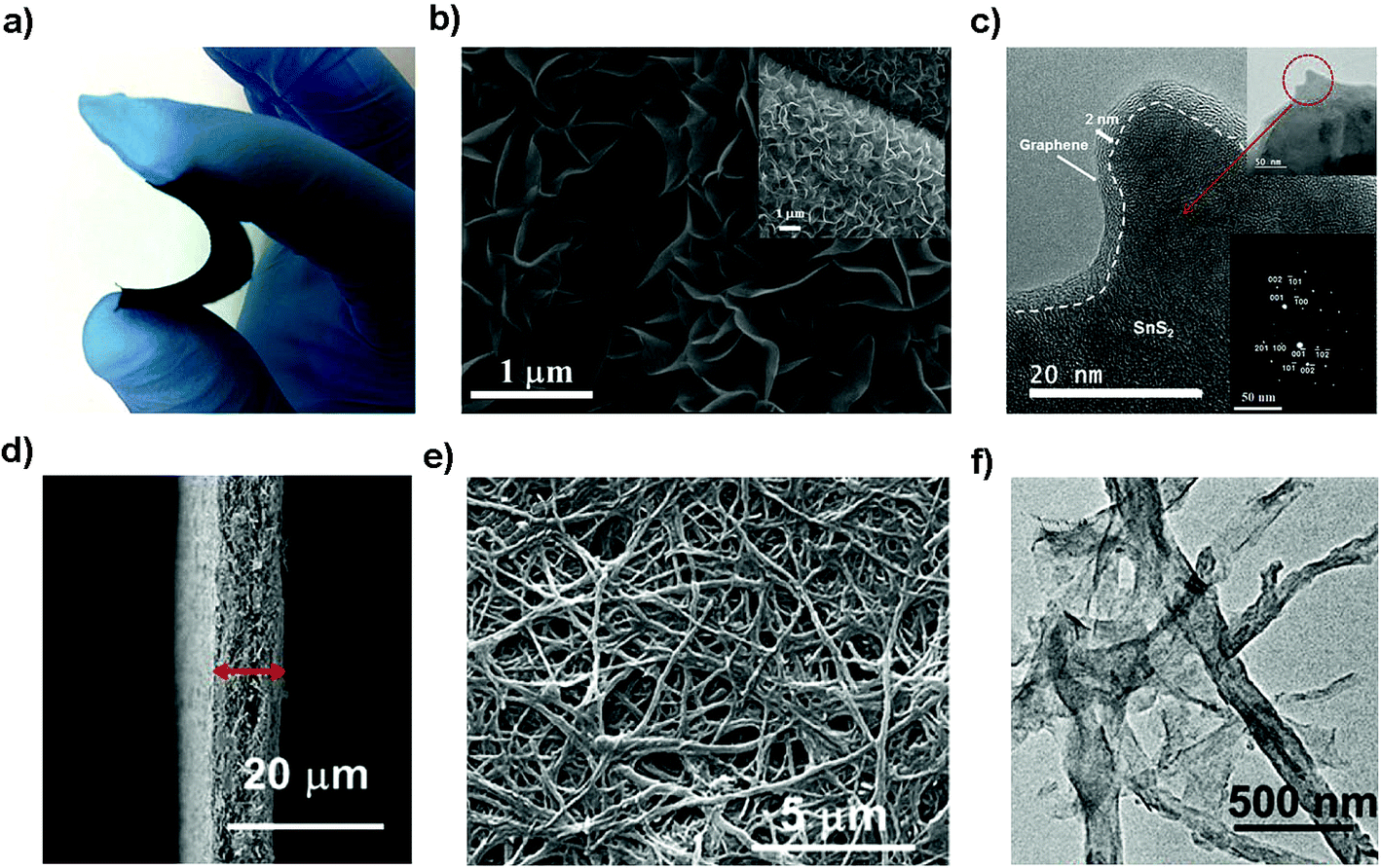
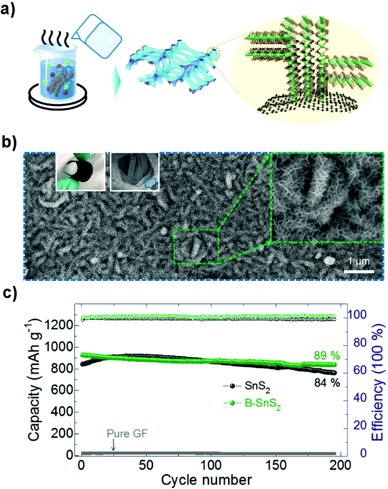
Flexible electrodes with light weight, low cost, high energy density and favorable mechanical properties have attracted intensive interest for next-generation wearable energy storage devices. The combination of layered tin sulfides with other conductive substrates such as woven or nonwoven substrates or frameworks has demonstrated to be promising suitable flexible electrodes for advanced wearable secondary batteries.219–222 Xu et al. prepared graphene coated SnS2 nanosheet arrays (10 nm in thickness and 1 μm in width) supported on carbon cloth as an integrated electrode without conductive additives, binders and metal current collectors (Fig. 18a–c), demonstrating a good cycling performance with a specific capacity of 378 mA h g−1 (potential range 0.01–1.0 V) at 1200 mA g−1 after 200 cycles and showing improved rate capacities as an advanced NIB anode. Compared with other related materials, the as-prepared integrated freestanding SnS2@graphene nanosheet arrays may show promise for high-energy and high-power flexible Na-ion batteries.208 A flexible paper-like free-standing ultrafine-SnS2-nanocrystals/graphene nanoribbon anode for high-performance NIBs was also prepared by unzipping CNTs, in situ reduction, self-assembly and sulfuration (Fig. 18d–f). The combination of ultrafine SnS2 crystals of 2.3 nm and the graphene nanoribbons showed a higher exposed surface and the strong capillary force during evaporation led to a compact paper (ρ = 0.94 g cm−3). The synergistic effects endowed the composite paper electrode with an excellent electrochemical performance, demonstrating a volumetric capacity of 508–244 mA h cm−3 in the current density range of 0.1–10 A g−1, and a long-term discharge capacity of 334 and 255 mA h cm−3 after 1500 cycles at 1 and 5 A g−1, respectively.223 The Shen group also designed a self-branched 2D layer SnS2 nanoarray on graphene foam through a facile controllable hot bath method, as shown in Fig. 19a and b. The as-designed flexible electrode exhibited a reversible areal capacity of ca. 900 mA h g−1 (∼3.7 mA h cm−2, Fig. 19c) and a high rate capacity of 400 mA h g−1 (1.6 mA h cm−2) at 10 A g−1 (40 mA cm−2). The fast kinetics of the alloy-based SnS2 electrode originated from the unsaturated edge effect which results in improved extrinsic pseudocapacitance.211,224 These fabrication strategies may pave the way for a new class of free-standing composite electrodes used for energy storage and conversion.
 |
| | Fig. 18 (a–c) Photo, SEM and TEM (inset SAED pattern) images of the flexible and binder-free integrated NIB anode of SnS2@graphene nanosheet arrays with carbon cloth as a 3D conductive network via a facile two-step solvothermal route. Reproduced with permission.208 Copyright 2016, Elsevier. (d–f) SEM and TEM images of the flexible paper-like free-standing electrode by anchoring ultrafine SnS2 nanocrystals on graphene nanoribbons via unzipping CNTs and the self-assembly process for high-performance NIBs. Reproduced with permission.223 Copyright 2017, American Chemical Society. | |
 |
| | Fig. 19 (a) Schematic illustration of the fabrication of self-branched 2D SnS2 (B–SnS2) nanoarrays on graphene foam (GF), (b) SEM images of the typical GF-supported B–SnS2 electrode structures. Left inset is a digital photo and middle insets are the low- and high-magnification SEM images, respectively. (c) Cycling performance and coulombic efficiency of the as-prepared B–SnS2 compared to SnS2 without branches and pure GF at 200 mA g−1. Reproduced with permission.224 Copyright 2016, American Chemical Society. | |
4. SnSe
Binary laminar semiconductive IV–VI compounds SnSe (orthorhombic) and SnSe2 (hexagonal), both with a typical layered crystal structure and narrow band gap, are a new class of layered TMC materials for alkali-ion batteries due to their higher electrical conductivity than other TMCs such as SnO2 and SnSx.48,61,225
4.1 SnSe for Li-ion batteries
4.1.1 Lithium storage mechanism studies in SnSe.
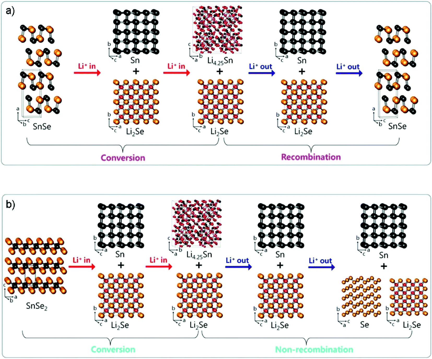
By investigating the phase change mechanism of tin selenides by ex situ X-ray diffraction (XRD) and Se K-edge EXAFS analyses, Lee and Park argued that layered SnSe and SnSe2 undergo different crystallographic phase change reaction mechanisms during the lithiation/delithiation process (Fig. 20a and b), i.e., the Li2Se formed by SnSe2 is partially irreversible and no recombination occurs during delithiation compared to the high reversibility of the SnSe.61 When the two layered compounds were tested for use as anodes of LIBs, it was further confirmed that SnSe (first lithiation/delithiation capacity: 897/803 mA h g−1 at 100 mA g−1 with an ICE of 89.5%) shows better electrochemical reversibility of Li insertion/extraction than SnSe2 (850/557 mA h g−1 at 100 mA g−1, ICE 65.5%), e.g., the SnSe/C electrode fabricated by high-energy ball milling of SnSe and Super P carbon black delivered a superior long-cycle capacity of 626 mA h g−1 after 200 cycles at 100 mA g−1, and a high rate capacity of 580 mA h g−1 at 1460 mA g−1 between 0.0 and 2.5 V (vs. Li+/Li). A similar claim on the reversible conversion mechanism of SnSe has also been confirmed by the Fu group that the reversible formation and decomposition reaction of Li2Se is utterly different from those of SnO2 or SnO and even SnS2.226 Thus, it enables the SnSe anode to be on a par with its oxide and sulfide analogues in terms of reversible capacity and be a promising alternative for high energy-density LIBs.
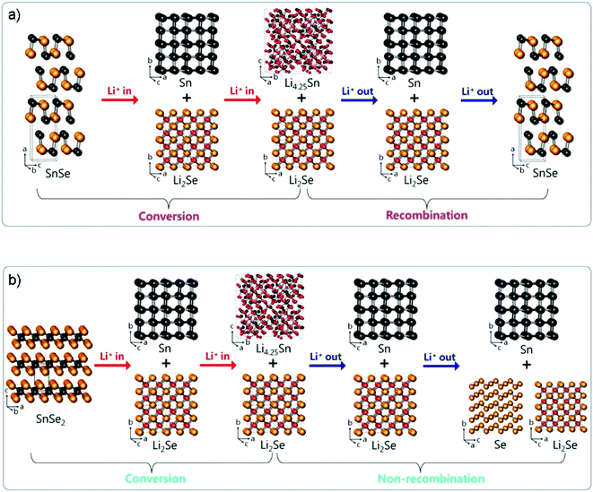 |
| | Fig. 20 Crystallographic phase change reaction mechanism of layered SnSe and SnSe2 during lithiation/delithiation. (a) Conversion/recombination mechanism of puckered-layer-structured SnSe. (b) Conversion/nonrecombination mechanism of three-layer-packaged layer-structured SnSe2. Reproduced with permission.61 Copyright 2017, American Chemical Society. | |
4.1.2 SnSe anode.
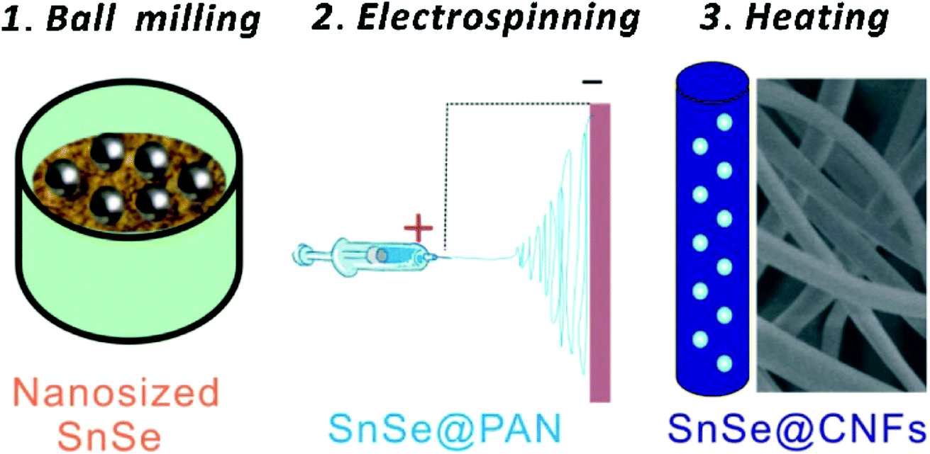
As an earth-abundant, environmentally friendly and chemically stable material, SnSe exhibits a high theoretical capacity of 847 (based on the formation of Li4.25Sn and Li2Se) and outstanding volumetric capacity, showing extraordinary advantages as a promising candidate anode for advanced LIBs. However, it may also undergo large volume change and particle aggregation during the charge/discharge process and poor electrochemical stability thereof.61,64,225,227 To address these issues, some efforts have been made including structural optimization,225,228,229 incorporation of conductive and buffering matrices,230,231 and electrode design.232 For example, the Guo group exploited a new colloid chemistry strategy for the synthesis of 2D ultrathin layered SnSe nanoplates, which stack or assemble via weak van der Waals forces and can facilitate ion transfer and accommodate volume expansion.225 The SnSe nanoplates exhibited a high reversible capacity of 788 mA h g−1 at 200 mA g−1 over 300 cycles, and excellent and stable rate capabilities of 714, 570, and 471 mA h g−1 at 0.5, 2.0, and 5.0 A g−1. Zhang et al. prepared a SnSe/C nanocomposite with a SnSe alloy (size 50–80 nm) homogeneously distributed within an amorphous carbon matrix by high energy ball milling of Sn, Se and carbon black powders.64 The SnSe/C nanocomposite showed enhanced electrochemical performances, e.g., a high reversible capacity of 633 mA h g−1 after 100 cycles at 500 mA g−1, and a high rate capability of 669 and 598 mA h g−1 at 1.0 and 2.0 A g−1, respectively. Moreover, with the ball-milled SnSe nanoparticles embedded in electrospun carbon nanofibers (CNFs), the SnSe@CNFs nanocomposite prepared by Zhang and coworkers (Fig. 21) showed a larger and ultrastable capacity of 840 mA h g−1 (potential window 0.01–2.5 V) over 100 cycles at 200 mA g−1 as well as competitive rate capability.230 Amongst these highly conductive carbonaceous matrices, graphene has been a popular choice and it is important to highlight that the particle size and dispersion on graphene will greatly influence its effectiveness as an anode material.62,233,234 For example, Qian and coworkers developed a graphene oxide-wrapped SnSe rod-like nanocrystal composite (GO@NCs) with the assistance of chitosan, which showed an enhanced reversible capacity of 764 mA h g−1 after 100 cycles at 100 mA g−1 as well as rate capabilities of 861 and 691 mA h g−1 at 500 and 1000 mA g−1, which are much higher than those of bare SnSe nanorods.234
 |
| | Fig. 21 Schematic illustration of the synthesis process of SnSe/C hybrid nanofibers. Reproduced with permission.230 Copyright 2016, Elsevier. | |
4.1.3 Free-standing anode.
For flexible energy storage/conversion devices, Wang et al. designed a binder-free integrated SnSe anode for LIBs via a simple spray-painting of SnSe nanocrystal-based ink onto conductive carbon fabric.232 The 3D flexible electrode herein demonstrated an excellent capacity of 676 mA h g−1 at 200 mA g−1 over 80 cycles and an enhanced rate capability due to the improved ion transportation from the electrolyte to active materials and the efficient charge transfer between the current collector and the active materials. The spray-painted route may allow for many potential applications in facile, cost-effective, and flexible and high-performance energy-storage devices. In addition, SnSe may also be incorporated into traditional SnOx/C composites to improve the electrical conductivity of the resulting irreversible Li2O which inhibits the full use of their Li storage performance. As an example, the optimal SnSe/SnOx@CNFs as a free-standing and binder-free anode can exhibit a higher ICE of 86.5%, better reversible capacity (741 mA h g−1 at 200 mA g−1 after 70 cycles), and robust long-term stability up to 1000 cycles, compared to that of pristine SnOx@CNFs (ICE 68.1%, 552 mA h g−1 at 200 mA g−1 after 70 cycles) and commercial graphite.235
4.1.4 Ternary tin chalcogenide anode.
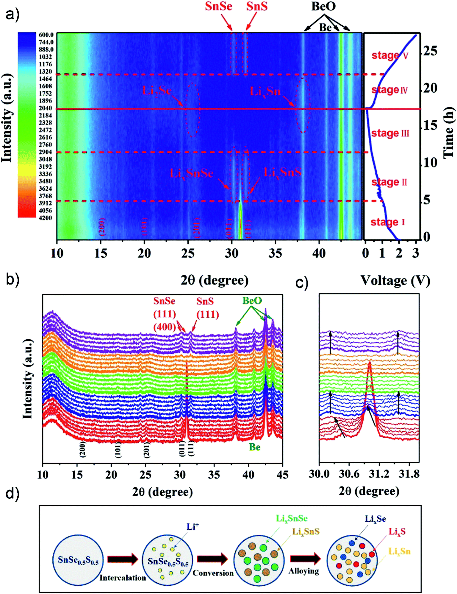
Ternary tin chalcogenides have been relatively rarely reported as an anode active material, although the synergism of Se and S elements may provide a larger layer space (or grain boundaries), better electronic/ionic conductivity, and improved properties thereof making it a promising candidate for high-performance anode materials.85,236 Tang el al. developed a unique SnSe0.5S0.5 nanoplate via a polyol-method followed by calcination.236 The compound as a LIB anode exhibited an excellent discharge specific capacity of 1144 mA h g−1 after 100 cycles at 100 mA g−1, and 681 mA h g−1 after 200 cycles at 500 mA g−1, and delivered a high rate capacity of 473 mA h g−1 at 5 A g−1. To further investigate the electrochemical mechanisms upon lithiation/delithiation processes, in situ XRD analysis was applied in the first cycle (Fig. 22). The 2D contour plots (Fig. 22a) and line plots (Fig. 22b and c) revealed a structural evolution/reaction mechanism of SnSe0.5S0.5 from lattice expansion (i.e. intercalation), a conversion reaction (forming crystalline phases of LixSnSe and LixSnS), to an alloying reaction (by forming low crystallinity LixSe, LixSn and amorphous LixS) in different stages, which confirmed the specific Li-ion storage mechanism for ternary tin chalcogenides (summarized in Fig. 22d). When explored as an anode in a full cell with Li(Ni0.6Co0.2Mn0.2)O2 as the cathode, it can deliver a high capacity of 535 mA h g−1 after 50 cycles with a cut-off voltage ranging from 4.5 to 1.5 V. Furthermore, they developed a SnSe0.5S0.5/C nanocomposite by incorporation with a glucose-derived carbon.227 When used as an anode material for LIBs, it exhibited a high specific capacity of 989 mA h g−1 at 100 mA g−1, and an enhanced long-term cycling stability, e.g., 625 mA h g−1 after 1000 cycles at a current density of 500 mA g−1. And it also delivered an excellent rate capability of 646, 553, and 389 mA h g−1 at 1, 2, and 5 A g−1, respectively. The impressive electrochemical performance is mainly attributed to the enhanced reaction kinetics due to the extrinsic pseudocapacitive contribution.
 |
| | Fig. 22
In situ XRD analysis of SnSe0.5S0.5 during the first charging and discharging process: (a) 2D contour plots of in situ XRD patterns and the corresponding discharge/charge profiles, (b) line plot of in situ XRD patterns, and (c) selected 2θ region plot. (d) The schematic illustration of the electrochemical process of the SnSe0.5S0.5 anode. Reproduced with permission.236 Copyright 2018, Elsevier. | |
4.2 SnSe for Na-ion batteries
4.2.1 Structurally designed SnSe as the anode.
Due to the high theoretical capacity (780 mA h g−1) and abundant resources as well as enhanced conductivity and a low potential plateau, SnSe could be a promising anode material for increasingly important high power/energy density NIBs.65,225,237 Similar to other Sn-based materials, SnSe also suffers from some major problems including a large volume change during the charge/discharge process; some solutions are provided to further enhance the conductivity, shorten the electron/ion transfer pathway as well as maintain the electrode stability.238 For example, the Kang group prepared a kind of thin and uniform SnSe nanoplate with a high aspect ratio (11.3) via one-pot spray pyrolysis, where the SnO2/SeO2 composite was first reduced to a molten Sn–Se mixture and then exothermally grown to form SnSe nanocrystals with excess metalloid Se eliminated by forming H2Se gas.239 The as-prepared aggregation-free SnSe nanoplates showed superior Na-ion storage properties, delivering a high capacity of up to 558 mA h g−1 after 50 cycles at 300 mA g−1, and a good rate capability of 443 mA h g−1 at 1.0 A g−1. And the ladder-like cluster of SnSe nanoplates as a dual anode material reported by the Guo group when used as an NIB anode can deliver a high reversible capacity of 393 mA h−1 after 300 cycles at 50 mA g−1, and outstanding and stable rate capabilities of 386, 356 and 340 mA h g−1 at 0.2, 1, and 2 A g−1.225 It is noteworthy that the ultrathin SnSe showed a flat and low voltage plateau (∼0.2 V) for NIBs, which is quite beneficial for the further practical application in full cells and batteries. Yuan et al. developed a surfactant-free aqueous synthesis of single-crystalline SnSe nanosheet clusters (SnSe NSCs) using an environmentally friendly and low-cost process, which show high energy- and power-density features as an anode for NIBs.237 The as-synthesized SnSe NSCs demonstrated superior electrochemical performances with a reversible capacity of 738 mA h g−1 at 25 mA g−1 (730 mA h g−1 after 30 cycles), and excellent rate capability of up to 40 A g−1 (e.g., 200 and 106 mA h g−1 at 10 and 20 A g−1, respectively; much higher than those of SnSe particles and some carbonaceous materials), and a high energy density of up to 141 W h kg−1 in a full cell (Na0.67Ni0.41Mn0.72O2 cathode) of a high average discharge voltage platform of ∼3.4 V. One of the distinguished features beyond the usual ones is the mechanical stability of the interconnected SnSe NSCs compared to isolated thin nanosheets. It shows great promise for the high-performance advanced electrode for next-generation NIBs.
4.2.2 SnSe/C composites as the anode.
To further enhance the electrical conductivity and accommodate the volume change during the chare/discharge process, Kim et al. prepared a SnSe alloy by a facile ball milling of the tin selenide and Super P carbon under an Ar atmosphere.65 The obtained SnSe/C composite when examined as an anode material for NIBs showed a high reversible capacity of 707 mA h g−1 at 143 mA g−1 (∼0.2C) in the potential window of 0.0–2.0 V with negligible capacity fading over 50 cycles, delivering 91% of the theoretical capacity of SnSe, and it also showed a rate capacity of ca. 350 mA h g−1 at 1C. Through studying the reversible sodiation/desodiation mechanism using ex situ XRD and TEM with EDS analysis, it is claimed that the improved cycling performance of SnSe/C was mainly attributed to the confinement effect of amorphous NaxSn nanodomains in the crystalline Na2Se matrix during cycling, i.e., in the case of SnSe, the Sn or NaxSn domains were embedded in the Na2Se matrix during cycling and thus agglomeration of Sn is suppressed, leading to enhanced cycling performance. Another SnSe/C nanocomposite reported by Zhang et al. exhibited an enhanced long-term capacity of 325 mA h g−1 (voltage window of 0.01–2.0 V) after 200 cycles at a current density of 500 mA g−1 with 72.5% retention of the 2nd cycle capacity, and a high rate capability of 343 and 323 mA h g−1 at 1.0 and 2.0 A g−1, respectively.64 Yang et al. prepared a SnSe/rGO nanocomposite with SnSe nanoparticles confined in the graphene matrix by a facile ball-milling method.240 The redox behavior of SnSe remains almost unchanged upon the incorporation of rGO, although the nanocomposite showed significantly enhanced electrochemical performance with a high specific reversible capacity of 570 mA h g−1 after 50 cycles at 100 mA g−1, and 385 mA h g−1 after 115 cycles at 1.0 A g−1 (capacity retention of 98%), as well as an outstanding rate capability of 260 mA h g−1 at 10 A g−1. The improvement can be ascribed to the high electronic conductivity of rGO, which further buffers the volume change and maintains the mechanical integrity of the electrode during the sodiation/desodiation process. And it is suggested that the improved electrochemical properties might be anticipated if one component is subjected to the (de)sodiation process while the other acted as a buffer to alleviate the volume change, since Na3.75Sn and Na2Se have different (de)sodiation or (de)alloying potentials. In addition, when the abovementioned ternary SnSe0.5S0.5/C nanocomposite for LIBs was used as a NIB anode material, it exhibited a high specific capacity of 683, 549, and 506 mA h g−1 at 100, 500, and 1000 mA g−1, respectively, and a long-cycle capacity of 430 mA h g−1 after 100 cycles at 200 mA g−1 with a coulombic efficiency (CE) close to 100%.227
5. SnSe2
SnSe2 is a 2D transition metal chalcogenide material with a CdI2-type hexagonal layered structure (a = b = 3.81 Å and c = 6.14 Å), i.e., one layer of Sn atoms and two layers of Se atoms are periodically stacked for a closely packed but weakly interacting sandwich structure, showing many emerging applications including photodetectors and optoelectronic and energy storage.59,66
5.1 SnSe2 for Li-ion batteries
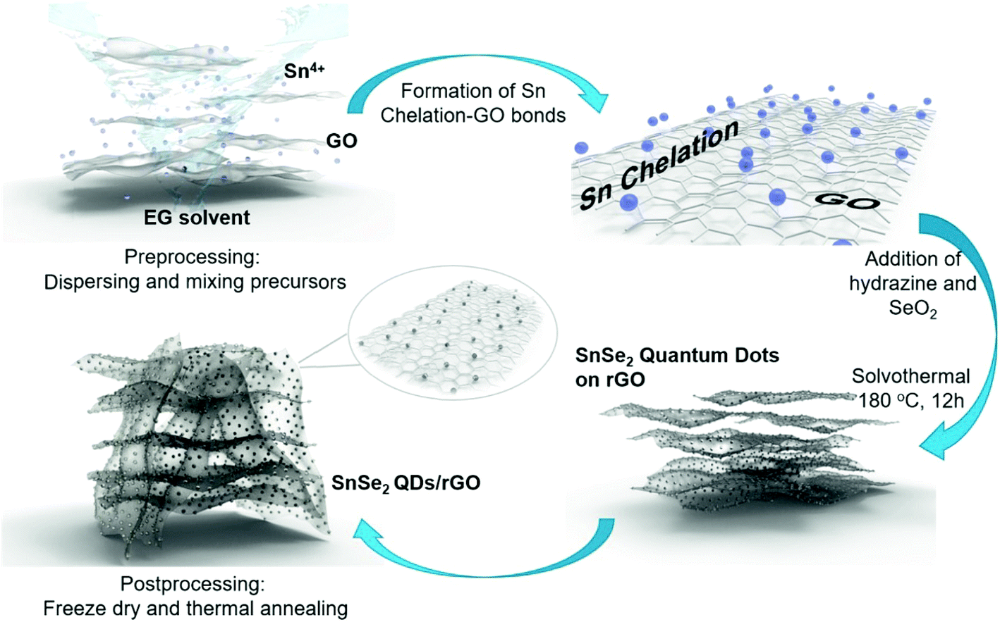
SnSe2, as a promising anode for advanced LIBs, can deliver a high theoretical capacity of 813 mA h g−1 (426 mA h g−1 based on the alloying reaction and 387 mA h g−1 based on the conversion reaction),59,62 despite some literature debate on the theoretical maximum reversible storage capacity of 426 mA h g−1 in view of the inactive Li2Se that is irreversibly formed.66 The design and synthesis of SnSe2 nanostructures for energy storage and conversion has recently emerged. Im et al. exploited a gas-phase laser photolysis reaction route for the synthesis of tin selenide nanocrystals; SnSe2 can deliver a stable reversible capacity of 412 mA h g−1 after 70 cycles at ∼100 mA g−1, and higher rate capability than its analogues such as GeSex, due to the smallest volume expansion in the cubic Sn (α-Sn) phase which could guarantee improved cycling capability of Sn compounds.60 And the synthesis route can be extended to other TMCs for high-capacity LIBs. Choi et al. prepared a SnSe2 nanoplate/rGO composite via a solution approach and applied it as an anode material for LIBs, which showed a promising storage performance (with a high capacity of up to 640 mA h g−1 after 30 cycles at 40 mA g−1) and rate capability superior to those of pure SnSe2 nanoplates (260 mA h g−1) or graphene alone.66 Further control of the size of SnSe2 and enhancing the activity of Li2Se, which forms during initial lithiation and is usually considered irreversible, will improve the capacity and stability of the SnSe2 anode; herein, the Yang group designed ultra-fine SnSe2 quantum dots (QDs, 5 ± 2 nm) embedded in a 3D rGO matrix (Fig. 23), where the released Sn nanoparticles are able to catalyze the decomposition of Li2Se and drive the conversion of Sn to SnSe2.62 In this manner, both the conversion and alloying reactions can be fully utilized and greatly increase the reversible capacity of the SnSe2 anode. The as-prepared SnSe2 QDs/rGO nanocomposite exhibited an enhanced reversible capacity of 746 mA h g−1 at 200 mA g−1 over 500 cycles close to the theoretical value, and showed a high rate capability of 325 mA h g−1 up to 5.0 A g−1 as well as an ultralong cycle life with 92.2% capacity retention (i.e., 410 mA h g−1) after 3000 cycles at 2.0 A g−1. Further insight into the reaction mechanism and the successful utilization of both conversion and alloying reactions in SnSe2 enable it to be more competitive to its analogues and have promising potential for use in advanced LIBs.
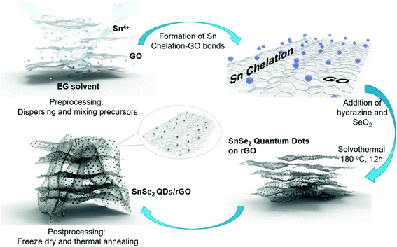 |
| | Fig. 23 Schematic illustration of the synthesis process of SnSe2 quantum dots (QDs) on reduced graphene oxide (rGO) nanosheets. Reproduced with permission.62 Copyright 2018, Elsevier. | |
5.2 SnSe2 for Na-ion batteries
Layered SnSe2 can deliver a high theoretical capacity of 756 mA h g−1 (based on 7.75 mol Na stored in 1 mol SnSe2) as an anode material for NIBs.59 The large interlayer spacing will be beneficial for more Na-ion intercalation and the buffering of large volume change. Alshareef and coworkers prepared a SnSe2 nanosheets/rGO nanocomposite using a safe and stable selenium source (i.e., N2 saturated NaHSe solution), which exhibited a high reversible capacity of 515 mA h g−1 (voltage window of 0.005–2.5 V) after 100 cycles at 100 mA g−1, and excellent rate capabilities (398 and 365 mA h g−1 at 1.0 and 2.0 A g−1, respectively), better than those of the pure SnSe2 electrode.59 Further HRTEM and ex situ XRD analyses revealed the specific electrochemical mechanism and reversible structure conversions upon the sodiation/desodiation processes (Fig. 24a), i.e., during the sodiation (discharge) process, the intercalation of Na+ into SnSe2 is followed by formation of β-Sn and Na2Se via a conversion reaction, and then an alloying reaction gradually occurs to form small crystallites of the NaxSn (x = 3.75) alloy; and during the desodiation (charge) process, the NaxSn phase reversely transforms into β-Sn and the nanosized/polycrystalline SnSe2 is finally formed, indicating a high electrochemical reaction reversibility (Fig. 24b). The enhanced performances could be attributed to the synergistic effect that combines the advantages of 2D SnSe2 nanosheets and the formation of the 3D conductive network by graphene, which will not only further enhance the conductivity but also support an ideal matrix for the transportation and storage of Na ions due to its high intrinsic surface area and flexibility as well as the buffering of volume change and preventing particle aggregation during the (de)sodiation process.
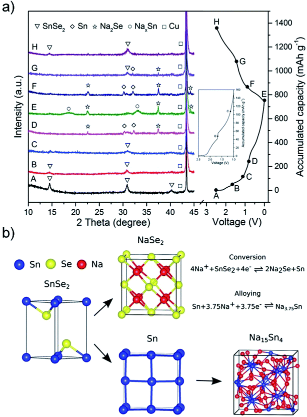 |
| | Fig. 24 (a) Ex situ XRD patterns of the SnSe2/rGO electrode collected at different discharge/charge states as indicated in the corresponding voltage profile (A: fresh; B–E: discharge to 1.70, 1.20, 0.78, and 0.005 V; F–H: charge to 1.05, 1.42, and 2.50 V). (b) Schematic illustration of the structural evolution during the sodiation process. Reproduced with permission.59 Copyright 2016, Wiley-VCH. | |
6. Conclusions and prospectives
In this review, we have summarized the recent research progress in tin sulfides and selenides (SnS, SnS2, SnSe, and SnSe2) as promising anode materials for LIBs and NIBs. Although great achievements have been made via the rational and creative design of electrode material structures to overcome their drawbacks, the strategies that have demonstrated effectiveness to achieve the potential of tin sulfide and selenide based anode materials for LIBs and NIBs can be summarized as follows: (i) the matching of kinetics, mass ratio, conductivity, etc. between the anode and cathode materials is also vital for high-capacity, high-rate, and long-life full cells with optimized performance. (ii) The more exposed surface or interface of the electrode material is in favor of higher capacity and rate performance. (iii) high-temperature annealing treatment of the composites formed by tin sulfide and carbon materials will increase the material conductivity and lower the average potential, thus benefiting the performance of full-cells with higher voltage and higher energy density. However, the structure or chemical composition may change during the annealing process, and therefore a balanced consideration or optimization is needed. (iv) The detailed mechanisms of electrochemical processes and intermediates need to be further studied for the higher reversible conversion of active materials. (v) The mechanism of capacitive or diffusion-dominated Li or Na ion storage, or of a synergistic storage method for LIBs or NIBs should be further investigated for batteries optimized with much higher power density as well as favorable energy density. (vi) The p–n heterojunction structures or nanocoating with other conductive or protective layers will improve the high rate capability and long-term cycling stability. (vii) Preoccupation of the defects/edges or pre-lithiation/sodiation of the irreversible parts of the composite anode materials as well as the adoption of optimized electrolytes can be a facile approach to increase the initial CE and the whole energy density of the full cells or batteries thereof.
Conflicts of interest
There are no conflicts to declare.
Abbreviations
| LIBs | Lithium-ion batteries |
| NIBs | Sodium-ion batteries |
| TMCs | Transition-metal chalcogenides |
| 3D | Three-dimensional |
| 2D | Two-dimensional |
| 1D | One-dimensional |
| CE | Coulombic efficiency |
| ICE | Initial coulombic efficiency |
| ESD | Electrostatic spray deposition |
| PPy | Polypyrrole |
| PANi | Polyaniline |
| VN | Vanadium nitride |
| NB | Nanobelt |
| SG | Spherical graphene or S-doped graphene |
| rGO | Reduced graphene oxide |
| PVP | Polyvinyl pyrrolidone |
| NPs | Nanoparticles |
| MWCNTs | Multi-walled carbon nanotubes |
| CNTs | Carbon nanotubes |
| DEGDME | Diethylene glycol dimethyl ether |
| EC/DEC | Ethylene carbonate/diethyl carbonate |
| PAA-CMC | Poly(acrylic acid)/sodium carboxymethyl cellulose |
| PDDA | Polydiallyldimethylammonium chloride |
| HRTEM | High-resolution transmission electron microscopy |
| SAED | Selected area electron diffraction |
| XAS | X-ray absorption spectroscopy |
| XRD | X-ray powder diffraction |
| EDS | Energy dispersive X-ray spectroscopy |
| EXAFS | Extended X-ray absorption fine structure |
Acknowledgements
This work was supported by the National Natural Science Foundation of China (grant no. 51302079), the National Natural Science Foundation of Hunan Province (grant no. 2017JJ1008), and the 111 project (grant no. B12015). H. X. W acknowledges the financial support of Queensland University of Technology through the Strategic Fund.
References
- J. Xu, J. Ma, Q. Fan, S. Guo and S. Dou, Adv. Mater., 2017, 29, 1606454 CrossRef PubMed.
- J. Xu, Y. Dou, Z. Wei, J. Ma, Y. Deng, Y. Li, H. Liu and S. Dou, Adv. Sci., 2017, 4, 1700146 CrossRef PubMed.
- Y. Tu, D. Deng and X. Bao, J. Energy Chem., 2016, 25, 957–966 CrossRef.
- C. Zhang, C. Lu, F. Zhang, F. Qiu, X. Zhuang and X. Feng, J. Energy Chem., 2018, 27, 86–98 CrossRef.
- Z. Su, Z. Wei, C. Lai, H. Deng, Z. Liu and J. Ma, Energy Storage Mater., 2018, 14, 129–135 CrossRef.
- C. Cui, Z. Wei, J. Xu, Y. Zhang, S. Liu, H. Liu, M. Mao, S. Wang, J. Ma and S. Dou, Energy Storage Mater., 2018, 15, 22–30 CrossRef.
- C. Yuan, H. B. Wu, Y. Xie and X. W. D. Lou, Angew. Chem., Int. Ed., 2014, 53, 1488–1504 CrossRef PubMed.
- L. Yu, H. B. Wu and X. W. D. Lou, Acc. Chem. Res., 2017, 50, 293–301 CrossRef PubMed.
- W. Luo, F. Shen, C. Bommier, H. Zhu, X. Ji and L. Hu, Acc. Chem. Res., 2016, 49, 231–240 CrossRef PubMed.
- Y. Q. Luo, Y. J. Tang, S. S. Zheng, Y. Yan, H. Q. Xue and H. Pang, J. Mater. Chem. A, 2018, 6, 4236–4259 RSC.
- H. Xu, L. Ma and Z. Jin, J. Energy Chem., 2018, 27, 146–160 CrossRef.
- M. Mao, C. Cui, M. Wu, M. Zhang, T. Gao, X. Fan, J. Chen, T. Wang, J. Ma and C. Wang, Nano Energy, 2018, 45, 346–352 CrossRef.
- X. Deng, Z. Wei, C. Cui, Q. Liu, C. Wang and J. Ma, J. Mater. Chem. A, 2018, 6, 4013–4022 RSC.
- Q. Wang, J. Xu, W. Zhang, M. Mao, Z. Wei, L. Wang, C. Cui, Y. Zhu and J. Ma, J. Mater. Chem. A, 2018, 6, 8815–8838 RSC.
-
C. Mi and M. A. Masrur, Hybrid electric vehicles: principles and applications with practical perspectives, John Wiley & Sons, 2017 Search PubMed.
- H. Hao, X. Cheng, Z. Liu and F. Zhao, Transport. Res. D, 2017, 56, 68–84 CrossRef.
- J. W. Choi and D. Aurbach, Nat. Rev. Mater., 2016, 1, 16013 CrossRef.
- S. Y. Hong, Y. Kim, Y. Park, A. Choi, N.-S. Choi and K. T. Lee, Energy Environ. Sci., 2013, 6, 2067–2081 RSC.
- H. Kang, Y. Liu, K. Cao, Y. Zhao, L. Jiao, Y. Wang and H. Yuan, J. Mater. Chem. A, 2015, 3, 17899–17913 RSC.
- M. Á. Muñoz-Márquez, D. Saurel, J. L. Gómez-Cámer, M. Casas-Cabanas, E. Castillo-Martínez and T. Rojo, Adv. Energy Mater., 2017, 7, 1700463 CrossRef.
- Y. Kim, K.-H. Ha, S. M. Oh and K. T. Lee, Chem.–Eur. J., 2014, 20, 11980–11992 CrossRef PubMed.
- C. Yang, X. Zhong, Y. Jiang and Y. Yu, Chin. Chem. Lett., 2017, 28, 2231–2234 CrossRef.
- K. Chen, Q. Wang, Z. Niu and J. Chen, J. Energy Chem., 2018, 27, 12–24 CrossRef.
- J. Lu, Z. Chen, Z. Ma, F. Pan, L. A. Curtiss and K. Amine, Nat. Nanotechnol., 2016, 11, 1031–1038 CrossRef PubMed.
- Y. Li, Y. Lu, C. Zhao, Y.-S. Hu, M.-M. Titirici, H. Li, X. Huang and L. Chen, Energy Storage Mater., 2017, 7, 130–151 CrossRef.
- J. Lang, L. Qi, Y. Luo and H. Wu, Energy Storage Mater., 2017, 7, 115–129 CrossRef.
- Y. Liu, N. Zhang, X. Liu, C. Chen, L.-Z. Fan and L. Jiao, Energy Storage Mater., 2017, 9, 170–178 CrossRef.
- C. Tan, X. Cao, X.-J. Wu, Q. He, J. Yang, X. Zhang, J. Chen, W. Zhao, S. Han, G.-H. Nam, M. Sindoro and H. Zhang, Chem. Rev., 2017, 117, 6225–6331 CrossRef PubMed.
- M. Xu, T. Liang, M. Shi and H. Chen, Chem. Rev., 2013, 113, 3766–3798 CrossRef PubMed.
- T. Niu and A. Li, Prog. Surf. Sci., 2015, 90, 21–45 CrossRef.
- Q. Yun, Q. Lu, X. Zhang, C. Tan and H. Zhang, Angew. Chem., Int. Ed., 2018, 57, 626–646 CrossRef PubMed.
- V. Nicolosi, M. Chhowalla, M. G. Kanatzidis, M. S. Strano and J. N. Coleman, Science, 2013, 340, 1226419 CrossRef.
- D. Chen, W. Chen, L. Ma, G. Ji, K. Chang and J. Y. Lee, Mater. Today, 2014, 17, 184–193 CrossRef.
- D. L. Duong, S. J. Yun and Y. H. Lee, ACS Nano, 2017, 11, 11803–11830 CrossRef PubMed.
- X. Zhang, L. Hou, A. Ciesielski and P. Samorì, Adv. Energy Mater., 2016, 6, 1600671 CrossRef.
- X. Wang, Q. Weng, Y. Yang, Y. Bando and D. Golberg, Chem. Soc. Rev., 2016, 45, 4042–4073 RSC.
- L. Peng, Y. Zhu, D. Chen, R. S. Ruoff and G. Yu, Adv. Energy Mater., 2016, 6, 1600025 CrossRef.
- H. Wang, H. Yuan, S. Sae Hong, Y. Li and Y. Cui, Chem. Soc. Rev., 2015, 44, 2664–2680 RSC.
- J. Azadmanjiri, V. K. Srivastava, P. Kumar, M. Nikzad, J. Wang and A. Yu, J. Mater. Chem. A, 2018, 6, 702–734 RSC.
- X. Xu, W. Liu, Y. Kim and J. Cho, Nano Today, 2014, 9, 604–630 CrossRef.
- Y. Xiao, S. H. Lee and Y.-K. Sun, Adv. Energy Mater., 2017, 7, 1601329 CrossRef.
- D. Chao, C. Zhu, P. Yang, X. Xia, J. Liu, J. Wang, X. Fan, S. V. Savilov, J. Lin, H. J. Fan and Z. X. Shen, Nat. Commun., 2016, 7, 12122 CrossRef PubMed.
- L. Wu, H. Lu, L. Xiao, J. Qian, X. Ai, H. Yang and Y. Cao, J. Mater. Chem. A, 2014, 2, 16424–16428 RSC.
- X.-Y. Yu, L. Yu and X. W. Lou, Adv. Energy Mater., 2016, 6, 1501333 CrossRef.
- W. Kang, Y. Wang and J. Xu, J. Mater. Chem. A, 2017, 5, 7667–7690 RSC.
- W. Ni, B. Wang, J. Cheng, X. Li, Q. Guan, G. Gu and L. Huang, Nanoscale, 2014, 6, 2618–2623 RSC.
- M. Zhang, D. Lei, X. Yu, L. Chen, Q. Li, Y. Wang, T. Wang and G. Cao, J. Mater. Chem., 2012, 22, 23091–23097 RSC.
- W. Shi, M. Gao, J. Wei, J. Gao, C. Fan, E. Ashalley, H. Li and Z. Wang, Adv. Sci., 2018, 5, 1700602 CrossRef PubMed.
- Y. Jiang, M. Wei, J. Feng, Y. Ma and S. Xiong, Energy Environ. Sci., 2016, 9, 1430–1438 RSC.
- X. Xie, D. Su, S. Chen, J. Zhang, S. Dou and G. Wang, Chem.–Asian J., 2014, 9, 1611–1617 CrossRef PubMed.
- Y. Zhao, L. P. Wang, M. T. Sougrati, Z. Feng, Y. Leconte, A. Fisher, M. Srinivasan and Z. Xu, Adv. Energy Mater., 2017, 7, 1601424 CrossRef.
- Y. Zhang, Q. Zhou, J. Zhu, Q. Yan, S. X. Dou and W. Sun, Adv. Funct. Mater., 2017, 27, 1702317 CrossRef.
- Z. Hu, Q. Liu, S. L. Chou and S. X. Dou, Adv. Mater., 2017, 29, 1700606 CrossRef PubMed.
- X. Rui, H. Tan and Q. Yan, Nanoscale, 2014, 6, 9889–9924 RSC.
- Z. Li, J. Ding and D. Mitlin, Acc. Chem. Res., 2015, 48, 1657–1665 CrossRef PubMed.
- L. A. Burton, D. Colombara, R. D. Abellon, F. C. Grozema, L. M. Peter, T. J. Savenije, G. Dennler and A. Walsh, Chem. Mater., 2013, 25, 4908–4916 CrossRef.
- J. R. Brent, D. J. Lewis, T. Lorenz, E. A. Lewis, N. Savjani, S. J. Haigh, G. Seifert, B. Derby and P. O'Brien, J. Am. Chem. Soc., 2015, 137, 12689–12696 CrossRef PubMed.
- J. Shen, Y. He, J. Wu, C. Gao, K. Keyshar, X. Zhang, Y. Yang, M. Ye, R. Vajtai and J. Lou, Nano Lett., 2015, 15, 5449–5454 CrossRef PubMed.
- F. Zhang, C. Xia, J. Zhu, B. Ahmed, H. Liang, D. B. Velusamy, U. Schwingenschlögl and H. N. Alshareef, Adv. Energy Mater., 2016, 6, 1601188 CrossRef.
- H. S. Im, Y. R. Lim, Y. J. Cho, J. Park, E. H. Cha and H. S. Kang, J. Phys. Chem. C, 2014, 118, 21884–21888 CrossRef.
- D.-H. Lee and C.-M. Park, ACS Appl. Mater. Interfaces, 2017, 9, 15439–15448 CrossRef PubMed.
- Z. X. Huang, B. Liu, D. Kong, Y. Wang and H. Y. Yang, Energy Storage Mater., 2018, 10, 92–101 CrossRef.
- L.-D. Zhao, S.-H. Lo, Y. Zhang, H. Sun, G. Tan, C. Uher, C. Wolverton, V. P. Dravid and M. G. Kanatzidis, Nature, 2014, 508, 373–377 CrossRef PubMed.
- Z. A. Zhang, X. X. Zhao and J. Li, Electrochim. Acta, 2015, 176, 1296–1301 CrossRef.
- Y. Kim, Y. Kim, Y. Park, Y. N. Jo, Y.-J. Kim, N.-S. Choi and K. T. Lee, Chem. Commun., 2015, 51, 50–53 RSC.
- J. Choi, J. Jin, I. G. Jung, J. M. Kim, H. J. Kim and S. U. Son, Chem. Commun., 2011, 47, 5241–5243 RSC.
- S. I. Kim, S. Hwang, S. Y. Kim, W.-J. Lee, D. W. Jung, K.-S. Moon, H. J. Park, Y.-J. Cho, Y.-H. Cho, J.-H. Kim, D.-J. Yun, K. H. Lee, I.-t. Han, K. Lee and Y. Sohn, Sci. Rep., 2016, 6, 19733 CrossRef PubMed.
- D. H. Youn, S. K. Stauffer, P. Xiao, H. Park, Y. Nam, A. Dolocan, G. Henkelman, A. Heller and C. B. Mullins, ACS Nano, 2016, 10, 10778–10788 CrossRef PubMed.
- F. Tu, X. Xu, P. Wang, L. Si, X. Zhou and J. Bao, J. Phys. Chem. C, 2017, 121, 3261–3269 CrossRef.
- T. Zhou, W. K. Pang, C. Zhang, J. Yang, Z. Chen, H. K. Liu and Z. Guo, ACS Nano, 2014, 8, 8323–8333 CrossRef PubMed.
- I.-H. Baek, J. J. Pyeon, Y. G. Song, T.-M. Chung, H.-R. Kim, S.-H. Baek, J.-S. Kim, C.-Y. Kang, J.-W. Choi and C. S. Hwang, Chem. Mater., 2017, 29, 8100–8110 CrossRef.
- X. Chia, P. Lazar, Z. k. Sofer, J. Luxa and M. Pumera, J. Phys. Chem. C, 2016, 120, 24098–24111 CrossRef.
- C. Zhu, X. Mu, P. A. van Aken, Y. Yu and J. Maier, Angew. Chem., Int. Ed., 2014, 53, 2152–2156 CrossRef PubMed.
- J. Li, X. Zhao and Z. Zhang, J. Colloid Interface Sci., 2017, 498, 153–160 CrossRef PubMed.
- A. M. Tripathi and S. Mitra, RSC Adv., 2015, 5, 23671–23682 RSC.
- D. D. Vaughn, O. D. Hentz, S. Chen, D. Wang and R. E. Schaak, Chem. Commun., 2012, 48, 5608–5610 RSC.
- J.-G. Kang, J.-G. Park and D.-W. Kim, Electrochem.
Commun., 2010, 12, 307–310 CrossRef.
- J. Zhu, D. Wang and T. Liu, Ionics, 2014, 20, 141–144 CrossRef.
- S. Li, J. Zheng, Z. Hu, S. Zuo, Z. Wu, P. Yan and F. Pan, RSC Adv., 2015, 5, 72857–72862 RSC.
- E. Cho, K. Song, M. H. Park, K. W. Nam and Y. M. Kang, Small, 2016, 12, 2510–2517 CrossRef PubMed.
- P. K. Dutta, U. K. Sen and S. Mitra, RSC Adv., 2014, 4, 43155–43159 RSC.
- L. Lu, L. Zhang, H. Zeng, B. Xu, L. Wang and Y. Li, J. Alloys Compd., 2017, 695, 1294–1300 CrossRef.
- S. H. Choi and Y. C. Kang, Small, 2014, 10, 474–478 CrossRef PubMed.
- J. Cai, Z. Li and P. K. Shen, ACS Appl. Mater. Interfaces, 2012, 4, 4093–4098 CrossRef PubMed.
- K. Wei, Y. Zhao, J. Liu, S. Liu, Y. Cui, R. Zhu, Y. Yang and Y. Cui, Int. J. Electrochem. Sci., 2017, 12, 7404–7410 CrossRef.
- Y. Li, J. Tu, X. Huang, H. Wu and Y. Yuan, Electrochim. Acta, 2006, 52, 1383–1389 CrossRef.
- Y. Li, J. Tu, X. Huang, H. Wu and Y. Yuan, Electrochem. Commun., 2007, 9, 49–53 CrossRef.
- S.-C. Zhu, H.-C. Tao, X.-L. Yang, L.-L. Zhang and S.-B. Ni, Ionics, 2015, 21, 2735–2742 CrossRef.
- H.-C. Tao, X.-L. Yang, L.-L. Zhang and S.-B. Ni, J. Electroanal. Chem., 2014, 728, 134–139 CrossRef.
- B. Zhao, Z. Wang, F. Chen, Y. Yang, Y. Gao, L. Chen, Z. Jiao, L. Cheng and Y. Jiang, ACS Appl. Mater. Interfaces, 2017, 9, 1407–1415 CrossRef PubMed.
- Y. Zhang, B. Guo, L. Hu, Q. Xu, Y. Li, D. Liu and M. Xu, J. Alloys Compd., 2018, 732, 448–453 CrossRef.
- L. Wu, H. Lu, L. Xiao, X. Ai, H. Yang and Y. Cao, J. Power Sources, 2015, 293, 784–789 CrossRef.
- C. Zhu, P. Kopold, W. Li, P. A. van Aken, J. Maier and Y. Yu, Adv. Sci., 2015, 2, 1500200 CrossRef PubMed.
- J. Liu, Y. Wen, P. A. van Aken, J. Maier and Y. Yu, J. Mater. Chem. A, 2015, 3, 5259–5265 RSC.
- A. Hayashi, T. Konishi, K. Tadanaga and M. Tatsumisago, Solid State Ionics, 2006, 177, 2737–2740 CrossRef.
- Y. Li, J. Tu, H. Wu, Y. Yuan and D. Shi, Mater. Sci. Eng., B, 2006, 128, 75–79 CrossRef.
- Q. Pan, F. Zheng, Y. Wu, X. Ou, C. Yang, X. Xiong and M. Liu, J. Mater. Chem. A, 2018, 6, 592–598 RSC.
- Z. Deng, H. Jiang, Y. Hu, C. Li, Y. Liu and H. Liu, AIChE J., 2018, 64, 1965–1974 CrossRef.
- S. Li, J. Zheng, S. Zuo, Z. Wu, P. Yan, A. L. Rogach and F. Pan, RSC Adv., 2016, 6, 61180–61184 RSC.
- Q. Lian, G. Zhou, J. Liu, C. Wu, W. Wei, L. Chen and C. Li, J. Power Sources, 2017, 366, 1–8 CrossRef.
- M. Wang, Y. Zhou, J. Duan and D. Chen, Chin. Phys. B, 2016, 25, 096102 CrossRef.
- R. Raccichini, A. Varzi, S. Passerini and B. Scrosati, Nat. Mater., 2015, 14, 271–279 CrossRef PubMed.
- B. Luo and L. Zhi, Energy Environ. Sci., 2015, 8, 456–477 RSC.
- J. Choi, N. R. Kim, K. Lim, K. Ku, H. J. Yoon, J. G. Kang, K. Kang, P. V. Braun, H.-J. Jin and Y. S. Yun, Small, 2017, 13, 1700767 CrossRef PubMed.
- J. Zhu, X. Zhang, C. Zeng, A. Liu and G. Hu, Mater. Lett., 2017, 209, 338–341 CrossRef.
- S. Li, J. Zheng, S. Zuo, Z. Wu, P. Yan and F. Pan, RSC Adv., 2015, 5, 46941–46946 RSC.
- F. M. Hassan, Q. Hu, J. Fu, R. Batmaz, J. Li, A. Yu, X. Xiao and Z. Chen, ACS Appl. Mater. Interfaces, 2017, 9, 20603–20612 CrossRef PubMed.
- B. Zhao, F. Chen, Z. Wang, S. Huang, Y. Jiang and Z. Chen, Nanoscale, 2017, 9, 17922–17932 RSC.
- V. Chevrier and G. Ceder, J. Electrochem. Soc., 2011, 158, A1011–A1014 CrossRef.
- S. W. Kim, D. H. Seo, X. Ma, G. Ceder and K. Kang, Adv. Energy Mater., 2012, 2, 710–721 CrossRef.
- Y. Chen, B. Wang, T. Hou, X. Hu, X. Li, X. Sun, S. Cai, H. Ji and C. Zheng, Chin. Chem. Lett., 2018, 29, 187–190 CrossRef.
- S. Zhang, L. Yue, H. Zhao, Z. Wang and J. Mi, Mater. Lett., 2017, 209, 212–215 CrossRef.
- X. Li, J. Liu, L. Ouyang, B. Yuan, L. Yang and M. Zhu, Appl. Surf. Sci., 2018, 436, 912–918 CrossRef.
- C. Xia, F. Zhang, H. Liang and H. N. Alshareef, Nano Res., 2017, 1–10 Search PubMed.
- Y. C. Lu, C. Ma, J. Alvarado, N. Dimov, Y. S. Meng and S. Okada, J. Mater. Chem. A, 2015, 3, 16971–16977 RSC.
- L. Wu, X. Hu, J. Qian, F. Pei, F. Wu, R. Mao, X. Ai, H. Yang and Y. Cao, J. Mater. Chem. A, 2013, 1, 7181–7184 RSC.
- S. Pervez, D. Kim, S.-M. Lee, C.-H. Doh, S. Lee, U. Farooq and M. Saleem, J. Power Sources, 2016, 315, 218–223 CrossRef.
- P. He, Y. Fang, X.-Y. Yu and X. W. Lou, Angew. Chem., Int. Ed., 2017, 56, 12202–12205 CrossRef PubMed.
- S. H. Choi and Y. C. Kang, Nano Res., 2015, 8, 1595–1603 CrossRef.
- J. Wang, Y. Lu, N. Zhang, X. Xiang, J. Liang and J. Chen, RSC Adv., 2016, 6, 95805–95811 RSC.
- X. Hu, J. Chen, G. Zeng, J. Jia, P. Cai, G. Chai and Z. Wen, J. Mater. Chem. A, 2017, 5, 23460–23470 RSC.
- J. Sheng, L. Yang, Y.-E. Zhu, F. Li, Y. Zhang and Z. Zhou, J. Mater. Chem. A, 2017, 5, 19745–19751 RSC.
- X. Xiong, C. Yang, G. Wang, Y. Lin, X. Ou, J.-H. Wang, B. Zhao, M. Liu, Z. Lin and K. Huang, Energy Environ. Sci., 2017, 10, 1757–1763 RSC.
- S. H. Choi and Y. C. Kang, ACS Appl. Mater. Interfaces, 2015, 7, 24694–24702 CrossRef PubMed.
- Y. Jiang, Y. Guo, W. Lu, Z. Feng, B. Xi, S. Kai, J. Zhang, J. Feng and S. Xiong, ACS Appl. Mater. Interfaces, 2017, 9, 27697–27706 CrossRef PubMed.
- Z. X. Huang, Y. Wang, B. Liu, D. Kong, J. Zhang, T. Chen and H. Y. Yang, Sci. Rep., 2017, 7, 41015 CrossRef PubMed.
- W. Ren, H. Zhang, C. Guan and C. Cheng, Green Energy Environ., 2018, 3, 42–49 CrossRef.
- D. Guan and C. Yuan, J. Electrochem. Energy Convers. Storage, 2016, 13, 021004 CrossRef.
- S. Zhang, H. Zhao, L. Yue, Z. Wang and J. Mi, J. Alloys Compd., 2017, 717, 127–135 CrossRef.
- Y. Zheng, T. Zhou, C. Zhang, J. Mao, H. Liu and Z. Guo, Angew. Chem., Int. Ed., 2016, 55, 3408–3413 CrossRef PubMed.
- L. Yu, H. Hu, H. B. Wu and X. W. Lou, Adv. Mater., 2017, 29, 1604563 CrossRef PubMed.
- L. Zhou, Z. Zhuang, H. Zhao, M. Lin, D. Zhao and L. Mai, Adv. Mater., 2017, 29, 1602914 CrossRef PubMed.
- C. Ma, J. Xu, J. Alvarado, B. Qu, J. Somerville, J. Y. Lee and Y. S. Meng, Chem. Mater., 2015, 27, 5633–5640 CrossRef.
- A. Bhaskar, M. Deepa and T. N. Rao, Electrochim. Acta, 2015, 184, 239–249 CrossRef.
- P. Zhou, X. Wang, W. Guan, D. Zhang, L. Fang and Y. Jiang, ACS Appl. Mater. Interfaces, 2017, 9, 6979–6987 CrossRef PubMed.
- H. Zhong, G. Yang, H. Song, Q. Liao, H. Cui, P. Shen and C.-X. Wang, J. Phys. Chem. C, 2012, 116, 9319–9326 CrossRef.
- Y. Du, Z. Yin, X. Rui, Z. Zeng, X.-J. Wu, J. Liu, Y. Zhu, J. Zhu, X. Huang and Q. Yan, Nanoscale, 2013, 5, 1456–1459 RSC.
- P. Cai, D.-K. Ma, Q.-C. Liu, S.-M. Zhou, W. Chen and S.-M. Huang, J. Mater. Chem. A, 2013, 1, 5217–5223 RSC.
- J. Ma, D. Lei, L. Mei, X. Duan, Q. Li, T. Wang and W. Zheng, CrystEngComm, 2012, 14, 832–836 RSC.
- J. W. Seo, J. T. Jang, S. W. Park, C. Kim, B. Park and J. Cheon, Adv. Mater., 2008, 20, 4269–4273 CrossRef.
- J. Ma, D. Lei, X. Duan, Q. Li, T. Wang, A. Cao, Y. Mao and W. Zheng, RSC Adv., 2012, 2, 3615–3617 RSC.
- D. Lei, M. Zhang, B. Qu, J. Ma, Q. Li, L. Chen, B. Lu and T. Wang, Electrochim. Acta, 2013, 106, 386–391 CrossRef.
- Q. Wu, L. Jiao, J. Du, J. Yang, L. Guo, Y. Liu, Y. Wang and H. Yuan, J. Power Sources, 2013, 239, 89–93 CrossRef.
- J. Zai, K. Wang, Y. Su, X. Qian and J. Chen, J. Power Sources, 2011, 196, 3650–3654 CrossRef.
- L. Wang, L. Zhuo, Y. Yu and F. Zhao, Electrochim. Acta, 2013, 112, 439–447 CrossRef.
- T.-J. Kim, C. Kim, D. Son, M. Choi and B. Park, J. Power Sources, 2007, 167, 529–535 CrossRef.
- C. Zhai, N. Du and H. Z. D. Yang, Chem. Commun., 2011, 47, 1270–1272 RSC.
- Y. Xie, M. Fan, T. Shen, Q. Liu and Y. Chen, Mater. Technol., 2016, 31, 646–652 CrossRef.
- M. K. Jana, H. Rajendra, A. J. Bhattacharyya and K. Biswas, CrystEngComm, 2014, 16, 3994–4000 RSC.
- J. Xia, G. Li, Y. Mao, Y. Li, P. Shen and L. Chen, CrystEngComm, 2012, 14, 4279–4283 RSC.
- Y. Zhang, P. Zhu, L. Huang, J. Xie, S. Zhang, G. Cao and X. Zhao, Adv. Funct. Mater., 2015, 25, 481–489 CrossRef.
- A. Samad, M. Noor-A-Alam and Y.-H. Shin, J. Mater. Chem. A, 2016, 4, 14316–14323 RSC.
- J. Yin, H. Cao, Z. Zhou, J. Zhang and M. Qu, J. Mater. Chem., 2012, 22, 23963–23970 RSC.
- Y. Ren, W. Lv, F. Wen, J. Xiang and Z. Liu, Mater. Lett., 2016, 174, 24–27 CrossRef.
- X. Zhang, J. Xiang, C. Mu, F. Wen, S. Yuan, J. Zhao, D. Xu, C. Su and Z. Liu, Electrochim. Acta, 2017, 227, 203–209 CrossRef.
- M. Sathish, S. Mitani, T. Tomai and I. Honma, J. Phys. Chem. C, 2012, 116, 12475–12481 CrossRef.
- Q. Zhang, R. Li, M. Zhang, B. Zhang and X. Gou, Electrochim. Acta, 2014, 115, 425–433 CrossRef.
- X. Jiang, X. Yang, Y. Zhu, J. Shen, K. Fan and C. Li, J. Power Sources, 2013, 237, 178–186 CrossRef.
- L. Zhuo, Y. Wu, L. Wang, Y. Yu, X. Zhang and F. Zhao, RSC Adv., 2012, 2, 5084–5087 RSC.
- L. Ji, H. L. Xin, T. R. Kuykendall, S.-L. Wu, H. Zheng, M. Rao, E. J. Cairns, V. Battaglia and Y. Zhang, Phys. Chem. Chem. Phys., 2012, 14, 6981–6986 RSC.
- P. Chen, Y. Su, H. Liu and Y. Wang, ACS Appl. Mater. Interfaces, 2013, 5, 12073–12082 CrossRef PubMed.
- J. Wang, C. Luo, J. Mao, Y. Zhu, X. Fan, T. Gao, A. C. Mignerey and C. Wang, ACS Appl. Mater. Interfaces, 2015, 7, 11476–11481 CrossRef PubMed.
- Y. Wu, P. Nie, L. Wu, H. Dou and X. Zhang, Chem. Eng. J., 2018, 334, 932–938 CrossRef.
- Y. Ren, J. Wang, X. Huang and J. Ding, Mater. Lett., 2017, 186, 57–61 CrossRef.
- G. Radovsky, R. Popovitz-Biro, M. Staiger, K. Gartsman, C. Thomsen, T. Lorenz, G. Seifert and R. Tenne, Angew. Chem., Int. Ed., 2011, 50, 12316–12320 CrossRef PubMed.
- M.-S. Balogun, W. Qiu, J. Jian, Y. Huang, Y. Luo, H. Yang, C. Liang, X. Lu and Y. Tong, ACS Appl. Mater. Interfaces, 2015, 7, 23205–23215 CrossRef PubMed.
- Z. Yu, X. Li, B. Yan, D. Xiong, M. Yang and D. Li, Mater. Res. Bull., 2017, 96, 516–523 CrossRef.
- H. S. Kim, Y. H. Chung, S. H. Kang and Y.-E. Sung, Electrochim. Acta, 2009, 54, 3606–3610 CrossRef.
- P. Wu, N. Du, H. Zhang, J. Liu, L. Chang, L. Wang, D. Yang and J.-Z. Jiang, Nanoscale, 2012, 4, 4002–4006 RSC.
- Z. Liu, H. Deng and P. P. Mukherjee, ACS Appl. Mater. Interfaces, 2015, 7, 4000–4009 CrossRef PubMed.
- Q. Chen, F. Lu, Y. Xia, H. Wang and X. Kuang, J. Mater. Chem. A, 2017, 5, 4075–4083 RSC.
- Y. Zhang, J. Lu, S. Shen, H. Xu and Q. Wang, Chem. Commun., 2011, 47, 5226–5228 RSC.
- K. Tu, F. Li and Z. Chen, J. Mater. Res., 2016, 31, 878–885 CrossRef.
- C. Gao, L. Li, A.-R. O. Raji, A. Kovalchuk, Z. Peng, H. Fei, Y. He, N. D. Kim, Q. Zhong, E. Xie and J. M. Tour, ACS Appl. Mater. Interfaces, 2015, 7, 26549–26556 CrossRef PubMed.
- K. Yin, M. Zhang, Z. D. Hood, J. Pan, Y. S. Meng and M. Chi, Acc. Chem. Res., 2017, 50, 1513–1520 CrossRef PubMed.
- P. Gao, L. Wang, Y.-Y. Zhang, Y. Huang, L. Liao, P. Sutter, K. Liu, D. Yu and E.-G. Wang, Nano Lett., 2016, 16, 5582–5588 CrossRef PubMed.
- A. S. Hassan, K. Moyer, B. R. Ramachandran and C. D. Wick, J. Phys. Chem. C, 2016, 120, 2036–2046 CrossRef.
- Y. Liu, H. Kang, L. Jiao, C. Chen, K. Cao, Y. Wang and H. Yuan, Nanoscale, 2015, 7, 1325–1332 RSC.
- B. Luo, Y. Fang, B. Wang, J. Zhou, H. Song and L. Zhi, Energy Environ. Sci., 2012, 5, 5226–5230 RSC.
- Z. X. Huang, Y. Wang, J. I. Wong and H. Y. Yang, 2D Mater., 2015, 2, 024010 CrossRef.
- Z. Jiang, C. Wang, G. Du, Y. J. Zhong and J. Z. Jiang, J. Mater. Chem., 2012, 22, 9494–9496 RSC.
- M. H. Modarres, J. H.-W. Lim, C. George and M. De Volder, J. Phys. Chem. C, 2017, 121, 13018–13024 CrossRef PubMed.
- L. Mei, C. Xu, T. Yang, J. Ma, L. Chen, Q. Li and T. Wang, J. Mater. Chem. A, 2013, 1, 8658–8664 RSC.
- K. Chang, Z. Wang, G. Huang, H. Li, W. Chen and J. Y. Lee, J. Power Sources, 2012, 201, 259–266 CrossRef.
- Y. Jiang, Y. Feng, B. Xi, S. Kai, K. Mi, J. Feng, J. Zhang and S. Xiong, J. Mater. Chem. A, 2016, 4, 10719–10726 RSC.
- W. Deng, X. Chen, Z. Liu, A. Hu, Q. Tang, Z. Li and Y. Xiong, J. Power Sources, 2015, 277, 131–138 CrossRef.
- H. Li, M. Zhou, W. Li, K. Wang, S. Cheng and K. Jiang, RSC Adv., 2016, 6, 35197–35202 RSC.
- C. Zhai, N. Du, H. Zhang, J. Yu and D. Yang, ACS Appl. Mater. Interfaces, 2011, 3, 4067–4074 CrossRef PubMed.
- M. He, L.-X. Yuan and Y.-H. Huang, RSC Adv., 2013, 3, 3374–3383 RSC.
- D. Guan, J. Li, X. Gao and C. Yuan, RSC Adv., 2015, 5, 58514–58521 RSC.
- Y. Liu, C. Wang, H. Yang, Z.-J. Shi and F.-Q. Huang, Mater. Lett., 2015, 159, 329–332 CrossRef.
- H. Sun, M. Ahmad, J. Luo, Y. Shi, W. Shen and J. Zhu, Mater. Res. Bull., 2014, 49, 319–324 CrossRef.
- G. Wang, J. Peng, L. Zhang, J. Zhang, B. Dai, M. Zhu, L. Xia and F. Yu, J. Mater. Chem. A, 2015, 3, 3659–3666 RSC.
- J. Liu, M. Gu, L. Ouyang, H. Wang, L. Yang and M. Zhu, ACS Appl. Mater. Interfaces, 2016, 8, 8502–8510 CrossRef PubMed.
- C.-Y. Chen, T. Yokoshima, H. Nara, T. Momma and T. Osaka, Electrochim. Acta, 2015, 183, 78–84 CrossRef.
- W. Xu, Z. Xie, X. Cui, K. Zhao, L. Zhang, G. Dietrich, K. M. Dooley and Y. Wang, ACS Appl. Mater. Interfaces, 2015, 7, 22533–22541 CrossRef PubMed.
- Y. Zhang, Z. Ma, D. Liu, S. Dou, J. Ma, M. Zhang, Z. Guo, R. Chen and S. Wang, J. Mater. Chem. A, 2017, 5, 512–518 RSC.
- H.-E. Wang, X. Zhao, X. Li, Z. Wang, C. Liu, Z. Lu, W. Zhang and G. Cao, J. Mater. Chem. A, 2017, 5, 25056–25063 RSC.
- W. Liu, M. S. Song, B. Kong and Y. Cui, Adv. Mater., 2017, 29, 1603436 CrossRef PubMed.
- M. Yousaf, H. T. H. Shi, Y. Wang, Y. Chen, Z. Ma, A. Cao, H. E. Naguib and R. P. Han, Adv. Energy Mater., 2016, 6, 1600490 CrossRef.
- X. Wang, X. Lu, B. Liu, D. Chen, Y. Tong and G. Shen, Adv. Mater., 2014, 26, 4763–4782 CrossRef PubMed.
- H. Gwon, J. Hong, H. Kim, D.-H. Seo, S. Jeon and K. Kang, Energy Environ. Sci., 2014, 7, 538–551 RSC.
- L. Li, Z. Wu, S. Yuan and X.-B. Zhang, Energy Environ. Sci., 2014, 7, 2101–2122 RSC.
- L. Zhang, Y. Huang, Y. Zhang, W. Fan and T. Liu, ACS Appl. Mater. Interfaces, 2015, 7, 27823–27830 CrossRef PubMed.
- J.-G. Kang, G.-H. Lee, K.-S. Park, S.-O. Kim, S. Lee, D.-W. Kim and J.-G. Park, J. Mater. Chem., 2012, 22, 9330–9337 RSC.
- D. Kong, H. He, Q. Song, B. Wang, Q.-H. Yang and L. Zhi, RSC Adv., 2014, 4, 23372–23376 RSC.
- P. Zheng, Z. Dai, Y. Zhang, K. N. Dinh, Y. Zheng, H. Fan, J. Yang, R. Dangol, B. Li, Y. Zong, Q. Yan and X. Liu, Nanoscale, 2017, 9, 14820–14825 RSC.
- W. Xu, K. Zhao, L. Zhang, Z. Xie, Z. Cai and Y. Wang, J. Alloys Compd., 2016, 654, 357–362 CrossRef.
- P. Gao, Y.-Y. Zhang, L. Wang, S. Chen, Y. Huang, X. Ma, K. Liu and D. Yu, Nano Energy, 2017, 32, 302–309 CrossRef.
- R. Thangavel, A. Samuthira Pandian, H. V. Ramasamy and Y.-S. Lee, ACS Appl. Mater. Interfaces, 2017, 9, 40187–40196 CrossRef PubMed.
- W. Sun, X. Rui, D. Yang, Z. Sun, B. Li, W. Zhang, Y. Zong, S. Madhavi, S. Dou and Q. Yan, ACS Nano, 2015, 9, 11371–11381 CrossRef PubMed.
- Y. Liu, X.-Y. Yu, Y. Fang, X. Zhu, J. Bao, X. Zhou and X. W. D. Lou, Joule, 2018, 2, 725–735 CrossRef.
- B. Qu, C. Ma, G. Ji, C. Xu, J. Xu, Y. S. Meng, T. Wang and J. Y. Lee, Adv. Mater., 2014, 26, 3854–3859 CrossRef PubMed.
- P. V. Prikhodchenko, D. Y. W. Yu, S. K. Batabyal, V. Uvarov, J. Gun, S. Sladkevich, A. A. Mikhaylov, A. G. Medvedev and O. Lev, J. Mater. Chem. A, 2014, 2, 8431–8437 RSC.
- J. Ye, L. Qi, B. Liu and C. Xu, J. Colloid Interface Sci., 2018, 513, 188–197 CrossRef PubMed.
- S. Liu, X. Lu, J. Xie, G. Cao, T. Zhu and X. Zhao, ACS Appl. Mater. Interfaces, 2013, 5, 1588–1595 CrossRef PubMed.
- X. Xiong, G. Wang, Y. Lin, Y. Wang, X. Ou, F. Zheng, C. Yang, J.-H. Wang and M. Liu, ACS Nano, 2016, 10, 10953–10959 CrossRef PubMed.
- L. Fan, X. Li, X. Song, N. Hu, D. Xiong, A. Koo and X. Sun, ACS Appl. Mater. Interfaces, 2018, 10, 2637–2648 CrossRef PubMed.
- H. G. Wang, W. Li, D. P. Liu, X. L. Feng, J. Wang, X. Y. Yang, X. B. Zhang, Y. Zhu and Y. Zhang, Adv. Mater., 2017, 29, 1703012 CrossRef PubMed.
- X. Guo, S. Zheng, G. Zhang, X. Xiao, X. Li, Y. Xu, H. Xue and H. Pang, Energy Storage Mater., 2017, 9, 150–169 CrossRef.
- H.-G. Wang, S. Yuan, D.-L. Ma, X.-B. Zhang and J.-M. Yan, Energy Environ. Sci., 2015, 8, 1660–1681 RSC.
- Y. He, B. Matthews, J. Wang, L. Song, X. Wang and G. Wu, J. Mater. Chem. A, 2018, 6, 735–753 RSC.
- Y. Liu, Y. Yang, X. Wang, Y. Dong, Y. Tang, Z. Yu, Z. Zhao and J. Qiu, ACS Appl. Mater. Interfaces, 2017, 9, 15484–15491 CrossRef PubMed.
- D. Chao, P. Liang, Z. Chen, L. Bai, H. Shen, X. Liu, X. Xia, Y. Zhao, S. V. Savilov, J. Lin and Z. X. Shen, ACS Nano, 2016, 10, 10211–10219 CrossRef PubMed.
- W. Wang, P. Li, H. Zheng, Q. Liu, F. Lv, J. Wu, H. Wang and S. Guo, Small, 2017, 13, 1702228 CrossRef PubMed.
- M.-Z. Xue, J. Yao, S.-C. Cheng and Z.-W. Fu, J. Electrochem. Soc., 2006, 153, A270–A274 CrossRef.
- Q. Tang, Y. Cui, J. Wu, D. Qu, A. P. Baker, Y. Ma, X. Song and Y. Liu, Nano Energy, 2017, 41, 377–386 CrossRef.
- S. Z. Kang, L. D. Jia, X. Q. Li, Y. X. Yin, L. Li, Y. G. Guo and J. Mu, Colloids Surf., A, 2012, 406, 1–5 CrossRef.
- J. Ning, G. Xiao, T. Jiang, L. Wang, Q. Dai, B. Zou, B. Liu, Y. Wei, G. Chen and G. Zou, CrystEngComm, 2011, 13, 4161–4166 RSC.
- L. Zhang, L. Lu, D. Zhang, W. Hu, N. Wang, B. Xu, Y. Li and H. Zeng, Electrochim. Acta, 2016, 209, 423–429 CrossRef.
- A. Gurung, R. Naderi, B. Vaagensmith, G. Varnekar, Z. Zhou, H. Elbohy and Q. Qiao, Electrochim. Acta, 2016, 211, 720–725 CrossRef.
- X. Wang, B. Liu, Q. Xiang, Q. Wang, X. Hou, D. Chen and G. Shen, ChemSusChem, 2014, 7, 308–313 CrossRef PubMed.
- C.-F. Du, J.-R. Li and X.-Y. Huang, RSC Adv., 2016, 6, 9835–9842 RSC.
- D. F. Wang, K. L. Zhang, Y. C. Zhu, Y. Lan, L. Hu, N. Lin, J. B. Zhou and Y. T. Qian, Mater. Lett., 2016, 175, 32–35 CrossRef.
- H. Yuan, Y. Jin, J. Lan, Y. Liu, Y. Yu and X. Yang, Inorg. Chem. Front., 2018, 5, 932–938 RSC.
- Q. Tang, H. Su, Y. Cui, A. P. Baker, Y. Liu, J. Lu, X. Song, H. Zhang, J. Wu, H. Yu and D. Qu, J. Power Sources, 2018, 379, 182–190 CrossRef.
- S. Yuan, Y. H. Zhu, W. Li, S. Wang, D. Xu, L. Li, Y. Zhang and X. B. Zhang, Adv. Mater., 2017, 29, 1602469 CrossRef PubMed.
- Z. Zhang, X. Zhao and J. Li, Mater. Lett., 2016, 162, 169–172 CrossRef.
- G. D. Park, J.-H. Lee and Y. C. Kang, Nanoscale, 2016, 8, 11889–11896 RSC.
- X. Yang, R. Y. Zhang, N. Chen, X. Meng, P. L. Yang, C. Z. Wang, Y. Q. Zhang, Y. J. Wei, G. Chen and F. Du, Chem.–Eur. J., 2016, 22, 1445–1451 CrossRef PubMed.
Footnote |
| † Electronic supplementary information (ESI) available. See DOI: 10.1039/c8ta02695e |
|
| This journal is © The Royal Society of Chemistry 2018 |
Click here to see how this site uses Cookies. View our privacy policy here. 
 *d and
Jianmin
Ma
*d and
Jianmin
Ma