A fiber-shaped solar cell showing a record power conversion efficiency of 10%†
Xuemei
Fu‡
,
Hao
Sun‡
,
Songlin
Xie
,
Jing
Zhang
,
Zhiyong
Pan
,
Meng
Liao
,
Limin
Xu
,
Zhuoer
Li
,
Bingjie
Wang
,
Xuemei
Sun
 and
Huisheng
Peng
 *
*
State Key Laboratory of Molecular Engineering of Polymers, Department of Macromolecular Science, Laboratory of Advanced Materials, Fudan University, Shanghai 200438, China. E-mail: penghs@fudan.edu.cn
First published on 27th November 2017
Abstract
Fiber-shaped solar cells have aroused intensive attention both academically and industrially due to their light weight, flexibility, weavability and wearability. However, low power conversion efficiencies have largely limited their applications. Herein, a novel fiber-shaped dye-sensitized solar cell is discovered to show a record power conversion efficiency of 10.00% that far exceeds all other fiber-shaped solar cells. It is created by the design of new fiber electrodes with a hydrophobic aligned carbon nanotube core that provides both high electrical conductivity and mechanical strength and a hydrophilic aligned carbon nanotube sheath that can effectively incorporate other active phases. The fiber-shaped solar cells show high flexibility and are demonstrated to power a pedometer.
Introduction
With the unique advantages of being lightweight, weavable, wearable, and adaptive to a variety of curved surfaces like our bodies in comparison with planar photovoltaic devices,1–4 fiber-shaped solar cells are widely studied to possibly revolutionize the present electronics and reshape the future of electronics and related fields such as smart textiles5,6 and soft robotics.7,8 Despite the huge application prospect, the current fiber-shaped solar cells9–13 suffer from much lower power conversion efficiencies compared with their conventional planar counterparts.14–16 To this end, the main efforts have been made to develop high-performance fiber electrodes that are critical in enhancing the photovoltaic performances of fiber-shaped solar cells.17,18 Generally, for instance, fiber electrodes are expected to simultaneously possess high mechanical strength, electrical conductivity and electrochemical activity in the case of fiber-shaped dye-sensitized solar cells (DSSCs).18–20A variety of electrically conducting materials have thus been extensively investigated for fiber electrodes, evolving from metal wires and conductive polymer fibers to carbon nanostructured fibers such as aligned carbon nanotube (CNT) fibers.20–24 Due to the unique aligned structure that can effectively extend the remarkable mechanical, thermal and electronic properties of CNTs from the nanoscale to the macroscale, the resulting CNT fibers generally exhibit high mechanical strength, thermal stability and electrical conductivity.25,26 However, they display relatively low electrochemical activities. A second phase with remarkable electrochemical properties has thus been widely proposed for enhancement.27–30 Unfortunately, due to the hydrophobic nature, it remains challenging to effectively incorporate other components through the widely used electrochemical deposition method.31,32 A lot of efforts have thus been made to modify aligned CNT fibers to make them hydrophilic after treatments like plasma.32–36 Although it is effective to introduce a second phase with high electrochemical activity into hydrophilic CNT fibers, the formation of a number of defects largely decreases their mechanical strengths and electrical conductivities33,35,36 that are also critical for the realization of high power conversion efficiencies. The balance between these two aspects requires to be struck, which makes it difficult to achieve higher power conversion efficiencies.
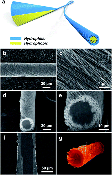
Herein, a novel family of core–sheath CNT (named CS-CNT) fibers was created by asymmetrically twisting an aligned CNT sheet with hydrophobic and hydrophilic CNTs at two sides (Fig. 1a). The core or sheath can be hydrophobic or hydrophilic, depending on the application requirement. As a demonstration in the following discussion, we focused on CS-CNT fibers with a hydrophobic core that provided both high mechanical strength and electrical conductivity and a hydrophilic sheath that made it easy to incorporate second phases with high electrochemical activities. When the CS-CNT fiber was used as a counter electrode to fabricate a fiber-shaped DSSC, a maximal power conversion efficiency of 10.00% has been achieved. To the best of our knowledge, it represents the highest power conversion efficiency among all kinds of fiber-shaped solar cells including but not limited to DSSCs.
Experimental section
Preparation of pristine CNT sheets and hydrophilic CNT sheets
Spinnable CNT arrays were synthesized via chemical vapor deposition. Pristine hydrophobic CNT sheets were drawn from the spinnable CNT arrays over a glass slide with two ends covered with glass strips solidly. The hydrophobic CNT sheets were treated with an oxygen microwave plasma under an oxygen gas flow rate of 300 sccm and a power of 300 W (Plasma System 690, PVA Tepla) to produce hydrophilic CNT sheets. The treatment time was varied from 5 to 40 min to tune the degree of hydrophilicity.Preparation and modification of CS-CNT fibers
The hydrophobic CNT sheet was first subjected to oxygen plasma treatment for the left or right part. An asymmetric twist was then made by using a motor to produce the CS-CNT fiber, e.g., a hydrophobic core and hydrophilic sheath. Different CS-CNT fibers with increasing hydrophilic CNT sheet content from 0 to 100 wt% were prepared. To demonstrate the advantage of the core–sheath structure, Pt-modified CS-CNT fibers were further synthesized by an electrochemical double potential step method with a platinum wire and Ag/AgCl electrode as counter and reference electrodes, respectively. The aqueous electrolyte consisted of 1 mM K2PtCl6 and 0.1 M KCl. The amount of Pt nanoparticles was determined by the consumed charge during the electrochemical reaction. The Pt-coated CS-CNT fiber was prepared by immersing the CS-CNT fiber in H2PtCl6·6H2O aqueous solution (concentration of 5 mg mL−1) for 10 min, followed by pyrolysis in air at 400 °C for 30 min. The Pt content was determined by the weight increase of the CS-CNT fiber after the H2PtCl6 pyrolysis. The resulting modified CS-CNT fibers were rinsed with deionized water and then dried at room temperature in ambient air prior to use.Fabrication of fiber-shaped DSSCs
A Ti wire (diameter of 127 μm) was modified with a TiO2 nanotube array via an anodic oxidation method at a voltage of 60 V for 6 h in 0.3 wt% NH4F/ethylene glycol solution containing 8 wt% H2O in a 40 °C water bath. Afterwards, the Ti wires were washed with deionized water and annealed at 500 °C for 1 h in air. Subsequently, the as-prepared wires were treated with 100 mM TiCl4 aqueous solution at 70 °C for 30 min and rinsed using deionized water. Finally, the modified wires were heated to 450 °C for 30 min, followed by immersion in a mixture of dehydrated acetonitrile and tert-butanol (1/1, v/v) containing 0.3 mM N719 dye for 16 h after the temperature decreased to 120 °C. The resulting dye-absorbed Ti/TiO2 wire serving as a photoanode was twined with a Pt-modified CS-CNT fiber or Pt wire to produce the fiber-shaped DSSC. The redox electrolyte containing 0.1 M lithium iodide, 0.05 M iodine, 0.6 M 1,2-dimethyl-3-propylimidazolium iodide and 0.5 M 4-tertbutyl-pyridine in dehydrated acetonitrile was used for testing under AM 1.5 illumination. The electrolyte for cyclic voltammetry characterization was a dehydrated acetonitrile solution consisting of 5 mM lithium iodide, 0.5 mM iodine and 0.05 M lithium perchlorate.Results and discussion
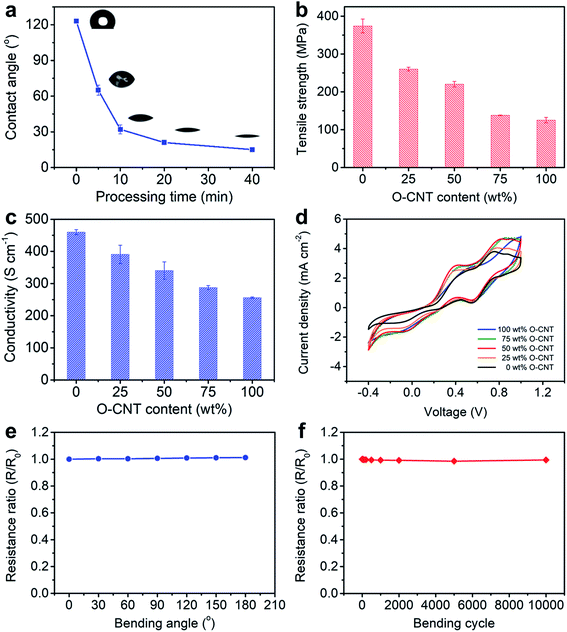
To prepare a CS-CNT fiber, an aligned CNT sheet was first pulled out of CNT arrays synthesized by chemical vapor deposition. The left side of the aligned CNT sheet was then submitted to oxygen microwave plasma treatment to produce hydrophilic CNTs (named O-CNTs) with the right side to be the as-prepared hydrophobic CNTs. After the above modification, no obvious damages were observed for the aligned structure of O-CNTs, confirmed by scanning electron microscopy (SEM) (Fig. 1b and c) compared with pristine CNTs (Fig. S1†). The weight ratio of hydrophobic core and hydrophilic sheath can be tuned by simply adjusting the width of O-CNTs in the sheet before twisting, offering a general and effective method to obtain various core–sheath fiber materials. For example, a core–sheath hybrid fiber with a Si sheath can be achieved by just replacing the O-CNT sheet with a Si-decorated CNT sheet. Here Si was introduced through an electron beam evaporation process. Fig. 1d and e show the cross section of a core–sheath fiber with 25% Si-incorporated CNTs outside at low and high magnifications, respectively. Non-destructive images of the core–sheath structure were also obtained from the dynamic lateral virtual slice of the core–sheath fiber using a 3D X-ray microscope (Fig. 1f). 3D spatial distribution of Si-modified CNTs was clearly observed via a 3D rendering sketch (Fig. 1g).Oxygen plasma interacted with CNTs by not only opening the double bonds but also introducing oxygen-containing functional groups onto the CNT surface,32,36 such as hydroxyl, carbonyl, ether and epoxy groups (Fig. S2†), which was also verified by the significant enhancement of the O 1s peak in the X-ray photoelectron spectra (Fig. S3†). Extending the oxygen plasma processing time from 0 to 40 min, the hydrophilic degree of CNTs went up with the water contact angle decreasing from 123° to 15° (Fig. 2a) due to the increased oxygen-containing functional groups. However, the damage of the π–π conjugated structure of CNTs resulted in the degradation of mechanical strength (Fig. S4†) and electrical conductivity (Fig. S5†) which both decreased severely at processing time beyond 40 min. Therefore, a processing time of 20 min was adopted and investigated later.
The CS-CNT fibers with different O-CNT contents were compared as counter electrodes of fiber-shaped DSSCs. As shown in Fig. 2b and c, the tensile strength and electrical conductivity of CS-CNT fibers decreased from 374 to 125 MPa and 460 to 256 S cm−1 when the O-CNT content increased from 0 to 100 wt%, respectively. Cyclic voltammograms (CVs) were compared for the catalytic activities of CS-CNT counter electrodes (Fig. 2d), which showed two pairs of oxidation/reduction peaks in each curve with the left pair corresponding to the redox action of I3−/I−. Typically, a more effective counter electrode yields a lower peak-to-peak voltage separation (Vpp) between the left pair and a higher peak current density. Interestingly, the introduced oxygen-containing functional groups together with the active defects can improve the electrochemical activity of CNTs.37,38 Compared with bare CNT fibers without the oxygen plasma treatment, the CS-CNT fibers demonstrated better performances in catalyzing the reduction of I3− to I− with Vpp dropping from 0.71 to 0.48 V when the O-CNT content increased from 0 to 50 wt%. However, Vpp increased to 0.59 V for the total O-CNT fiber probably due to the deterioration in electrical conductivity. Considering the mechanical strength, electrical conductivity and electrochemical activity, CS-CNT fibers with 50 wt% O-CNTs were mainly discussed if not specified below. The CS-CNT fiber was highly flexible with only 1.2% variation of the electrical resistance with bending angles varying from 0 to 180° (Fig. 2e). In addition, the electrical resistance remained almost unchanged after bending for 10![[thin space (1/6-em)]](https://www.rsc.org/images/entities/char_2009.gif) 000 cycles (Fig. 2f).
000 cycles (Fig. 2f).
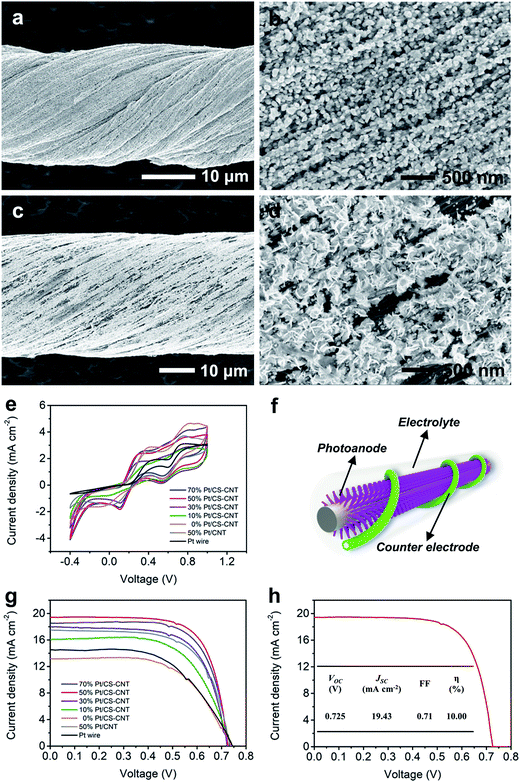
The O-CNTs can serve as effective platforms for further modification. Electrochemical deposition of Pt nanoparticles onto the CS-CNT fiber showed quite distinct morphologies from that onto a pristine CNT fiber (Fig. 3a–d). On one hand, the CS-CNT fiber had a hydrophilic sheath which made it easy for the aqueous electrolyte containing K2PtCl6 to diffuse deeper into the fiber and react with more CNT bundles without a pre-impregnation procedure. On the other hand, the oxygen-containing functional groups and active defects provided more nucleation sites for Pt nanoparticle deposition.31,34 As a result, the Pt nanoparticles presented a smaller particle size even when 50% Pt was deposited (Fig. 3a and b). The smaller Pt nanoparticles showed better electrochemical properties with the same loading amount,35 so the Pt-electrodeposited CS-CNT fiber (Pt/CS-CNT fiber) could catalyze the reduction of I3− more efficiently.
As expected, the Pt/CS-CNT fiber proved more effective as a counter electrode for fiber-shaped DSSCs. To optimize the catalytic activity of the CS-CNT fiber, the cyclic voltammograms of Pt/CS-CNT fibers with different Pt contents were compared. The Pt/CS-CNT fiber with 30% or more Pt nanoparticles produced lower and similar Vpp (Fig. 3e), while those with 50% and 70% Pt demonstrated higher peak current densities, i.e., higher catalytic activities. The J–V characteristic curves under AM 1.5 illumination were also compared for the fiber-shaped DSSCs (Fig. 3f and S6†) in Fig. 3g, the corresponding photovoltaic parameters of which are summarized in Table S1.† The open-circuit voltage (VOC) remained adjacent to 0.73 V, while the short-circuit current density (JSC) and the fill factor (FF) were both enhanced from 13.14 to 19.43 mA cm−2 and 0.60 to 0.71 with increasing Pt content from 0 to 50%, respectively. All photovoltaic parameters were slightly changed when Pt loading increased further. The optimized power conversion efficiency (η) was achieved at a Pt content of 50%.
Under the same conditions, the DSSC based on the as-synthesized CNT fiber without modification demonstrated a lower η of 4.17% (Fig. S7†). Note that if Pt was just coated on the surface of the CS-CNT fiber, the resulting DSSC showed an η of 7.21%, compared with 7.78% for the electrochemically deposited Pt/CS-CNT fiber (Fig. S8†). The electrochemically deposited Pt/CS-CNT fiber showed higher electrochemical properties than the Pt wire and Pt-electrodeposited bare CNT fiber (Pt/CNT fiber). As shown in Fig. 3e, the Pt/CS-CNT fiber with a Pt content of 50% showed a Vpp of 0.20 V rather lower than the Pt/CNT fiber counterpart (0.39 V) and Pt wire (0.57 V). To exclude the impact of electrode surface area, the normalized current densities at the reduction peak were provided, where the Pt/CS-CNT fiber presented a higher current density of −1.83 mA cm−2 compared with the Pt/CNT fiber (−1.49 mA cm−2) and Pt wire (0.50 mA cm−2). Moreover, the Pt/CS-CNT fiber could offer more active sites for the reduction of I3− due to a smaller nanoparticle size than the Pt/CNT fiber based on the same Pt amount (Fig. 3a–d). The η of the resultant cell was increased by 19% and 64% compared with the Pt/CNT fiber and Pt wire counterparts, respectively (Fig. 3g and Table S1†). A highest power conversion efficiency of 10.00% was obtained after optimization (Fig. 3h), which exceeded all other fiber-shaped solar cells.2–4,9–13,18–22,39,40 To fully understand the apparent high efficiency of the prepared fiber cells, further exploration is needed.
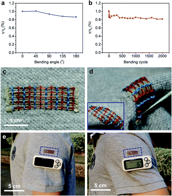
Besides the high power conversion efficiency, these fiber-shaped DSSCs were also flexible. The η was maintained at 86% under bending with increasing angle from 0 to 180° (Fig. 4a). After bending at 90° for 2000 cycles, the fiber-shaped DSSC could effectively work with only 18% of the initial power conversion efficiency sacrificed (Fig. 4b). The fiber-shaped DSSCs can be further woven onto flexible power textiles (Fig. 4c) and can also bear a variety of deformations like bending and twisting (Fig. 4d). They were demonstrated to power a pedometer effectively and steadily under outdoor sunlight (Fig. 4e and f).
Conclusion
In conclusion, a new family of hydrophobic core/hydrophilic sheath CNT fibers was designed to simultaneously realize high mechanical strength, electrical conductivity and electrochemical activity. When they were used as counter electrodes to fabricate fiber-shaped DSSCs, a record power conversion efficiency of 10.00% has been achieved. These novel fiber electrodes can also be widely explored for high-performance energy storage devices such as supercapacitors and aqueous lithium-ion batteries. This work may open up a new direction in the development of energy materials and devices with high properties.Conflicts of interest
There are no conflicts of interest to declare.Acknowledgements
This work was supported by MOST (2016YFA0203302), NSFC (21634003, 51573027, 51403038, 51673043, 21604012, 21503079), STCSM (16JC1400702, 17QA1400400, 15XD1500400, 15JC1490200) and SHMEC (2017-01-07-00-07-E00062).References
- Z. Wen, M.-H. Yeh, H. Y. Guo, J. Wang, Y. L. Zi, W. D. Xu, J. N. Deng, L. Zhu, X. Wang, C. G. Hu, L. P. Zhu, X. H. Sun and Z. L. Wang, Sci. Adv., 2016, 2, e1600097 Search PubMed.
- W. X. Song, H. Wang, G. C. Liu, M. Peng and D. C. Zou, Nano Energy, 2016, 19, 1–7 CrossRef CAS.
- L. B. Qiu, J. Deng, X. Lu, Z. B. Yang and H. S. Peng, Angew. Chem., Int. Ed., 2014, 53, 10425–10428 CrossRef CAS PubMed.
- N. N. Zhang, J. Chen, Y. Huang, W. W. Guo, J. Yang, J. Du, X. Fan and C. Y. Tao, Adv. Mater., 2016, 28, 263–269 CrossRef CAS PubMed.
- H. Sun, Y. Zhang, J. Zhang, X. M. Sun and H. S. Peng, Nat. Rev. Mater., 2017, 2, 17023 CrossRef CAS.
- Y. Huang, M. S. Zhu, Z. X. Pei, Q. Xue, Y. Huang and C. Y. Zhi, J. Mater. Chem. A, 2016, 4, 1290–1297 CAS.
- M. Wehner, M. T. Tolley, Y. Menguc, Y. L. Park, A. Mozeika, Y. Ding, C. Onal, R. F. Shepherd, G. M. Whitesides and R. J. Wood, Soft Robot., 2014, 1, 263–274 CrossRef.
- L. Migliorini, T. Santaniello, Y. S. Yan, C. Lenardi and P. Milani, Sens. Actuators, B, 2016, 228, 758–766 CrossRef CAS.
- Z. B. Yang, H. Sun, T. Chen, L. B. Qiu, Y. F. Luo and H. S. Peng, Angew. Chem., Int. Ed., 2013, 52, 7545–7548 CrossRef CAS PubMed.
- D. Y. Liu, M. Y. Zhao, Y. Li, Z. Q. Bian, L. H. Zhang, Y. Y. Shang, X. Y. Xia, S. Zhang, D. Q. Yun, Z. W. Liu, A. Y. Cao and C. H. Huang, ACS Nano, 2012, 6, 11027–11034 CrossRef CAS PubMed.
- L. B. Qiu, S. S. He, J. H. Yang, F. Jin, J. Deng, H. Sun, X. L. Cheng, G. Z. Guan, X. M. Sun, H. B. Zhao and H. S. Peng, J. Mater. Chem. A, 2016, 4, 10105–10109 CAS.
- J. F. Yu, D. Wang, Y. N. Huang, X. Fan, X. Tang, C. Gao, J. L. Li, D. C. Zou and K. Wu, Nanoscale Res. Lett., 2011, 6, 94 CrossRef PubMed.
- Z. B. Lv, J. F. Yu, H. W. Wu, J. Shang, D. Wang, S. C. Hou, Y. P. Fu, K. Wu and D. C. Zou, Nanoscale, 2012, 4, 1248–1253 RSC.
- K. Kakiage, Y. Aoyama, T. Yano, K. Oya, J. Fujisawa and M. Hanaya, Chem. Commun., 2015, 51, 15894–15897 RSC.
- F. W. Zhao, S. X. Dai, Y. Q. Wu, Q. Q. Zhang, J. Y. Wang, L. Jiang, Q. D. Ling, Z. X. Wei, W. Ma, W. You, C. R. Wang and X. W. Zhan, Adv. Mater., 2017, 29, 1700144 CrossRef PubMed.
- J.-P. Correa-Baena, A. Abate, M. Saliba, W. Tress, T. J. Jacobsson, M. Gratzel and A. Hagfeldt, Energy Environ. Sci., 2017, 10, 710–727 CAS.
- Z. T. Zhang, Y. Zhang, Y. M. Li and H. S. Peng, Acta Polym. Sin., 2016, 10, 1284–1299 Search PubMed.
- J. Liang, G. Y. Zhu, C. X. Wang, Y. R. Wang, H. F. Zhu, Y. Hu, H. L. Lv, R. P. Chen, L. B. Ma, T. Chen, Z. Jin and J. Liu, Adv. Energy Mater., 2017, 7, 1601208 CrossRef.
- L. Chen, H. X. Yin, Y. Zhou, H. Dai, T. Yu, J. G. Liu and Z. G. Zou, Nanoscale, 2016, 8, 2304–2308 RSC.
- H. Sun, X. You, J. Deng, X. L. Chen, Z. B. Yang, J. Ren and H. S. Peng, Adv. Mater., 2014, 26, 2868–2873 CrossRef CAS PubMed.
- X. Pu, W. X. Song, M. M. Liu, C. W. Sun, C. H. Du, C. Y. Jiang, X. Huang, D. C. Zou, W. G. Hu and Z. L. Wang, Adv. Energy Mater., 2016, 6, 1601048 CrossRef.
- Y. P. Fu, H. W. Wu, S. Y. Ye, X. Cai, X. Yu, S. C. Hou, H. Kafafy and D. C. Zou, Energy Environ. Sci., 2013, 6, 805–812 CAS.
- D. S. Yu, K. Goh, H. Wang, L. Wei, W. C. Jiang, Q. Zhang, L. M. Dai and Y. Chen, Nat. Nanotechnol., 2014, 9, 555–562 CrossRef CAS PubMed.
- Z. L. Dong, C. C. Jiang, H. H. Cheng, Y. Zhao, G. Q. Shi, L. Jiang and L. T. Qu, Adv. Mater., 2012, 24, 1856–1861 CrossRef CAS PubMed.
- M. F. L. D. Volder, S. H. Tawfick, R. H. Baughman and A. J. Hart, Science, 2013, 339, 535–539 CrossRef PubMed.
- J. T. Di, X. H. Zhang, Z. Z. Yong, Y. Y. Zhang, D. Li, R. Li and Q. W. Li, Adv. Mater., 2016, 28, 10529–10538 CrossRef CAS PubMed.
- K. Wang, Q. H. Meng, Y. J. Zhang, Z. X. Wei and M. H. Miao, Adv. Mater., 2013, 25, 1494–1498 CrossRef CAS PubMed.
- M. D. Lima, S. L. Fang, X. Lepro, C. Lewis, R. Ovalle-Robles, J. Carretero-Gonzalez, E. Castillo-Martinez, M. E. Kozlov, J. Y. Oh, N. Rawat, C. S. Haines, M. H. Haque, V. Aare, S. Stoughton, A. A. Zakhidov and R. H. Baughman, Science, 2011, 331, 51–55 CrossRef CAS PubMed.
- L. Geng, S. S. Xu, J. C. Liu, A. R. Guo and F. Hou, Electroanalysis, 2017, 29, 778–786 CrossRef CAS.
- F. Li, B. Cao, W. X. Zhu, H. Song, K. L. Wang and C. Q. Li, Catalysts, 2017, 7, 145 CrossRef.
- W. C. Fang, F. R. Chen, M. C. Tsai, H. Y. Chou, H. C. Wu and C. K. Hsieh, Surf. Coat. Technol., 2017, 320, 584–589 CrossRef CAS.
- Y. H. Rhee, D. J. Ahn, M. J. Ko, H.-Y. Jin, J.-H. Jin and N. K. Min, Electrochim. Acta, 2014, 146, 68–72 CrossRef CAS.
- Z. Q. Jiang, Z.-J. Jiang and Y. D. Meng, Appl. Surf. Sci., 2011, 257, 2923–2928 CrossRef CAS.
- J. Hu, L. Jiang, C. X. Zhang, X. D. Zhang, Y. D. Meng and X. K. Wang, Appl. Phys. Lett., 2014, 104, 151602 CrossRef.
- Z. Q. Jiang, X. Y. Yu, Z.-J. Jiang, Y. D. Meng and Y. C. Shi, J. Mater. Chem., 2009, 19, 6720–6726 RSC.
- S. S. He, P. N. Chen, L. B. Qiu, B. J. Wang, X. M. Sun, Y. F. Xu and H. S. Peng, Angew. Chem., Int. Ed., 2015, 54, 14880–14884 CrossRef CAS PubMed.
- J. D. Roy-mayhew, D. J. Bozym, C. Punckt and I. A. Aksay, ACS Nano, 2010, 4, 6203–6211 CrossRef CAS PubMed.
- Y. H. Xue, J. Liu, H. Chen, R. G. Wang, D. Q. Li, J. Qu and L. M. Dai, Angew. Chem., Int. Ed., 2012, 51, 12124–12127 CrossRef CAS PubMed.
- J. Liang, G. M. Zhang, W. T. Sun and P. Dong, Nano Energy, 2015, 12, 501–509 CrossRef CAS.
- J. Yan, M. J. Uddin, T. J. Dickens, D. E. Daramola and O. I. Okoli, Adv. Mater. Interfaces, 2014, 1, 1400075 CrossRef.
Footnotes |
| † Electronic supplementary information (ESI) available. See DOI: 10.1039/c7ta08637g |
| ‡ These authors contributed equally to this work. |
| This journal is © The Royal Society of Chemistry 2018 |


