 Open Access Article
Creative Commons Attribution 3.0 Unported Licence
Droplet impact dynamics on textiles
Gannian
Zhang
 a,
Miguel A.
Quetzeri-Santiago
a,
Corinne A.
Stone
b,
Lorenzo
Botto
a,
Miguel A.
Quetzeri-Santiago
a,
Corinne A.
Stone
b,
Lorenzo
Botto
 a and
J. Rafael
Castrejón-Pita
 *a
*a
aSchool of Engineering and Materials Science, Queen Mary, University of London, London E1 4NS, UK. E-mail: r.castrejonpita@qmul.ac.uk; Tel: +44 (0)20 7882 7620
bDefence Science and Technology Laboratory, Porton Down, Salisbury SP4 0JQ, UK
First published on 28th September 2018
Abstract
The development of textiles that repel droplets following droplet impact at a high velocity is a common requirement in a number of applications, ranging from waterproof clothing to inkjet printing, yet the underpinning physical mechanisms are not entirely understood. The impact of a droplet on the surface of a textile produces two simultaneous yet separate flows, occurring above and below the surface, and which are associated with the spreading and penetration dynamics. In this paper, we study the temporal evolution of the lateral spreading diameter of a droplet impacting both hydrophobic and hydrophilic textiles. We show that the impact on textiles at short timescales involves no deformation of the droplet shape if the textile's porosity is sufficiently low. We show that the early-stage impact penetration is solely driven by inertia and no lamella is visible. We also show that for hydrophilic textiles, depending on the impact conditions, a droplet can be captured by the textile or penetrate it. We show by balancing the dynamic impact and capillary pressures that the penetration behaviour is governed by a threshold pore size, the liquid characteristics and the droplet diameter. Our conclusions highlight that the ability of a textile to repel water is controlled by the mesh size. Our experiments and analysis were carried out on coated hydrophobic and non-coated hydrophilic textiles with four corresponding mesh sizes, and are in agreement with the previous findings on hydrophobic metallic (copper) meshes.
Introduction
The impact of liquid droplets on solid surfaces is ubiquitous in nature, such as raindrops striking the surfaces of soil1 and plants.2 In industrial environments, these impact dynamics are important in a wide range of applications, such as the design of functional surfaces for self-cleaning,3,4 ice repulsion,5,6 and the manufacturing of smart7 and protective8 clothing. Historically, researchers have extensively studied droplet spreading and receding,9 bouncing and splashing10–12 on smooth and rough solid surfaces, and on complex and smart substrates.13 Symmetric droplet splitting2,14 and pancake bouncing13 have been observed on solid surfaces with superhydrophobic ridges and micro-posts. More recently some authors have studied the impact of droplets on a sieve15 and on rigid metallic meshes16,38 concluding that the impact dynamics on these substrates depends on the impact speed and the substrate characteristics. However, the impact of droplets on textiles has received little attention. Previous studies on textiles have been confined to the qualitative comparison of bloodstain patterns following blood droplet impact on different textiles,17 and the estimation of the textiles’ impact stresses.18 Here we study the impact dynamics of liquid droplets on hydrophobic and hydrophilic nylon textiles. We first focus on the droplet spreading behaviour and next we determine the liquid penetration criterion in terms of the textile characteristics.The impact dynamics of droplets on solid substrates has received much attention due to its relevance in inkjet printing, pesticide and paint spraying, and other aerosol coatings. The fluid mechanical analyses have typically focused on the maximum spreading diameter, and on the splashing behaviour, as these aspects determine the quality of printing in inkjet and the coverage efficiency of sprays. Importantly, it has been found that the maximum spreading ratio  follows a power law of the form βmax ∝ Weα, where α ranges from 0.2 to 0.5; dmax and D are the maximum spreading and the initial droplet diameters, respectively, and We is the Weber number (defined as
  , ρ is the liquid density, v is the speed of impact, and σ is the surface tension). Recent studies19 have shown that, in the context of porous media, α is also affected by moisture. Using scaling arguments, Clanet et al.20 found that βmax is a function of We1/4 for both hydrophobic and hydrophilic surfaces for droplet impact in the range 2 ≤ We ≤ 900. In a different work, Lee et al.21 found that viscosity also affects βmax and proposed a relationship of the form
  based on a first-order Padé approximation,22 where βsessile is the spreading ratio at rest, Re is the Reynolds number
  ,23 and μ is the liquid dynamic viscosity. However, a consensus on whether the surface wettability affects βmax has yet to be reached. It has been argued that spreading ratio on surfaces such as stainless steel, glass and paraffin depends on the contact angle θ and is ruled by a critical Weber (We) number.24,25 Experimental data26 have shown that for We < 200, βmax decreases monotonically as a function of θ, while for We > 200, βmax varies with We1/5. In contrast, other evidence from droplet impact on plastic and glass substrates27 at We > 200 has proven that θ plays no role in βmax. In the context of solid meshes,20 a scaling dmax ∝ D·We1/4 has recently been found to describe the impact dynamics on non-wettable meshes with a solid fraction ϕ no smaller than 70%.16
Droplet impact on hydrophobic substrates have also been the focus of many recent studies. The reduction of the contact time between a droplet and a solid substrate during the impact is crucial to the design of self-cleaning and liquid repellent surfaces. Liquid repellency has been achieved by incorporating superhydrophobic micro-ridges14 and micro-wires28 on smooth surfaces to cause axi-symmetric droplet splitting upon impact. Experiments13 have shown that the droplet impact on micro-architectured tapered micro-posts results in either a pancake bouncing or a recoiling-bouncing regime. For straight posts, the liquid menisci are subjected to constant deceleration, resulting in droplet recoiling before bouncing. Other experiments have shown that irregular surface roughness results in diverse bouncing regimes, ranging from conventional spreading to partial bouncing due to droplet pinning on the roughness elements, or to the more rarely observed inverse jetting and bouncing with entrapped air bubbles.29 Superhydrophobic micro-patterned substrates can be invaded or flooded by liquid due to impact, evaporation or condensation,30 and such “invasion” can be promoted by local extreme roughness protrusions.31 Surface patterning leads to partial wetting and pinning of the liquid at the substrate surface. In this transition, a droplet goes from “floating” above the substrate to being impaled at the microposts.32 Whether a sessile droplet impales or floats depends on the architecture of the substrate, the cavity size, θ, and the roughness factor. Experimental evidence33 has shown that evaporation-based flooding is regulated by the droplet size, the interstices pitch, and the height of the micro-texture, favoring the impalement of small droplets into the micro-texture.
Droplet impact on porous media has received little attention, compared with the abundant research on impermeable solids. Existing papers15,34 on permeable solids have focused on droplet impingement normal to the substrates while assuming that the azimuthal (or lateral) spreading encounters no other pore on the solid. Lorenceau and Quéré15 studied the impact of millimetre-sized silicone oil droplets on a wettable solid surface presenting a hole ranging from 200 to 600 μm in diameter. A critical velocity above which a droplet penetrates the hole and forms a filament extending beyond the back surface was identified. Under some conditions, this filament elongates and ruptures, generating secondary (or satellite) droplets. A force balance between inertial, capillary and viscous effects produced a scaling relationship connecting the speed of impact, the liquid properties and the pore size. Importantly, experimental data found that wettability of the solid was irrelevant in this case. Delbos et al.34 studied the impact of millimetre-sized droplets on superhydrophobic sub-millimetre-sized capillary tubes and found three penetration regimes: no penetration, limited penetration and “slug formation”. For an impact at a high speed, most of the droplet volume would penetrate into the capillary tube and form a “liquid slug”. The “slug formation” is unique for capillary tubes, due to the typical high aspect ratios (length/diameter) of the tubes. In this past work, the authors balanced the dynamic pressure with the Laplace pressure at the bottom of the “slug” and found a critical impact velocity for this unique regime.
In the case of droplets impacting meshes, recent work35,36 have identified three impact regimes, namely ‘‘no penetration’’, ‘‘protrusion’’ and “complete penetration”. The critical velocity vc that divides no penetration from complete penetration is obtained by balancing the dynamic impact pressure Pd ∝ ρvc2 and the capillary pressure Pc ∼ σΓ/A, where A and Γ are the opening area and the perimeter of the mesh pore, thence vc scales as (σΓ/A)1/2. The protrusion is a unique transition where a portion of the droplet extends beyond the mesh pores temporarily. Moreover, vc was found to increase as the pore depth increases due to viscous dissipation.15 In the extreme penetration case, most of the droplet volume shoots out of the pores and forms liquid ‘slugs’ extending from the opposite surface of the mesh. A further study demonstrated that superhydrophobic meshes16 could effectively resist incoming droplets and eliminate protrusion. Droplet penetration in a superhydrophobic mesh is suppressed at a critical recoil velocity vr ∼ (σ/D)1/6(σΓ/A)1/3, indicating that penetration cannot be achieved by surface wettability alone. Additionally, ‘pancake bouncing’ was reported on superhydrophobic meshes.16,35
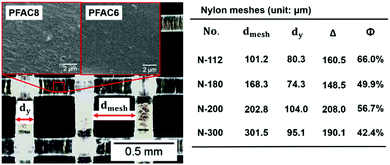
In another work, Bordoloi et al.37 studied the penetration of millimetre-sized water droplets (∼5 mm diameter) through a millimetric pore while the entire system was submerged in an oil tank. A thin oil film was found to separate the wall of the pore from the droplet for pores with rounded edges. In this case the surface wettability of the pore wall was found to have no effect on the penetration dynamics. In contrast, for pores with sharp edges, the droplets contacted the pore wall immediately after the impact and the surface wettability affected the penetration dynamics. Joung and Buie38 investigated the impact of droplets on thin porous films (i.e. papers) and found four impact outcomes ranging from droplet sticking to the impact surface to splashing, all dependent on the We number.44 While these past studies have focused on various solid substrates, scarce evidence exists on the impact dynamics on textiles. In fact, past studies have often focused on static wetting.39,40 In industrial environments, liquid repellency of textiles has been sought after using hydrophobic coatings but little attention has been paid to the liquid dynamics or the textile pore size. In addition, studies focusing on the contact line and impact dynamics before droplet recoiling, or on the early times after the initial contact between a droplet and a textile, are scarce. In this paper, we provide experimental data on the impact dynamics before receding, characterising the simultaneous yet separate lateral spreading and normal penetration, and compare the results with that for impacting impermeable solids and metallic meshes. We also show that penetration is possible for even hydrophobic textiles, and that the most critical parameters are the pore size, and the speed of impact. We study the impact of millimetre-sized droplets on various textiles including those whose surface has been treated to be hydrophobic (water repellent). Our experiments used nylon mono-filament textiles with pore sizes ranging from 100 to 300 μm. Our textiles were chemically treated with fluorinated coatings based on 1H,1H,2H,2H perfluorooctyl acrylate (PFAC6) and 1H,1H,2H,2H perfluorodecyl acrylate (PFAC8). These fluorinated coatings are widely known for the hydrophobic effects when applied to textiles, papers and other substrates.41 Microscopy indicates that the textile geometry, as shown in Fig. 1 and 2, i.e. pore size (dmesh) and yarn radius (Ryarn), is not affected by the chemical treatment. The hysteresis of the contact angle (advancing minus receding contact angle) on PFAC6 and PFAC8 films is reported to be 55° and 37°, respectively.39 Equilibrium contact angles are both approximately 123°, and therefore clearly indicating the hydrophobic nature of the perfluorinated polymers. The non-treated nylon textile is hydrophilic and the equilibrium contact angle is approximately 43°.
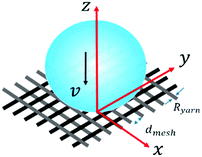 | ||
| Fig. 1 Schematic diagram of a droplet impacting a textile substrate (not to scale). The textile is placed perpendicular to the z-axis at z = 0, and the droplet moves along the z-axis. | ||
In this work, the impact of droplets on textiles was recorded using a high-speed imaging system and the obtained images were later analyzed for the extraction of the impact speed, the initial droplet diameter, the spreading diameter and the height of the droplet as a function of the time after impact. The recordings were also used to identify whether the droplet penetrated or stayed on the upper boundary of the textile. Our minimum optical resolution was 15.15 μm per pixel.
Experimental
Materials and methods
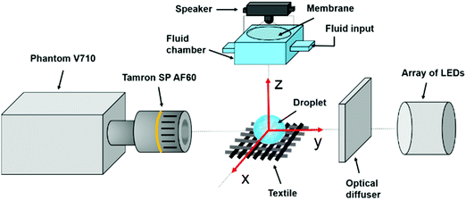
In this paper, we study the impact of aqueous glycerol droplets on nylon textiles. The working fluid is a solution of distilled water and pure glycerol (Sigma-Aldrich, assay of purity ≥99.5%, UK), with a measured surface tension of σ ≈ 68.5 ± 1.5 mN m−1 at room temperature. The textiles consist of nylon monofilaments aligned and intertwined at right angles to one another, forming pore sizes ranging from 100 μm to 300 μm. Textile surfaces were perfluorinated with PFAC6 and PFAC8 coatings using plasma treatment42 to render hydrophobicity. After the treatment, the textiles were cut into 20 × 8 mm2 sections. For every impact experiment, a textile section was horizontally clamped at its ends on a Deβen micro-test device. Through this device we applied a constant tensile force of 2.5 ± 0.1 N. The tensile force minimised the deformation of the textile in the direction normal to the textile plane. No change on the pore size was observed due to this stretching.A satellite-free droplet generator43,44 shown in Fig. 3, positioned right above the textile surface, was used to generate liquid droplets. In brief, the droplet generator consists of two parts: a loudspeaker and a liquid reservoir with a 2.0 mm diameter nozzle. The loudspeaker is used to send fast and short single pulses to generate millimetre-sized droplets. By adjusting the liquid meniscus position at the nozzle and controlling the pulse width and amplitude we could reliably control the speed of impact and size of droplets. We achieved a range of impact velocities within the range 0.88 to 1.90 m s−1. Droplet impact was visualised using a shadowgraphy system consisting of a high-speed camera (Phantom V710 with a Tamron SP AF60 macro lens), an optical diffuser, and a high-intensity illumination from an array of LEDS. Droplet impact was recorded at 64![[thin space (1/6-em)]](https://www.rsc.org/images/entities/char_2009.gif) 000 frames per second, a frame rate at least 3 times faster than previous relevant experiments.15,16,38 The exposure time was 10.0 μs for all experiments. Images were then analysed in ImageJ and Matlab. In all our experiments, the droplet size was kept constant at D ≈ 1.56 ± 0.12 mm.
000 frames per second, a frame rate at least 3 times faster than previous relevant experiments.15,16,38 The exposure time was 10.0 μs for all experiments. Images were then analysed in ImageJ and Matlab. In all our experiments, the droplet size was kept constant at D ≈ 1.56 ± 0.12 mm.
Results and discussion
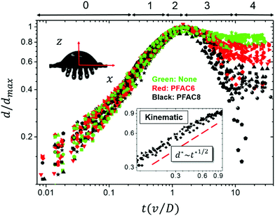
Various studies of droplets impacting porous substrates and meshes have been carried out in recent years focusing on the impact speed threshold for capture and penetration of a hole in a solid substrate,15 the droplet penetration speed in terms of pore size on porous films,38 and the droplet contact time on metallic meshes.16 In this paper, we study the radial spreading following the droplet impact on textiles and develop scaling arguments to obtain the penetration speed threshold in terms of the droplet diameters and the textile geometry.Past studies on droplets impacting non-porous surfaces have identified four stages in the impact process, namely kinematic (1), spreading (2), relaxation (3) and wetting/equilibrium (4) stages. For impact on a porous textile, we have identified an additional stage, which we have named penetration (0), occurring at the earliest time after impact. Our results for later times show a quantitative agreement with the kinematic stage. The spreading stage is observed in all the tested textiles and jetting conditions. The dynamics of the droplet in stages 2 to 4 were also found to be in agreement with previous results. In our analysis, the spread factor is defined as  , where dmax is the maximum spreading diameter, and d is the spreading diameter at time t. The experimental data, shown in Fig. 4 and subsequent figures, is reported as a function of the dimensionless time
  .
.
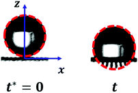
For textiles with pore size between 100 and 300 μm and We > 20, in the penetration stage (0 < t* < 0.25) the droplet passes through the textile but its shape remains spherical. This feature is illustrated in the insets of Fig. 5, where circular red dashed curves have been over imposed onto the planar projection of the droplet shape. The portion of the droplet that penetrates through the textile pores forms liquid filaments that extend out of the textile from the back surface, as seen in Fig. 5. The penetration stage has only been qualitatively characterized before on super-hydrophobic micro-grids.45 We can model the surface of the droplet during the penetration phase as a sphere of diameter D translating with velocity v in the negative z direction. Fig. 6 shows the xz projection of the droplet at two times: at the impact time (t* = 0) and at a time t. For our experimental conditions, the shape of the droplet before impact and at early times after impact can be approximated as a circle. The centre of this circle is found at a distance D/2 away from the surface, i.e. at  . The equation of such a circle is thus:
 | (1) |
 | (2) |
 | (3) |
| h = D − vt | (4) |
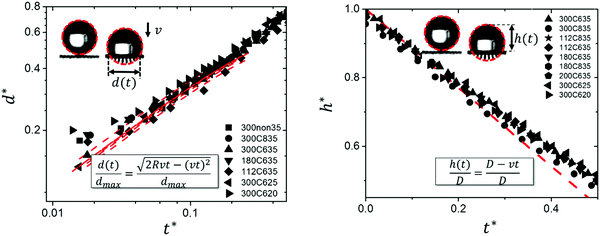 | ||
Fig. 5 Droplet penetration at very early times. The results show the droplet penetrating the textile with no shape variations. Here,  and and  . The legend indicates the textile mesh size in micrometres, the type of coating, and the We number, e.g. 300C635 stands for mesh size 300 μm, PFAC6 coating, and We ≈ 35. Penetration is not observed for We < 20. The dashed lines correspond to eqn (3) (left) and eqn (4) (right). Measurement error ±2 pixels. . The legend indicates the textile mesh size in micrometres, the type of coating, and the We number, e.g. 300C635 stands for mesh size 300 μm, PFAC6 coating, and We ≈ 35. Penetration is not observed for We < 20. The dashed lines correspond to eqn (3) (left) and eqn (4) (right). Measurement error ±2 pixels. | ||
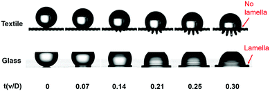
Eggers et al.23 carried out simulations of a droplet impacting a flat, impermeable, solid substrate. Their simulations show that the re-direction of the fluid momentum by the boundary from the normal to the lateral direction during impact is due to the development of a high-pressure region at the base of the droplet. The redirection of the flow is accompanied by a rapid pressure decay.23 For conventional impermeable substrates, the non-dimensional time t* for the pressure decay to commence is no greater than 0.1.12,23 For textiles, and other substrates with high porosity, the impact-generated pressure is expected to be much smaller than that for impenetrable substrates. Only when the droplet has penetrated sufficiently, the average pressure near the textile is sufficient large to cause the flow re-direction. As a result, the re-direction process in textiles is retarded in comparison to what happens on continuous impermeable solids, permitting us to capture stage 0 by high-speed imaging. Physically, the penetration stage is characterised by the lack of a lamella. In Fig. 7, we contrast droplet shapes corresponding to stage 0 (t* < 0.25) for the impact on a flat impermeable substrate and the impact on a textile. In the case of textiles, a liquid lamella does not form during the penetration phase and little lateral distortion of the droplet is seen while the droplet impacts and penetrates the textile. In fact, the formation of the lamella (t* ≈ 0.25) coincides with the transition to the kinematic stage (1).
Surface tension effects arise at the pace given by the capillary time:
 | (5) |
The droplet dynamics during the spreading phase is observed for all the textiles investigated here, regardless of the We number. Such finding agrees with previous experimental data for impact on non-porous solids; this data shows that the temporal development of d* changes significantly only when We is at least two orders of magnitude larger than in the cases explored here.46 Furthermore, our experiments show that dmax ≅ 2D. This result is also in agreement with literature results for non-porous solids.20
After reaching dmax, the “pancake” recedes, as the impact dynamics enters the relaxation stage 3. For non-porous substrates, this stage is known to be affected by the wettability of the substrate and contact angle hysteresis.48 Following stage 3, a comparatively long equilibrium stage (stage 4) occurs where the droplet volume stops receding and oscillates in the z direction. Eventually, the droplet finds a stable configuration. Fig. 4 shows that the rates at which the droplets recede are different for PFAC8 and PFAC6 textiles. Moreover, the equilibrium diameters for PFAC8 textiles are smaller. One can speculate that the smaller contact angle hysteresis41 of PFAC8 enables the contact line to move more freely.
Summarising, stages 1 to 4 are similar to those previously identified for impermeable solids46 whereas the penetration stage (stage 0), is unique to permeable substrates such as textiles. Visually, this stage is characterized by the lack of a liquid lamella at the droplet base.
As discussed, droplets impacting impermeable solids23,49 and some micro-textured substrates50 are compressed at the contact area, generating a high pressure field whose characteristic magnitude is of the order23 . It has been reported that the impact force on the solid substrate reaches its maximum51 at tmax ∼ D/8v, resulting in a pressure23P(tmax) ∼ 2ρv2. This peak pressure is often referred to as ‘‘water hammer’’ PWH and has been reported for the impact of droplets on non-wettable microtextured surfaces,50 microgrids45 and meshes.52 Essentially, PWH is generated due to the temporary volume compression at the bottom of the droplet at the moment of impact and is alleviated by the droplet lateral spreading.50 For non-wettable meshes, PWH has been found to scale as kρv2, where k is a scaling constant that depends on the mesh size.52 In our experiments, the textile porosity permits the penetration of the droplet and consequently the build-up pressure is lower than that found for solid substrates. In our experiments, the lamella is observed at much later times, so we claim the water hammer pressure does not contribute to the spreading dynamics in textiles.
The water hammer effect and the dynamic pressure have been found to follow the relationship:52
| PWH = aPD, | (6) |
Effect of mesh geometry on maximum spreading dmax
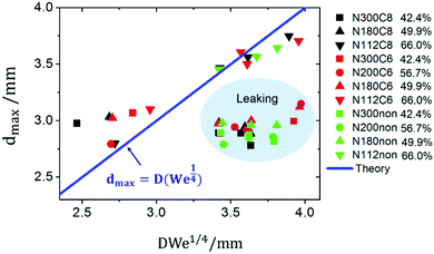
As discussed in the introduction, the maximum spreading diameter for droplets impacting super-hydrophobic solid surfaces20 and low porosity meshes,16 has been found to follow the scaling dmax ∝ D·We1/4. Our results, seen in Fig. 8, are consistent with this observation. The scaling dmax ∝ D·We1/4, solid line in Fig. 8 with a numerical coefficient equal to 1, is reasonably well followed by the data for densely packed textile fibres (solid fraction, ϕ > 66%), case for which penetration is not observed. In contrast, for cases showing penetration, the data does not adhere to the scaling. The experimental data, especially at relatively high We, shows significantly smaller values of dmax than those predicted by dmax ≈ D·We1/4, highlighting the non-negligible effect of the liquid penetration into the textile on lateral spreading.Two regimes of droplet penetration
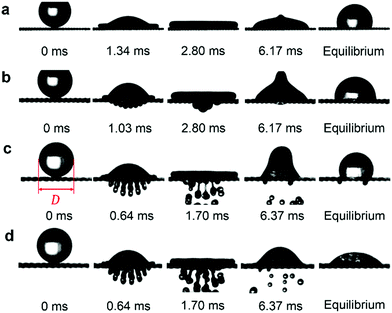
Through visualisation, we identified two distinctive regimes of droplet penetration: partial and complete (Fig. 9b and c). The former regime shows that a fraction of the droplet volume passes through the textile structure and then mostly retracts back to the (upper) impact surface. In contrast, in complete penetration the droplet extends beyond the textile squirting liquid filaments which eventually break into secondary droplets. Moreover, we found that the penetration regime is observed for droplet impacting on both hydrophilic and hydrophobic textiles, Fig. 9. In the partial penetration regime, PFAC6 textiles do not drive the penetrated volume back to the upper textile surface, leaving a droplet stain (or footprint) visible at the back surface. In contrast droplets impacting PFAC8 textiles in the partial penetration regime entirely retract leave the back textile surface non-wetted. As before, we presume that such phenomena is owed to the differences in contact angle hysteresis between PFAC6 and PFAC8. Interestingly, the equilibrium configurations in Fig. 9a and c show a contact angle of 123 ± 2°, despite having different impact dynamics. This observation confirms that evaluating liquid repellency solely on the equilibrium contact angle53 is clearly inappropriate, particularly for high-speed impact. A possible further study could explore the behavior of the dynamic contact angle in terms of the textile characteristics.Critical pore size for droplet penetration
It has been found that, viscous effects associated with the flow of liquid through a single pore play a minor role in resisting penetration, when the Reynolds number , where η is the dynamic viscosity.15 In our experiments, ρ ≈ 103 kg m−3, μ ∼ 10−2 Pa s, the typical impact velocity is vtypical ∼ 1 m s−1, and the characteristic pore size is dmesh ∼ 100 μm. Re ∼ 10, indicating that viscous effects are relatively unimportant in the impact regimes studied here. The capillary force exerted by the mesh pore35 scales as σdmesh, consequently, from the balance of fluid inertia and capillary forces, we deduce:
 | (7) |
 , we obtain:
 | (8) |
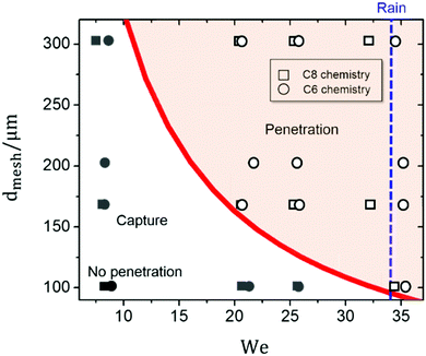
Based on eqn (8), we developed a penetration criterion based on the impact condition (Weber number) and the mesh size. Fig. 10 shows our experimental results for droplets impacting textiles for 7 < We < 37. The results in this figure are classified based on the penetration outcome, i.e. penetration or no-penetration (hollow or solid symbols).
Fig. 10 shows a clear separation of behavior in terms of the We number and the pore size. Eqn (8) seems to describe well the boundary between the penetration and no-penetration regions for k ≈ 0.24 (this scaling constant is determined when both D and dm are using the standard units: m). Our results are consistent with previous results16,35 obtained for hydrophobic and superhydrophobic copper meshes. For example, Ryu et al.35 showed that the onset of impact penetration for both hydrophobic and superhydrophobic meshes with mesh sizes dmesh > 178 μm and 3.5 mm water droplets, occurs for v ∼ 1 m s−1, i.e. We ≈ 35. Kumar et al.16 observed penetration for meshes with dmesh ≈ 140 and 280 μm at We ≈ 35 and 204.
The design and manufacture of modern raincoats, umbrellas and other general clothing include the use of hydrophobic woven textiles aiming to repel water while maintaining breathability. Our results indicate the contrary to popular belief; water repellency cannot be achieved by adjusting the fabric hydrophobic characteristics alone, as sufficiently rapid drops could penetrate a fabric regardless of its surface properties. A useful example to discuss is rain. A raindrop of a size drain ∼ 1.6 mm54 impacting at a speed of vrain ≅ 1.77 m s−1 penetrates any hydrophobic fabric with a pore size above 100 μm. A faster or a larger droplet will require a smaller pore to be repelled.
Conclusions
In this manuscript, high-speed imaging was used to investigate the droplet impact dynamics on textiles having varying pore sizes and two different hydrophobic and one hydrophilic wettabilities. A key insight into the impact dynamics is the identification of the penetration stage, corresponding to 0 < t* < 0.2. During this stage, the droplet penetrates the textile through the textile pores and forms liquid filaments under the textile surface. Interestingly, in this stage, the droplet shape above the textile is not perturbed by the impact and no lamella is observed. Our findings are supported by previous experimental results on metallic meshes.16,35The maximum spreading diameter dmax has been found to conform to the well-known scaling dmax = D(We1/4), which was initially developed for impermeable solids, for textiles with a solid fraction ϕ > 66%. This conclusion is in close agreement with the results by Kumar et al.16 (ϕ > 70%) on superhydrophobic meshes.
We have shown three regimes of droplet impact penetration on non-wettable meshes, namely ‘no penetration’, ‘capture’ and ‘complete penetration’. Balancing the dynamic impact pressure (∼ρv2) and the capillary pressure (∼σ/dmesh), the critical pore size has the form dmesh ∼ D/We. This simple model and our parametric experimental studies indicate that reducing the mesh size is an effective way to avoid liquid capture and penetration. This result is critical for the design of textiles aiming to avoid penetration hazardous liquids.
Conflicts of interest
There are no conflicts to declare.Acknowledgements
The authors acknowledge Prof. Alfonso A. Castrejón-Pita, of the University of Oxford, for his technical assistance. Prof. Asa H. Barber of London South Bank University is acknowledged for useful discussions and background work. This work has been financially supported by the Material Research Institute (MRI) of Queen Mary University of London, and the UK Defence Science & Technology Laboratory (Dstl). L. B. acknowledges ERC Starting Grant FlexNanoFlow (no. 715475). M. A. Q.-S. acknowledges the funding from the Mexican Energy Ministry (SENER) and the National Council for Science and Technology (CONACyT).References
- W. H. Wischmeier and D. D. Smith, Trans., Am. Geophys. Union, 1958, 39, 285–291 CrossRef.
- Y. Liu, M. Andrew, J. Li, J. M. Yeomans and Z. Wang, Nat. Commun., 2015, 6, 10034 CrossRef CAS PubMed.
- K. Liu and L. Jiang, Annu. Rev. Mater. Res., 2012, 42, 231–263 CrossRef CAS.
- R. Blossey, Nat. Mater., 2003, 2, 301–306 CrossRef CAS PubMed.
- L. Mishchenko, B. Hatton, V. Bahadur, J. A. Taylor, T. Krupenkin and J. Aizenberg, ACS Nano, 2010, 4, 7699–7707 CrossRef CAS PubMed.
- A. J. Meuler, G. H. McKinley and R. E. Cohen, ACS Nano, 2010, 4, 7048–7052 CrossRef CAS PubMed.
- C. Cao, M. Ge, J. Huang, S. Li, S. Deng, S. Zhang, Z. Chen, K. Zhang, S. S. Al-Deyab and Y. Lai, J. Mater. Chem. A, 2016, 4, 12179–12187 RSC.
- S. A. Brewer and C. R. Willis, Appl. Surf. Sci., 2008, 254, 6450–6454 CrossRef CAS.
- I. V. Roisman, R. Rioboo and C. Tropea, Proc. R. Soc. London, Ser. A, 2002, 450, 1411–1430 CrossRef.
- M. Rein, Fluid Dyn. Res., 1993, 12, 61–93 CrossRef.
- A. L. Yarin, Annu. Rev. Fluid Mech., 2006, 38, 159–192 CrossRef.
- R. Rioboo, M. Marengo and C. Tropea, Exp. Fluids, 2002, 33, 112–124 CrossRef.
- Y. Liu, L. Moevius, X. Xu, T. Qian, J. M. Yeomans and Z. Wang, Nat. Phys., 2014, 10, 515–519 Search PubMed.
- J. C. Bird, R. Dhiman, H.-M. Kwon and K. K. Varanasi, Nature, 2013, 503, 385–388 CrossRef CAS PubMed.
- É. Lorenceau and D. Quéré, J. Colloid Interface Sci., 2003, 263, 244–249 CrossRef PubMed.
- A. Kumar, A. Tripathy, Y. Nam, C. Lee and P. Sen, Soft Matter, 2018, 14, 1571–1580 RSC.
- E. M. Williams, M. Dodds, M. C. Taylor, J. Li and S. Michielsen, Forensic Sci. Int., 2016, 262, 66–72 CrossRef CAS PubMed.
- O. G. Engel, J. Res. Natl. Bur. Stand., 1955, 54, 281–298 CrossRef.
- J. Marston, J. E. Sprittles, Y. Zhu, E. Li, I. U. Vakarelski and S. T. Thoroddsen, Powder Technol., 2013, 239, 128–136 CrossRef CAS.
- C. Clanet, C. Béguin, D. Richard and D. Quéré, J. Fluid Mech., 2004, 517, 199–208 CrossRef.
- J. Lee, N. Laan, K. de Bruin, G. Skantzaris, N. Shahidzadeh, D. Derome, J. Carmeliet and D. Bonn, J. Fluid Mech., 2016, 786, R4 CrossRef.
- N. Laan, K. G. de Bruin, D. Bartolo, C. Josserand and D. Bonn, Phys. Rev. Appl., 2014, 2, 044018 CrossRef.
- J. Eggers, M. A. Fontelos, C. Josserand and S. Zaleski, Phys. Fluids, 2010, 22, 062101 CrossRef.
- M. Pasandideh-Fard, Y. Qiao, S. Chandra and J. Mostaghimi, Phys. Fluids, 1996, 8, 650–659 CrossRef CAS.
- T. Mao, D. Kuhn and H. Tran, AIChE J., 1997, 43, 2169–2179 CrossRef CAS.
- C. Antonini, A. Amirfazli and M. Marengo, Phys. Fluids, 2012, 24, 102104 CrossRef.
- B. L. Scheller and D. W. Bousfield, AIChE J., 1995, 41, 1357–1367 CrossRef CAS.
- A. Gauthier, S. Symon, C. Clanet and D. Quéré, Nat. Commun., 2015, 6, 8001 CrossRef CAS PubMed.
- P. Tsai, S. Pacheco, C. Pirat, L. Lefferts and D. Lohse, Langmuir, 2009, 25, 12293–12298 CrossRef CAS PubMed.
- A. Lafuma and D. Quéré, Nat. Mater., 2003, 2, 457–460 CrossRef CAS PubMed.
- D. Bartolo, F. Bouamrirene, E. Verneuil, A. Buguin, P. Silberzan and S. Moulinet, EPL, 2006, 74, 299 CrossRef CAS.
- M. Reyssat, A. Pépin, F. Marty, Y. Chen and D. Quéré, EPL, 2006, 74, 306 CrossRef CAS.
- J. Bico, U. Thiele and D. Quéré, Colloids Surf., A, 2002, 206, 41–46 CrossRef CAS.
- A. Delbos, E. Lorenceau and O. Pitois, J. Colloid Interface Sci., 2010, 341, 171–177 CrossRef CAS PubMed.
- S. Ryu, P. Sen, Y. Nam and C. Lee, Phys. Rev. Lett., 2017, 118, 014501 CrossRef PubMed.
- H. Ghadiri and D. Payne, Eur. J. Soil Sci., 1981, 32, 41–49 CrossRef.
- A. D. Bordoloi and E. K. Longmire, J. Fluid Mech., 2014, 759, 520–545 CrossRef CAS.
- Y. S. Joung and C. R. Buie, Phys. Rev. E: Stat., Nonlinear, Soft Matter Phys., 2014, 89, 013015 CrossRef PubMed.
- G. Zhang, R. Parwani, C. A. Stone, A. H. Barber and L. Botto, Langmuir, 2017, 12072–12079 CrossRef CAS PubMed.
- E. Kissa, J. Colloid Interface Sci., 1981, 83, 265–272 CrossRef CAS.
- Fluorinated polymers: Volume 1: Synthesis, Properties, Processing and Simulation, ed. B. Ameduri and H. Sawada, Royal Society of Chemistry, 2016 Search PubMed.
- S. Coulson, I. Woodward, J. Badyal, S. Brewer and C. Willis, J. Phys. Chem. B, 2000, 104, 8836–8840 CrossRef CAS.
- J. Castrejón-Pita, G. Martin, S. Hoath and I. Hutchings, Rev. Sci. Instrum., 2008, 79, 075108 CrossRef PubMed.
- J. Castrejón-Pita, N. Morrison, O. Harlen, G. Martin and I. Hutchings, Phys. Rev. E: Stat., Nonlinear, Soft Matter Phys., 2011, 83, 036306 CrossRef PubMed.
- P. Brunet, F. Lapierre, F. Zoueshtiagh, V. Thomy and A. Merlen, Appl. Phys. Lett., 2009, 95, 254102 CrossRef.
- R. Rioboo, M. Marengo and C. Tropea, Exp. Fluids, 2002, 33, 112–124 CrossRef.
- M. Vollmer and K.-P. Möllmann, Phys. Educ., 2012, 47, 664 CrossRef.
- C. Antonini, F. Villa, I. Bernagozzi, A. Amirfazli and M. Marengo, Langmuir, 2013, 29, 16045–16050 CrossRef CAS PubMed.
- D. Roux and J. Cooper-White, J. Colloid Interface Sci., 2004, 277, 424–436 CrossRef CAS PubMed.
- T. Deng, K. K. Varanasi, M. Hsu, N. Bhate, C. Keimel, J. Stein and M. Blohm, Appl. Phys. Lett., 2009, 94, 133109 CrossRef.
- D. Soto, A. B. De Lariviere, X. Boutillon, C. Clanet and D. Quéré, Soft Matter, 2014, 10, 4929–4934 RSC.
- J. Xu, J. Xie, X. He, Y. Cheng and Q. Liu, Exp. Therm. Fluid Sci., 2017, 82, 83–93 CrossRef CAS.
- A. Tuteja, W. Choi, M. Ma, J. M. Mabry, S. A. Mazzella, G. C. Rutledge, G. H. McKinley and R. E. Cohen, Science, 2007, 318, 1618–1622 CrossRef CAS PubMed.
- E. Villermaux and B. Bossa, Nat. Phys., 2009, 5, 697–702 Search PubMed.
| This journal is © The Royal Society of Chemistry 2018 |

