
 Open Access Article
 This Open Access Article is licensed under a Creative Commons Attribution-Non Commercial 3.0 Unported Licence
Dynamics of force generation by spreading platelets†
Jana
Hanke‡
a,
Dimitri
Probst‡
bc,
Assaf
Zemel
d,
Ulrich S.
Schwarz
 *bc and
Sarah
Köster
*ae
*bc and
Sarah
Köster
*ae
aInstitute for X-Ray Physics, University of Goettingen, Friedrich-Hund-Platz 1, 37077 Göttingen, Germany. E-mail: sarah.koester@phys.uni-goettingen.de
bInstitute for Theoretical Physics, Heidelberg University, Heidelberg, Germany. E-mail: schwarz@thphys.uni-heidelberg.de
cBioQuant-Center for Quantitative Biology, Heidelberg University, Heidelberg, Germany
dInstitute of Dental Sciences and Fritz Haber Center for Molecular Dynamics, Hebrew University of Jerusalem, 91120, Israel
eGerman Center for Cardiovascular Research (DZHK), Partner Site Göttingen, Germany
First published on 12th July 2018
Abstract
In order to gain more insight into the role of human platelets for blood clot formation, here we investigate the dynamics of force generation by platelet spreading onto elastic substrates of variable stiffness. Despite their small size, platelets generate high and rapidly varying traction forces on their extracellular environment, which we reconstruct with adapted implementations of Fourier transform traction cytometry. We find that while the final spread area is reached within a few minutes, the build-up of forces typically takes 10–30 minutes. In addition, we identify two distinct behaviors of individual cells, namely oscillating and non-oscillating platelets. An eigenvalue analysis of the platelet dipole tensor reveals a small anisotropy of the exerted force, which is compatible with a random distribution of a few force transmitting centers, in agreement with the observed shapes and traction patterns. We find a correlation between the maximum force level a platelet reaches and its spread area, which we explain by a thin film model for the actively contracting cell. The model reveals a large internal stress of hundreds of kPa. Experimentally we do not find any statistically relevant relation between the force level reached and the substrate stiffness within the stiffness range from 19 to 83 kPa, which might be related to the high platelet activation level used in our study. In addition, our model suggests that due to the uniquely small thickness of platelets, their mechanosensitivity might be limited to a lower stiffness range.
1 Introduction
Platelets are the key cellular players in blood clotting.1 Originating as fragments from megacaryocytes, they are the smallest cells found in the human body, with a diameter between 2 and 5 μm and a typical thickness of 1 μm in the resting state.1 They possess neither a nucleus nor a microtubule-organizing center, but otherwise contain the complete cytoskeletal machinery, including actin and myosin that is crucial for cellular processes such as spreading, contraction and migration. They are discoid in the resting state due to the presence of the microtubule-based marginal band. After activation, e.g. through thrombin or ADP, they become spherical due to coiling of the marginal band under increased actomyosin tension.2,3 Upon spreading onto a surface, platelets dramatically change their shape again, now into a flat appearance, finally reaching an average spread area of about 30 to 40 μm2 and a height of only a few tens of nm.4Physiologically, the platelet spreading process is an early step of blood clot formation and is followed by contraction of the cells. Contraction remodels the forming clot and allows normal blood flow to be re-established by pulling the clot mass towards the vessel wall.5 The involvement of the actomyosin system in these processes has been demonstrated by a rheological approach6 and by studying myosin IIA knock-out mice with impaired clot retraction.7 Importantly, activated platelets exert surprisingly large forces onto the surrounding tissue. The emerging forces have first been investigated by measuring clot retraction8 and contraction.6,9 However, it is likely that not all platelets in a clot are attached equally well to the disordered fibrin matrix and contract equally strongly within the clot. Thus, single cell approaches provided more quantitative insight into platelet force generation.
It has been shown by atomic force microscopy (AFM) that within a few minutes single platelets can build up average forces of 29 nN, which they can maintain for about 15 min.10 Using traction force microscopy (TFM) on soft elastic substrates, similar values were found, with single platelets generating 34 nN on a 25 min timescale.11 Recent work with DNA-based tension sensors has shown that traction forces are required to promote full platelet activation through the platelet integrin–fibrinogen bond12 and that traction maps are often anisotropic.13 Both studies showed that the force on single integrin–fibrinogen bonds can be surprisingly high, even exceeding 50 pN. An earlier study using elastic substrates has suggested that platelets are mechanosensitive and adapt their spreading area to extracellular stiffness,14 as has been observed before for adherent tissue cells,15,16 but it did not establish the exact threshold value nor did it measure the actual forces or consider the dynamics of traction generation.
Here we advance the current state of TFM to provide more insight into the dynamics of force generation by single platelet spreading onto soft elastic substrates. In general, generation of contractile forces exerted on the environment is vital for numerous biological processes such as spreading, migration and differentiation.15–18 Thus, multiple variants of TFM have been developed to quantify these forces on the single cell level.19–21 Because platelets are so small and their internal organization is difficult to image during TFM, one cannot use much additional real space information, like in model-based TFM.22 Thus, it is most appropriate to use unconstrained Fourier Transform Traction Cytometry (FTTC), which reconstructs two-dimensional traction forces without any further assumptions.23
To account for the high variability of force levels during platelet spreading and contraction, it is mandatory to apply methods that reliably reconstruct traction over the relatively long time scale of 30 min. Whereas most TFM-studies only consider a stationary traction force field, some reports have extended the method also to time-resolved TFM.11,15,24–27 Usually this is done by comparing each deformation image with the same reference image taken either before or after the complete time course. For the platelet case, however, this is not possible because deformations are too strong so as to establish each time anew the relation to the same reference image.
In order to meet these technical challenges for TFM on platelets, here we employ two FTTC-algorithms, one that smooths noisy data and one that uses regularization, and calibrate them against each other. Each of the two algorithms reconstructs the traction time series by comparing subsequent deformation images, thus avoiding the need to align each deformation image with the same reference image. With these methodological advances, we are able to reliably study the dynamics of force generation of human blood platelets over 30 min on substrates of various stiffnesses.
We first establish that the time scales for spreading (10 min) and force generation (30 min) are not the same and that one group of cells shows oscillating force-behavior and another does not. Neither of these groups adapts its spread area to the surrounding stiffness within the investigated range of 19 to 83 kPa, and both are characterized by force hot spots and slightly anisotropic force field dynamics. The force an individual platelet generates scales with the final spread area it reaches as predicted by modelling the platelet as a thin elastic disc that actively contracts its environment.28,29 The model allows us to estimate the magnitude of the internal stress generated in the platelet cytoskeleton. Interestingly, we find it to be hundreds of kPa, demonstrating the high level of contractility in these small cells.
2 Materials and methods
2.1 Platelet isolation
All experiments were performed in compliance with the relevant laws and institutional guidelines and were approved by the Ethics Committee of the University Medical Center Göttingen, votum 11/11/09 (“Untersuchung der Krafterzeugung und -transduktion in Trombozyten”) based on the Declaration of Helsinki. We used samples without any personal information about the donors as it is irrelevant for our study. Therefore, the criteria for the selection of donors are identical as for normal blood donation. Informed consent of the donors was obtained during blood donation. The platelets were isolated from human blood plasma concentrates taken from healthy donors at the Blood Donation Center of the University Clinic of Göttingen. A full description of the isolation procedure can be found elsewhere.11,30,31 Briefly, 4 mL of platelet concentrate was mixed with prostaglandin E1 (Cayman Chemical Company, Ann Harbor, MI, USA; final concentration 2.6 μg mL−1) and centrifuged at 480 × g and 21 °C for 20 min. The supernatant was removed and the cells resuspended in PSG (Pipes Saline Glucose: 5 mM PIPES, 145 mM NaCl, 4 mM KCl, 1 mM MgCl2·6H2O, 5 mM glucose, and 0.05 mM Na2HPO4). The centrifugation step was repeated twice with resuspension in 1 mL Hepes–Tyrode buffer containing bovine serum albumin (BSA) (134 mM NaCl, 12 mM NaHCO3, 2.9 mM KCl, 1 mM MgCl2, 5 mM HEPES, 5 mM glucose, and 0.34 mM Na2HPO4, pH 7.4, supplemented with 5 mg mL−1 BSA (Macs BSA stock solution, Milteny Biotech, Bergisch Gladbach, Germany)) after the last centrifugation step.2.2 Staining
For determination of the time point of attachment, platelets were stained with CellMask DeepRed (649/666 nm, Thermo Fisher Scientific Inc., Waltham, MA, USA). The dye was diluted in Hepes–Tyrode buffer containing BSA to a final concentration of 2.5 μg mL−1. 1 mL of platelet working solution was prepared by mixing the diluted dye with the isolated platelet solution to a final cell concentration of 2 × 10⁷ cells per mL. The working solution was incubated for 5 min at 37 °C and 5% CO2 before Prostaglandin E1 at a final concentration of 2.6 μg mL−1 was added and the platelets were centrifuged at 480 × g for 5 min at 21 °C. Subsequently, the platelets were re-suspended in Hepes–Tyrode for 5 to 10 min before imaging. Fixed platelets (after 10 min of thrombin stimulation) were stained for actin using Abberior STAR 635 Phalloidin (Abberior, Göttingen, Germany) on PAA gels. The images were recorded using a 100× oil immersion objective (Olympus, Hamburg, Germany, NA 1.4).2.3 Polyacrylamide gel preparation
The polyacrylamide (PAA) substrates were fabricated similarly to previous protocols.11 Cleaned cover slips (24 × 24 mm, thickness no. 1 (130–160 μm)) were first treated with 0.1 M NaOH before being incubated with APTMS (3-aminopropyltrimethoxysilane; Sigma-Aldrich, St. Louis, Missouri, USA) for 5 min. After washing and drying, the cover slips were treated with glutaraldehyde (0.5%, Polysciences Inc., Warrington, PA, USA) in PBS (phosphate buffered saline) for 30 min. Simultaneously, circular cover slips, 18 mm in diameter, were coated in Plus One Repel Silane (GE Healthcare, Little Chalfont, UK) for 5 min. The circular cover slips were washed in 70% ethanol followed by ultra pure water. PAA solutions were prepared by mixing acrylamide (40%, Bio-Rad Laboratories Inc., Hercules, CA, USA), bisacrylamide (2%, Bio-Rad) and PBS. The ratio between acrylamide and bis-acrylamide determines the final stiffness of the polymerized gel. The values used in this study are listed in Table S1 in the ESI.† 15 μL of 40 nm diameter green fluorescent beads at a concentration of 0.2% solids (FluoSpheres, carboxylate-modified microspheres, 505/515 nm, Thermo Fisher Scientific Inc.) was added to the mixture for a final volume of 500 μL. 7.5 μL of the bead containing mixture with added TEMED (N,N,N′,N′-tetramethylethane-1,2-diamine, Bio-Rad) and APS (Ammonium persulfate, Bio-Rad) was applied to each circular cover slip and covered by a square cover slip. The gels were polymerized for 60 min. By turning the gels upside-down while polymerizing we achieved two distinct layers of beads, one at the upper surface of the gel and one sticking to the bottom cover slip, as confirmed by confocal microscopy. Thus, even though confocal microscopy was not applicable due to the high sensitivity of the platelets to light and their fast contraction dynamics, we made sure that the recorded beads were positioned mostly in a single plane. Subsequently, the circular cover slips were carefully removed from the gels. The gels were treated twice with Sulfo-SANPAH (0.4 mM in Hepes, pH 8, ThermoFischer Scientific Inc.) for 8 min each under UV light to achieve a uniform coverage of the the gel with protein. This was followed by incubation with fibrinogen (0.1 mg mL−1, Calbiochem-Merck KGaA, Darmstadt, Germany) overnight at 4 °C. The following morning, the substrates were washed and kept immersed in PBS at 4 °C until further use. Gels were, on average, 35 μm thick and only gels of at least 20 μm thickness were used. The height of each gel was measured with the microscope as the distance between the upper and lower bead layer.2.4 Traction force microscopy
All experiments were conducted on an inverted research microscope (IX81, Olympus) using a 60× oil-immersion objective (UPlanSApo, NA 1.35, Olympus). The recordings were performed using a QImaging Retiga 6000 CCD camera (QImaging, Surrey, BC, Canada). The substrates were washed with Hepes–Tyrode buffer containing BSA before usage. To guarantee physiological conditions of 37 °C and 5% CO2 during the experiments, an incubation chamber (Tokai Hit, Ltd Co., Shizuoka, Japan) was mounted onto the microscope. The sample slides were fixed inside the chamber and kept moist until use. A sketch of the set-up is shown in Fig. 1A.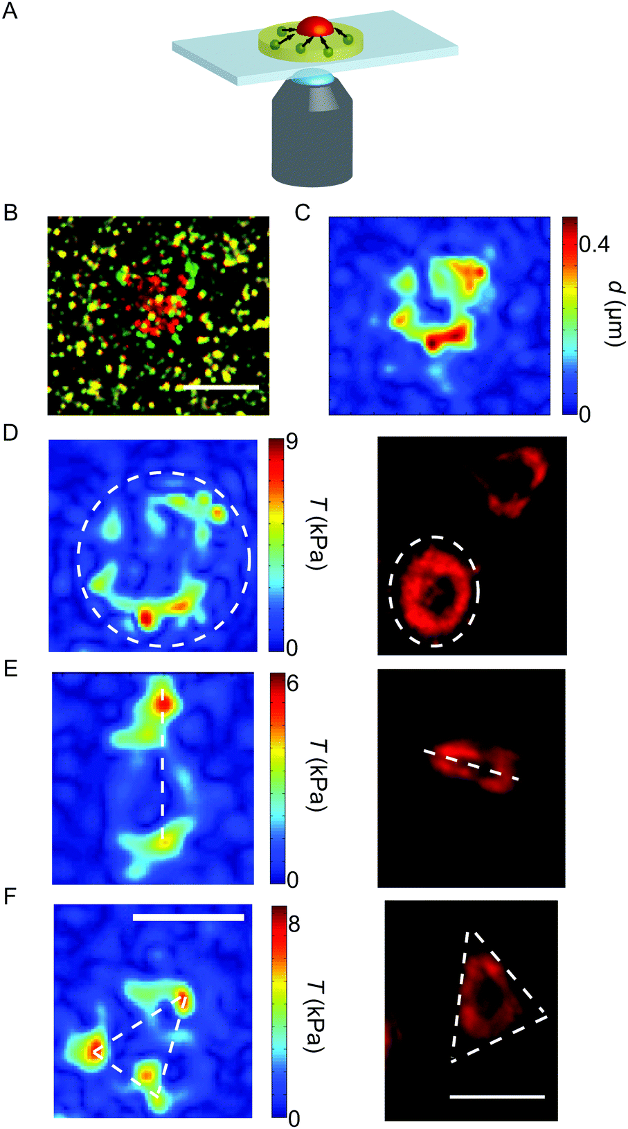 | ||
| Fig. 1 (A) Sketch of the experimental set-up. The deformations in the substrate (yellow) due to the contraction of the platelet (red) can be traced by the movement of the embedded beads (green). (B) Overlay of the unstrained substrate (green beads) and the deformed substrate (red beads). (C) The measured displacement field at the final time point. (D–F) Examples of force hot spot distributions (left) and actin structures (right). Typically, we find elliptic/circular (D), spindle-like (E) or triangular (F) shapes. The white dashed lines serve as a guide to the eye. Note that the respective left and right images do not show the identical individual platelet. Scale bars 5 μm. | ||
Membrane-stained platelets were placed on the substrates and stimulated with thrombin (thrombin from human plasma, Sigma-Aldrich; diluted in Hepes–Tyrode buffer, a final concentration of 4 u mL−1).31 Physiological thrombin concentrations differ within a wide range32 and here we chose a relatively high concentration to ensure maximum activation.9 Recordings were performed using a FITC/Cy5 dual-band filter with excitation maxima at 470 nm and 628 nm (AHF Analysentechnik AG, Tübingen, Germany) combined with an emission filter of wavelengths 537 nm and 694 nm (AHF Analysentechnik AG). Movies were recorded by taking an image of the bead positions (FITC) and the cell membrane (Cy5) every 7.5 s (0.13 fps) for 30 min after the addition of thrombin for imaging both the bead pattern in the gel and the fluorescently stained cell membrane. The time point of attachment t0 was defined individually for each platelet by careful inspection of fluorescence microscopy recordings of the membrane-stained cells and verified by the subsequent increase in the force curves (see below). As a light source, a xenon arc lamp (MT-ARC/XE, Olympus) was employed at 23% intensity; the exposure time was 50 ms. For analysis, only platelets were considered which were spatially isolated from other adherent platelets during contraction to exclude cell–cell interactions. Furthermore, only cells with a defined attachment time point were taken into account as the corresponding frame was later considered as the relaxed, un-deformed reference image at the starting point of the time series. An example of the substrate deformation is shown in Fig. 1B.
2.5 Data analysis
Typically, elastic substrates with embedded fluorescent marker beads are employed in TFM. By tracking their displacement with image processing techniques, spatially resolved traction force fields can be calculated solving the inverse problem of substrate deformation under surface traction. The individual methods differ both in data acquisition and in the subsequent data analysis. For tracking substrate deformations, the most common choices are particle image velocimetry (PIV), particle tracking velocimetry (PTV) and optical flow, using e.g. the Kanade–Lucas–Tomasi feature tracker.19 For traction reconstruction, one can distinguish between many different approaches, including 2D versus 3D force reconstruction and real space versus Fourier space reconstruction.20 The overall reconstruction quality depends strongly on the way the different elements work together in the final TFM-pipeline.33Due to the technical challenge of reconstructing platelet tractions over a long time, especially considering their very strong forces despite their small size, here we have developed two complementary methods that can be calibrated against each other. Most importantly, the presented algorithms are independent of the time interval for which data are available and are in principle not restricted by the cell size or the magnitude of the exerted forces. We present one algorithm that uses smoothing to deal with the noisy data and is based on PIV34 as used previously in connection to TFM24,35 (the smoothing-based approach). We extend the approach by including the tracing of massless Lagrangian markers as used in fluid dynamics.36 We then compare the results to the outcome of an algorithm based on optical flow, which tracks prominent features in the fluorescent images rather than matching patterns in sub-windows as does PIV. Therefore, this approach requires solving the ill-posed inverse problem of TFM with regularization (the regularization-based approach).
Considering the high forces on very small areas observed during platelet contraction, we had to adapt the way in which we detect the bead displacements. Typically, for larger cells and/or lower forces, each image of the deformed gel is compared directly to the un-deformed gel, using an image taken either at the beginning or the end of the experiment.15,24,25 In our case, the deformations are too large and too localized so as to be able to match bead patterns over the entire recording interval and we thus implemented an adapted algorithm that accounts for this peculiarity.
Our methods for data analysis are described in detail in the ESI† (part 2 and Fig. S1 and S2). For the smoothing-based approach, PIV analysis was performed in MATLAB (MATLAB R2009b, The Mathworks, Natick, MA, USA) using the MATLAB toolbox mPIV (http://www.oceanwave.jp/software/mpiv). First, images were filtered and drift-corrected. As the reference frame of the un-strained gel, the bead position at cell attachment was defined. To account for the fast contraction velocity, pairs of successive images were compared in each step contrary to the standard procedure of direct comparison to the un-strained case. For the PIV algorithm, the images were divided into sub-windows on a regular grid of 40 by 40 pixels or 32 by 32 pixels, depending on the speed of contraction, with 50% overlap. Calculating the intensity cross-correlation between sub-windows at equal position and considering the time difference in between successive frames yields the instantaneous mean velocity within the considered area. The cross-correlation between the windows was first calculated forwards in time, and then backwards in time; both values were averaged to reduce statistical noise. Sub-windows with missing velocity vectors due to e.g. bead clustering were interpolated using the nearest neighboring windows. To determine the displacement field relative to the reference frame, Lagrangian markers were distributed on the first frame on a regular 2 × 2 pixel grid without any interactions between them. Given their starting position and the current velocity fields, we could trace the markers over time using a combination of the implicit mid-point method and fixed-point iteration. Note that this approach is symplectic. From this displacement field we calculate the traction force fields using the FTTC algorithm as described in ref. 33 and 37 without the use of explicit regularization. Examples for a displacement field calculated with the Lagrangian markers and for typical traction force maps are shown in Fig. 1C and D–F, respectively.
For the regularization-based approach, optical flow analysis was performed in Python (Python 2.7.13, Python Software Foundation, Wolfeboro, New Hampshire, USA) using optical flow routines from OpenCV (Open Source Computer Vision Library, https://github.com/itseez/opencv, 2015), namely the Shi–Tomasi corner detection38,39 and the pyramidal Kanade–Lucas–Tomasi optical flow algorithm.40,41 Here, as well, we always compared two consecutive images thereby anticipating large displacements within short time intervals. Images were down-sampled from 16 to 8 bit. We used the Shi–Tomasi algorithm to identify no more than 1000 features to track, corresponding to the beads in the gel. To avoid double counting of clusters, a minimum distance of 3 pixels between features was established. Given the starting position of the beads, we could track the displacements between successive images of each feature and reconstruct the complete trace with reference to the time point of attachment. Applying the Kanade–Lucas–Tomasi algorithm, the intensity gradients in small sub-windows around the beads were tracked from one frame to the next. This was again done once forwards and once backwards in time and the result averaged to reduce noise. As a starting point, the sub-windows had a size of 64 by 64 pixels, which was reduced to 32 by 32 pixels in a second run. Between frames, we assumed linear movement inside our windows using an Euler forward approach. At the border, a Tukey window42 of α = 0.2 was applied to ensure a border of zero velocity. Drift correction was conducted by choosing a small area, in which the expected displacement was 0, and the calculated displacement was subtracted from all calculated displacements. Lastly, the displacements were mapped onto a regular grid before determining the traction force fields. Traction forces were calculated using the regularized FTTC algorithm as described in ref. 33 and 37. Here we used Tikhonov regularization with a modified generalized cross-validation approach (R1GCV).43
For comparison of the temporal evolution of the contractile behavior, we used the quantity “total force” defined by  , where
 ![[T with combining right harpoon above (vector)]](https://www.rsc.org/images/entities/i_char_0054_20d1.gif) (
(![[x with combining right harpoon above (vector)]](https://www.rsc.org/images/entities/i_char_0078_20d1.gif) ) is the traction force at a given position and AROI defines a region of interest that contains all forces attributed to the cell contraction.24,26,27,44 As an alternative to the total force, the substrate strain energy defined as
) is the traction force at a given position and AROI defines a region of interest that contains all forces attributed to the cell contraction.24,26,27,44 As an alternative to the total force, the substrate strain energy defined as  , containing both traction force vectors and the corresponding displacement vectors
 ![[d with combining right harpoon above (vector)]](https://www.rsc.org/images/entities/i_char_0064_20d1.gif) , can also be used to compare individual cells.35 In our data, the total force and energy curves show exactly the same features. We only included contraction data with a calculation error smaller than 10% (for details of the error estimation, see ESI,† part 2.3 and Fig. S3). Most importantly, we find that both methods lead to the same results with regard to the spatial distribution and temporal evolution of the forces (see Fig. S4, ESI†).
, can also be used to compare individual cells.35 In our data, the total force and energy curves show exactly the same features. We only included contraction data with a calculation error smaller than 10% (for details of the error estimation, see ESI,† part 2.3 and Fig. S3). Most importantly, we find that both methods lead to the same results with regard to the spatial distribution and temporal evolution of the forces (see Fig. S4, ESI†).
3 Results
3.1 Different platelets show different dynamic patterns of force generation
The representative force reconstructions shown in Fig. 1D–F (left) demonstrate that platelets exert forces in different geometrical patterns, but that they are always concentrated at the edges of the cell. Strikingly, forces are typically exerted onto the substrate at “hot spots” which are stable in position over time, but may, for some cells, vary in magnitude with time. These hot spots often seem to be located at the corners of the traction-bearing regions. Interestingly, very similar shapes as observed in the traction maps are also observed in platelets stained for actin, as shown in Fig. 1D–F (right).We next investigated the temporal development of the platelet forces. Fig. 2A shows three representative examples for Ftot(t) curves. In each case, the recorded movies are 30 minutes long, but have been shifted such that at t0 = 0 s they all start with very small force. Strikingly, the dynamics of total force can show very different features, as shown by the three selected trajectories. (i) The magenta curve exhibits a rapid increase in force until about 500 s after adhesion and oscillates with a frequency of about 13 mHz. (ii) The blue curve, by contrast, shows force data which increase and then reach a plateau. (iii) The green curve, finally, shows similar initial behavior to the blue one, but then relaxes again. However, due to the finite recording time for each movie, we cannot exclude that those data curves that plateau or oscillate relax at a later time point after the recording has ended.
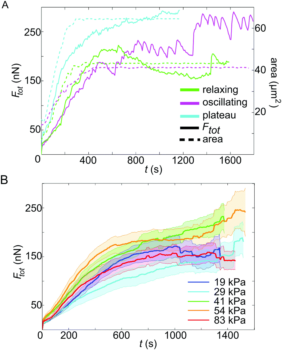 | ||
| Fig. 2 (A) Contractile behaviors of platelets: representative force traces for cells relaxing after reaching a maximum force (green), cells oscillating around a mean force (magenta) and cells reaching a force plateau (blue). The solid lines show the total force, whereas the dashed lines denote the spread area versus time. These behaviors are observed for all substrate stiffnesses and the examples shown here are for three platelets on 54 kPa gels. (B) Averaged total force data for five different substrate stiffnesses (solid lines, for the color code, see the legend), including the standard error (transparent area). | ||
For this study, we investigated platelets on five different substrate stiffnesses, as discussed in more detail below, and, interestingly, we observe all three force dynamics on all substrate stiffnesses, with percentages of 39%, 59%, and 22%, respectively, and no clear dependence on substrate stiffness. Note that combinations of the observed behaviors do also occur, therefore the percentages add up to more than 100%. For example, an oscillating platelet could also relax later on. Whether a platelet was oscillating or not was determined by careful inspection of both the movies containing fluorescent beads (see Movie S1, ESI† for a typical example) and the Ftot(t) curves, as shown in Fig. 2A. Only if both showed clear fluctuations was a platelet classified as oscillating. To support this classification, we also performed a Fourier analysis of the Ftot(t) data and observed that the two groups clearly separate, although not well enough to serve as the sole classification criterion (Fig. S5, ESI†). Here, we only distinguished between (a) oscillating and (b) non-oscillating, showing a ratio of 39% to 61%.
In parallel to force generation, we also monitored the cell shape using a membrane marker. The area data were analyzed for every third image and represent the average from three different tracings performed by hand in ImageJ, including a deviation of about ±0.5 μm2. In Fig. 2A, the spread areas are shown as dashed lines. This shows that the final cell spread area is typically reached already after a few minutes, while build-up of force occurs on the scale of tens of minutes. Moreover we see that force generation seems to start later than the spreading process itself and that the oscillations tend to occur after the final cell size has been established, pointing to fast intracellular processes independent of cell shape.
We note that both TFM-algorithms gave very similar results in regard to Ftot(t). Contrary to previous observations,45 our PIV approach does not yield lower peak traction forces than the optical flow approach, but instead higher, but more local forces (cf. the traction magnitude scales in Fig. S4A and B, ESI†). These differences in the algorithms are however diminished when studying the total force as obtained by integrating over the complete region of interest (cf. Fig. S4C and D, ESI†). Therefore, we conclude that our smoothing based approach, which integrates the instantaneous local velocities of Lagrangian markers with symplectic algorithms for the construction of the displacement field compared to the reference frame, yields reliable and stable results well comparable to the alternative regularization based algorithm employing optical flow methods.
3.2 Forces by fully activated platelets are stiffness independent
Here we studied the case of strongly contractile platelets and thus activated them by using high concentrations of soluble thrombin and surface-attached fibrinogen. We applied our time-resolved TFM algorithms to study the temporal force development of single activated platelets for five different substrate stiffnesses, ranging from 19 kPa to 83 kPa. The inclusion of softer substrates was not yet possible, because in this regime cells seemed to generate considerable displacement components in the z-direction, possibly because they did not spread well in the lateral direction at low stiffnesses. For each substrate stiffness, we evaluated between 28 and 36 platelets, sampled over at least five independent experimental days. In order to compare platelet behavior for different substrate stiffnesses, while accounting for cell-to-cell differences, the contraction data were averaged and the standard error was calculated for each stiffness separately (Fig. 2B). No systematic difference in the force is detected between the different stiffnesses when including the standard error. In Fig. S6 (ESI†) the same data together with the standard deviation, where the overlap between the curves is even more obvious, are shown. Our results suggest that fully activated platelets pull irrespective of substrate stiffness if it exceeds 19 kPa.3.3 Intracellular tension is of the order of hundreds of kPa
The maximum force Fmaxtot generated over the whole time course differs considerably between individual platelets, as evident, for example, from Fig. 2A. To gain insight into this variability, we analyzed the relation between the final spread area and the maximum exerted force for each platelet, as shown in Fig. 3A. We inspected the last 5 frames of the fluorescence recording of the labelled cell membrane to obtain values for the spread area Afinal. For the maximum force Fmaxtot, we used the maximum total force reached within the recorded time period. On all substrates, the platelets behave similarly concerning the magnitude and variation in maximum total force and we do not observe any systematic variation with stiffness, supporting our finding above (Fig. 2B). Furthermore, the average spread area is similar for all substrate stiffnesses. We do, however, observe a clear trend of the maximum total force to increase with increasing spread area, in accordance with previous studies on endothelial cells.44,46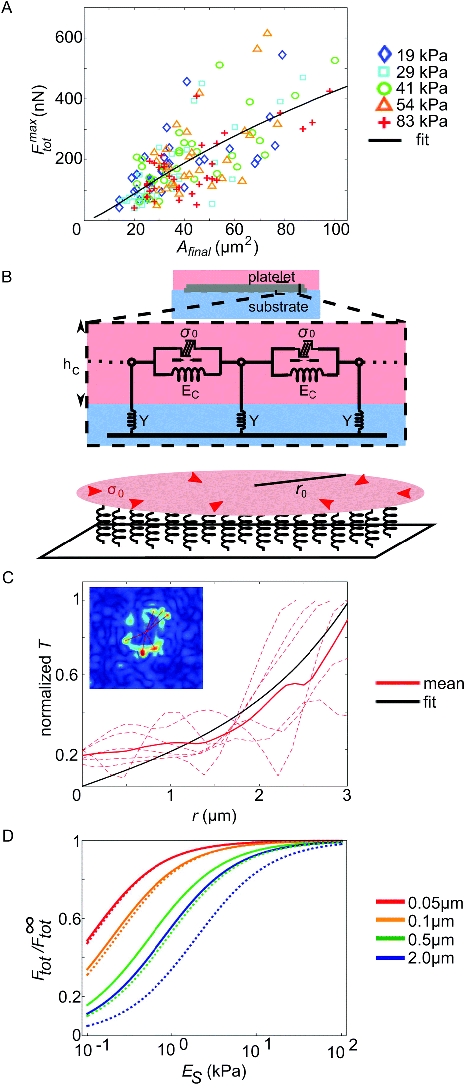 | ||
| Fig. 3 (A) Relation between the maximum total force and the final spread area for all evaluated platelets, color coded by substrate stiffness. The black line denotes the fit of our mathematical model (ESI,† eqn (S24)) to the data. (B) Cartoon of the model used for describing the dependence of the maximum total force on the cell spread area. (C) Analysis of the localization length by means of the traction stress data. (D) Effect of platelet thickness and the stiffness of cell–substrate adhesion bonds on the regime of substrate (ES) sensitivity. F∞tot is the maximum force the cell exerts on an infinitely rigid substrate. Solid lines correspond to an estimate for the stiffness of cell–substrate adhesion bonds based on (C), while dotted lines correspond to a threefold higher stiffness. The total cell force is an increasing function of the cell thickness (see ESI,† eqn (S25) and (S26)). | ||
In order to understand this relation between maximal stress and spread area, we introduce a mathematical model (see the model fit as a black line in Fig. 3A), in which we model a single platelet as an elastic disc of radius r0, height hc, elastic modulus Ec, and Poisson's ratio νc and with an isotropic and homogeneous contraction stress σ0 reflecting active cellular contractility,29 as sketched in Fig. 3B (a detailed description is found in the ESI,† part 5, including Table S2). We used r0 ≫ hc (thin film approximation) to emphasize the predominantly two-dimensional stress exertion of the platelets. The elastic disc is coupled to the underlying substrate using a spring stiffness density Y representing both the elasticity of the substrate and the focal adhesions. Consistent with our experiments, the calculated radial displacement field dr(r) and the corresponding radial tractions Tr(r) = Ydr(r) decay sharply near the cell periphery. This occurs on a length scale lL, the localization length29 that decreases with the cell–substrate adhesion density and with the cell and substrate stiffness, and is typically on the scale of a few microns (see eqn (S18) in the ESI†). Integrating over all radial tractions yields an analytical expression for the total force Ftot exerted by the contractile disc on the substrate. By fitting this expression to our experimental data, we estimate the values of two platelet characteristics, the mean localization length, lL = 1.8 μm, and the mean generated stress, σ0 = 162 kPa. While the former value is similar to other cellular systems, the latter points to a relatively high level of cell contractility. The total force is rescaled by the cell radius and plotted along with the corresponding fit in Fig. S7 (ESI†) as a function of the cell radius. This representation of the experimental data shows how the two parameters lL and σ0 govern the shape of the Ftot(r0) curve.
To further validate our estimate of a force correlation length around a few microns, we returned to the traction pattern of force hot spots shown in Fig. 1D–F and fitted exponentially decaying curves to the reconstructed traction patterns (shown for one example in Fig. 3C). The inset shows, in the red color, the lines along which we measured the traction profile. These traction profiles are shown as red dashed lines in the main plot. The full red line is the mean and the black curve is the model fit to the mean, yielding lL = 1.3 μm. This particular cell spreads to an area of 21 μm2 and reaches a force of 103 nN.
Interestingly, with this value for the force correlation length and the small value of the spread-platelet thickness, our model suggests that platelet mechanosensitivity should occur at stiffness values below the range investigated here: in Fig. 3D we plot the theoretical prediction of the force dependence on substrate stiffness ES for different values of the platelet thickness as denoted by different colors. To generate these plots, we used the values hc = 0.1 μm, Ec = 5 kPa and νc = 0.3 as typical estimates of the cell thickness,4 Young's modulus,10 and Poisson's ratio.47 The solid lines denote an adhesion layer stiffness density Naka = 0.3 nN μm−3 as estimated from our expression for the localization length in the ESI† for a rigid substrate; the dotted lines correspond to Naka = 1 nN μm−3. Comparing the dashed and solid lines we see that a softening of cell substrate adhesions (solid lines) shifts the substrate stiffness sensitivity regime to lower values. In both cases, however, with a typical platelet thickness of 0.1 μm and below we find no stiffness sensitivity above 1 kPa, in agreement with our experimental observations. For comparison, both endothelial cells48 and fibroblasts,49 both of which have been reported to be mechanosensitive in a stiffness regime above 1 kPa, exhibit such a small thickness only at the lamellipodial regions without myosin. In the myosin-rich lamellum and the perinuclear region, they display a much larger thickness in the range of 5 μm, in marked contrast to the platelets studied here.
3.4 The observed force field anisotropy is compatible with a random positioning of the force hot spots
Above we have focused on the spatial distribution of the force magnitudes and the temporal evolution of the total force Ftot(t). In order to investigate the force fields in more spatial detail we analyzed the major and minor force dipoles D1 and D2, respectively, and compared them to each other.50 Note that, due to noise, the dipole tensor determined directly from the traction force data is not in all cases symmetric. We only consider the symmetric part of the tensor as we assume the dipole axes to be perpendicular to each other. The average divergence over time from symmetry, i.e. the ratio between the symmetric and the skew-symmetric tensor, indeed is always less than 2.5% in the considered time interval. Fig. 4A shows an example for the two dipoles, overlaid with the traction force magnitude map (see Movie S2, ESI† for an animated version of this representation, including the outline of the cell at the last measured time point). When plotting the dipole amplitudes D1 and D2 against time, as shown in Fig. 4B (red and yellow curves) for one example, they typically proceed in parallel for the whole recording. The ratio of the dipole amplitudes, D1/D2, supports this conclusion. In this particular example, up to a recording time of 375 s after attachment, where no force is detected, the ratio is very noisy due to the small absolute values for D1 and D2. Thereafter, however, the temporal variance in D1/D2 drastically reduces and assumes a near constant value of about 1.5 (Fig. 4B, purple curve). Note that an isotropic contractile platelet would exhibit a dipole ratio of 1, with increasing values for higher degrees of anisotropy. For a statistical analysis of the ratio for all cells, we averaged this smooth region for each individual platelet. To do so, the variance Var(D1/D2) was determined within a moving frame of 17 data points. The first three variance values were taken as an estimate of the expected error in the calculation as in these frames, generally, no force is detected. To calculate the average dipole ratio, we included all values whose variance was equal or less than 10% of the expected error estimate. To ensure that the result is not dominated by noise, all values where the minor dipole falls below the norm of the skew-symmetric dipole tensor were excluded from the analysis. Fig. 4C shows box plots for the dipole ratios for the different substrate stiffnesses and a small, statistically not significant, trend towards higher anisotropy for higher stiffness. The average force anisotropy for all analyzed platelets is 2.5. Note that in Fig. 4C the median, not the average, is plotted.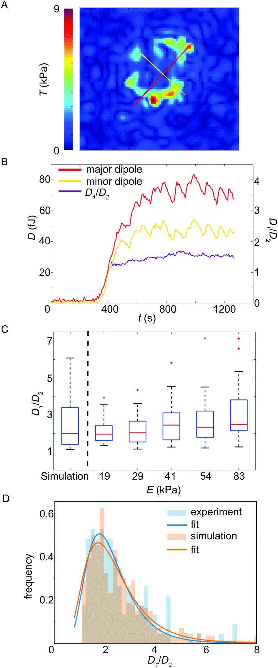 | ||
| Fig. 4 (A) Example showing the major (D1, red line) and minor (D2, yellow line) force dipoles, overlaid with the traction force magnitude map. (B) Temporal evolution of the major and minor dipole, respectively. In purple, we plot the ratio D1/D2 of the two dipoles. (C) Dipole ratio plotted against the substrate stiffness (simulation, left, and experiments, right). The simulation reproduces the experimental results well and we observe a slight trend towards stronger dipole anisotropy for stiffer substrates. The red line denotes the median and the lower and upper edges of the box correspond to the 25th and 75th percentiles, respectively. The whiskers show the distribution of all values not considering outliers (red crosses). (D) Histogram of experimentally observed dipole ratios and results of the corresponding simulations for 8 randomly (i.e. not necessarily symmetrically) positioned force hot spots on a circular line, each of which is directed towards the center of the image (see Fig. S8, ESI†). | ||
In order to test whether the observed force anisotropy of 2.5 is in agreement with a random distribution of force hot spots, as observed in the experimental data (see Fig. 1D–F), we performed a simulation of traction patterns as shown in Fig. S8 (ESI†). Fig. 4D shows histograms of the experimental and simulated dipole ratios and almost perfect agreement, supported by the box plot in Fig. 4C (left). Thus the observed anisotropy in the traction map is compatible with the experimentally observed random distribution of the force hot spots.
4 Discussion
Platelets challenge traditional TFM-routines because they are small and strong, while simultaneously showing very interesting dynamics when studying them for extended time periods. We present two approaches which are both based on FTTC, but deal with noise very differently (smoothing versus regularization). Importantly, because we were not able to use a first or last undeformed image as a reference image for each deformation image in the time series due to the large deformations occurring, here we have developed a differential approach in which each image is compared to the preceding one. Thus, we effectively calculate back to the very first reference image at t0. As a consequence, we are able to analyze large total bead displacements making our method applicable to cells that generate strong forces within short times as well as over longer observation times. Both specific algorithms extract the important biophysical results well from our data, that is, the spatio-temporal evolution of the force development and the distribution of the maxima in the force magnitude. Even the numeric values of the traction forces are very well comparable. Thus, our study also shows that implicit regularization by de-noising of the data is sufficient in this case (the smoothing-based algorithm), although a more rigorous treatment is given by explicit regularization (the regularization-based algorithm).51 In general, we find relatively high traction forces, with up to 10 kPa in the hot spots and a total force around 200 nN. We also note that the FTTC-procedures might underestimate the cell force scale, so the real forces might even be higher.22 In agreement with earlier work,31 we also found that platelets spread relatively quickly (within less than 10 minutes). Strikingly, force generation sets in later and takes longer (30 minutes). These findings are in good agreement with our recent work where we tracked the temporal evolution of the actin cytoskeleton in living platelets, using SiR-actin as a probe.52 We observed actin polymerization-driven spreading on a time scale of one minute after adhesion and a rapid build-up of stress-fiber-like actin bundles on a time scale of four mins, which are enforced thereafter. Similarly, in the recent paper by Wang et al.,13 a low-tension regime in platelets was reported, starting directly after adhesion at the cell periphery. After four mins, a high-tension regime was observed, focused at two to three spots at the periphery. Thus, we conclude that directly after adhesion, only very low polymerization forces occur, which are not sufficient to deform the substrate. At a later stage, when defined actin bundles are built up, the acto-myosin interaction creates higher forces, concentrated in hot spots, as described here.Based on these direct measurements of the total force and the corresponding model estimate of the generated internal stress, which turns out to be hundreds of kPa, we conclude that platelets exert comparatively large forces despite their small size and extremely small thickness. The question remains why the force levels we measure here are almost one order of magnitude higher than the results presented by Lam et al.10 and in our own previous work.11 One important difference to the work described in ref. 10, as already argued before,11 is the geometry of the experimental set-up. We consider the contraction of the platelets on a two-dimensional substrate, whereas Lam et al. pulled vertically by AFM. Thus, horizontal contractions could be underestimated or missing entirely in the measurement. Additionally, the higher concentration of thrombin used here could play an important role. Still, we observe higher forces than the previous TFM approach, where softer gels (4 kPa) were used.11 It cannot be ruled out that these very soft gels were deformed in three dimensions during the experiments and the z-information is missing in the analysis, as reported previously.53 Furthermore, in ref. 11, direct particle tracking was conducted on images of 100 nm-sized beads with around 300 individual beads for one cell including its nearest neighbourhood. Here we work with higher bead densities, with about 6000 beads on an equivalent area, and thus reach a considerably increased resolution. We therefore assume that the reduced spatial resolution in our earlier work has resulted in a loss of information. In the future, it might be interesting to further improve the resolution, e.g. by using super-resolution microscopy.54 Physiologically, the high forces might be useful for efficiently contracting (large) blood clots in order to restore blood flow quickly and reliably.
Surprisingly, our work does not show mechanosensitivity in the studied range of stiffnesses (19 to 83 kPa), in contrast to the AFM study by Lam et al.,10 who did observe a rigidity dependence between 12 kPa, 29 kPa and an infinitely stiff environment. Similarly, Qui et al. reported that after 2 hours incubation time more platelets spread on stiffer substrates as well as to a larger area than for soft substrates.14 It should be noted, however, that these two studies used thrombin at a lower concentration than us, or not at all, which likely leads to lower generated forces in general.9 Furthermore, substrate and cantilever coating with fibrinogen was performed at comparatively low concentrations (3 and 20 μg mL−1, respectively). Very interestingly, Qui et al. observed that the effect on the platelet spread area, as well as, between 5 and 100 kPa, the effect on the number of adhered platelets, vanishes at a fibrinogen concentration of 100 μg mL−1, which corresponds to what we have used here. This dependence on the ligand density is in agreement with previous work.55 In future work it will be interesting to systematically study the influence of the ligand density on force generation, as well as different pre-activation levels using thrombin at different concentrations. We thus conclude that one possible explanation for the lack of mechanosensitivity in our work is the higher level of activation by thrombin and fibrinogen.
Furthermore, using typical estimates of platelet stiffness and thickness, we have demonstrated in Fig. 3D that the regime of substrate stiffness sensitivity of cells with platelet dimensions is likely to fall in the kPa regime and below for the flat substrate geometry studied here. Thus, supported by our model, we speculate that the uniquely small thickness of the platelets effectively softens these cells and shifts their stiffness sensitivity regime to lower values.
The time scales we observe for the force development are on the order of 10–30 min, which is considerably slower than platelet spreading, which is on the order of few mins. Thus while there is a period where the cell area and force increase simultaneously, the continued evolution of the platelet force at longer times is likely to reflect internal force generation processes not related to changes in cell size. Most likely these forces correspond rather to actomyosin contractility than to actin polymerization. As a rough estimate of the expected force generated by acto-myosin, we assume an average of about 12![[thin space (1/6-em)]](https://www.rsc.org/images/entities/char_2009.gif) 000 single myosin II motors in each cell,1 which generate up to 10 pN each.56 This sets an upper bound of about 120 nN, and thus exactly on the same order of magnitude as our measured data, which yield an average maximum force of 186 nN. This result is in agreement with the strong activation with a high thrombin concentration in our experiments.9 It should be noted that we pre-selected those platelets for analysis that spread and contracted within our calculation error bound. This led to a group of cells with an average spread area of about 40 μm2, slightly higher than the previously reported spread area.30 Thus, it is very well possible that the average number of myosin motors per cell may be higher in our experiments than determined from large platelet ensembles in ref. 1.
000 single myosin II motors in each cell,1 which generate up to 10 pN each.56 This sets an upper bound of about 120 nN, and thus exactly on the same order of magnitude as our measured data, which yield an average maximum force of 186 nN. This result is in agreement with the strong activation with a high thrombin concentration in our experiments.9 It should be noted that we pre-selected those platelets for analysis that spread and contracted within our calculation error bound. This led to a group of cells with an average spread area of about 40 μm2, slightly higher than the previously reported spread area.30 Thus, it is very well possible that the average number of myosin motors per cell may be higher in our experiments than determined from large platelet ensembles in ref. 1.
Our TFM-results as well as our mathematical model suggest that tractions are mainly localized at the cell periphery, in agreement also with two recent studies using force biosensors.12,13 Interestingly, we observe force hot spots that can explain the anisotropy in the traction patterns. As shown earlier both theoretically and experimentally for other cell types, the force anisotropy of cells may partially be induced by the cells' anisotropic shape, particularly if the aspect ratio of the cells is large.57,58 Although the present recordings of the shape of the cell membrane are too low in image contrast for a detailed and quantitative shape analysis (see Movies S3 and S4, ESI†), we estimated the shape anisotropy for each platelet after complete spreading to be around 1.2, which is too small to explain the force anisotropy of D1/D2 ≈ 2.5. Moreover when comparing the shape anisotropy to the force dipole ratio for each individual cell, we do not find a correlation. Thus we conclude that the measured force anisotropy is not a result of the shape anisotropy, but more likely reflects the internal organization leading to the force hot spots. From studying the actin structure of spread and fixed platelets on PAA gels (Fig. 1D–F, right) or polystyrene culture dishes,59 we know that different actin patterns occur and they often display stress fibre-like structures. The end-points of these extended structures may coincide with the force maxima observed in the force fields (see Fig. 1D–F, left).
A question remains concerning the origin of the oscillatory behavior exhibited by some of the studied platelets. Using scanning ion conductance microscopy, the authors of ref. 59 observed wave-like movement of the membrane around the platelet periphery upon stimulation with thrombin. Our membrane imaging resolution does not allow for a similarly detailed quantitative analysis. We can, however, speculate that the two phenomena are related, possibly through calcium dynamics, as these oscillations show a similar frequency spectrum.
5 Conclusions
Using adapted TFM-methods that reconstruct traction force in an iterative way image by image and thus work for extended periods of time and large substrate deformations, we studied the dynamics of force generation in platelets. These cells are very small (40 μm2 average final spread area), very strong (forces up to 600 nN) and very dynamic (including oscillations with a frequency in the range 10–15 mHz). Consequently, established TFM-algorithms fail to capture the process in space and time. Within the stiffness range between 19 and 83 kPa, the total force showed no clear dependence on the substrate stiffness, possibly because the platelets were fully activated. A mathematical model demonstrates very high intracellular stress levels and moreover suggests that platelets are too thin to feel rigidity differences in this range. The observed oscillations and anisotropies in force generation point to an intracellular level of organization that has not yet been revealed. Future experiments, directly combining high-resolution imaging with force measurements may help to elucidate this open question. Furthermore, a systematic study of varying concentration of thrombin in solution and surface-attached fibrinogen is likely to shed light on their impact on platelet mechanosensitivity. A variation of substrate stiffness towards softer gels, below 10 kPa, would be necessary for validating our model predictions in Fig. 3D which pertain to the regime of substrate stiffness sensitivity. The temporal sequence of force generating mechanisms, i.e. actin polymerization and acto-myosin action, requires controlled addition of blebbistatin before spreading begins, albeit after the microtubule marginal band of the platelets has been destroyed, as an intact microtubule ring stabilizes platelets and inhibits spreading. Such an experiment could be designed with microfluidics methods.Taking the application of our experimental set-up and model-based analysis methods a step further towards more physiologically relevant environments, the development of clots (starting from the interaction of two or very few individual platelets) and the corresponding traction forces could be studied. As mentioned previously, it is not yet clear if all platelets within a clot actively contribute to the exerted force and how. Hence, by studying the number of platelets within a clot, their time points of attachment and the dynamics of their forces, this question can be addressed. Additionally, it would be very interesting to study cooperativity within groups of platelets, both in terms of spatial organization and force generation.
Conflicts of interest
There are no conflicts to declare.Acknowledgements
We thank Aishwarya Paknikar, Anna Zelena and Tim Dullweber for technical help and Alexander Strate, Tobias Legler and Joachim Riggert for providing platelet concentrates and for many fruitful discussions. This work was funded by the German Research Foundation (DFG) in the framework of SFB 937, project A12 (S. K.). U. S. S. is a member of the cluster of excellence CellNetworks and of the Interdisciplinary Center for Scientific Computing (IWR) at Heidelberg. D. P. was supported by Landesgraduiertenförderung Baden-Württemberg.Notes and references
- A. D. Michelson, Platelets, Elsevier/Academic Press, Amsterdam and London, 2nd edn, 2007 Search PubMed.
- B. Diagouraga, A. Grichine, A. Fertin, J. Wang, S. Khochbin and K. Sadoul, J. Cell Biol., 2014, 204, 177–185 CrossRef PubMed.
- S. Dmitrieff, A. Alsina, A. Mathur and F. J. Nédélec, Proc. Natl. Acad. Sci. U. S. A., 2017, 114, 4418–4423 CrossRef PubMed.
- D. Aquino, A. Schönle, C. Geisler, C. V. Middendorff, C. A. Wurm, Y. Okamura, T. Lang, S. W. Hell and A. Egner, Nat. Methods, 2011, 8, 353–359 CrossRef PubMed.
- M. E. Carr, Cell Biochem. Biophys., 2003, 38, 55–78 CrossRef PubMed.
- C. J. Jen and L. V. McIntire, Cell Motil., 1982, 2, 445–455 CrossRef PubMed.
- C. Léon, A. Eckly, B. Hechler, B. Aleil, M. Freund, C. Ravanat, M. Jourdain, C. Nonne, J. Weber, R. Tiedt, M.-P. Gratacap, S. Severin, J.-P. Cazenave, F. Lanza, R. Skoda and C. Gachet, Blood, 2007, 110, 3183–3191 CrossRef PubMed.
- M. E. Carr and S. L. Zekert, Am. J. Med. Sci., 1991, 302, 13–18 CrossRef PubMed.
- X. M. Liang, S. J. Han, J.-A. Reems, D. Gao and N. J. Sniadecki, Lab Chip, 2010, 10, 991 RSC.
- W. A. Lam, O. Chaudhuri, A. Crow, K. D. Webster, T.-D. Li, A. Kita, J. Huang and D. A. Fletcher, Nat. Mater., 2010, 10, 61–66 CrossRef PubMed.
- S. Schwarz Henriques, R. Sandmann, A. Strate and S. Köster, J. Cell Sci., 2012, 125, 3914–3920 CrossRef PubMed.
- Y. Zhang, Y. Qiu, A. T. Blanchard, Y. Chang, J. M. Brockman, V. P.-Y. Ma, W. A. Lam and K. Salaita, Proc. Natl. Acad. Sci. U. S. A., 2018, 115, 325–330 CrossRef PubMed.
- Y. Wang, D. N. LeVine, M. Gannon, Y. Zhao, A. Sarkar, B. Hoch and X. Wang, Biosens. Bioelectron., 2018, 100, 192–200 CrossRef PubMed.
- Y. Qiu, A. C. Brown, D. R. Myers, Y. Sakurai, R. G. Mannino, R. Tran, B. Ahn, E. T. Hardy, M. F. Kee, S. Kumar, G. Bao, T. H. Barker and W. A. Lam, Proc. Natl. Acad. Sci. U. S. A., 2014, 111, 14430–14435 CrossRef PubMed.
- N. Nisenholz, K. Rajendran, Q. Dang, H. Chen, R. Kemkemer, R. Krishnan and A. Zemel, Soft Matter, 2014, 10, 7234 RSC.
- A. Engler, L. Bacakova, C. Newman, A. Hategan, M. Griffin and D. Discher, Biophys. J., 2004, 86, 617–628 CrossRef PubMed.
- M. Dembo and Y.-L. Wang, Biophys. J., 1999, 76, 2307–2316 CrossRef PubMed.
- A. J. Engler, S. Sen, H. L. Sweeney and D. E. Discher, Cell, 2006, 126, 677–689 CrossRef PubMed.
- R. W. Style, R. Boltyanskiy, G. K. German, C. Hyland, C. W. MacMinn, A. F. Mertz, L. A. Wilen, Y. Xu and E. R. Dufresne, Soft Matter, 2014, 10, 4047–4055 RSC.
- U. S. Schwarz and J. R. Soiné, Biochim. Biophys. Acta, Mol. Cell Res., 2015, 1853, 3095–3104 CrossRef PubMed.
- P. Roca-Cusachs, V. Conte and X. Trepat, Nat. Cell Biol., 2017, 19, 742–751 CrossRef PubMed.
- J. R. D. Soiné, C. A. Brand, J. Stricker, P. W. Oakes, M. L. Gardel and U. S. Schwarz, PLoS Comput. Biol., 2015, 11, e1004076 CrossRef PubMed.
- J. P. Butler, I. M. Tolic-Norrelykke, B. Fabry and J. J. Fredberg, Am. J. Physiol.: Cell Physiol., 2002, 282, C595–C605 CrossRef PubMed.
- H. Delanoë-Ayari, S. Iwaya, Y. T. Maeda, J. Inose, C. Rivière, M. Sano and J.-P. Rieu, Cell Motil. Cytoskeleton, 2008, 65, 314–331 CrossRef PubMed.
- S. Munevar, Y.-L. Wang and M. Dembo, Biophys. J., 2001, 80, 1744–1757 CrossRef PubMed.
- Y. Aratyn-Schaus, P. W. Oakes and M. L. Gardel, Mol. Biol. Cell, 2011, 22, 1330–1339 CrossRef PubMed.
- K. L. Hui, L. Balagopalan, L. E. Samelson and A. Upadhyaya, Mol. Biol. Cell, 2015, 26, 685–695 CrossRef PubMed.
- A. F. Mertz, S. Banerjee, Y. Che, G. K. German, Y. Xu, C. Hyland, M. C. Marchetti, V. Horsley and E. R. Dufresne, Phys. Rev. Lett., 2012, 108, 198101 CrossRef PubMed.
- C. M. Edwards and U. S. Schwarz, Phys. Rev. Lett., 2011, 107, 128101 CrossRef PubMed.
- R. Sandmann, S. Schwarz Henriques, F. Rehfeldt and S. Köster, Soft Matter, 2014, 10, 2365–2371 RSC.
- R. Sandmann and S. Köster, Sci. Rep., 2016, 6, 22357 CrossRef PubMed.
- V. Leytin, D. J. Allen, E. Lyubimov and J. Freedman, Br. J. Haematol., 2007, 136, 762–764 CrossRef PubMed.
- B. Sabass, M. L. Gardel, C. M. Waterman and U. S. Schwarz, Biophys. J., 2008, 94, 207–220 CrossRef PubMed.
- M. Raffel, C. E. Willert and J. Kompenhans, Particle image velocimetry: A practical guide, Springer, Berlin and London, 1998 Search PubMed.
- P. W. Oakes, S. Banerjee, M. C. Marchetti and M. L. Gardel, Biophys. J., 2014, 107, 825–833 CrossRef PubMed.
- A. I. Ruban and J. S. B. Gajjar, Fluid Dynamics, Oxford University Press, 2014 Search PubMed.
- S. V. Plotnikov, B. Sabass, U. S. Schwarz and C. M. Waterman, Methods Cell Biol., 2014, 123, 367–394 Search PubMed.
- C. Tomasi and T. Kanade, Detection and Tracking of Point Features, Technical Report CMU-CS-91-132, Carnegie Mellon University, 1991 Search PubMed.
- J. Shi and C. Tomasi, IEEE Conference on Computer Vision and Pattern Recognition, 1994, pp. 593–600 Search PubMed.
- B. D. Lucas and T. Kanade, Intl. Joint Conf. on Artificial Intelligence, Vancouver, British Columbia, 1981 Search PubMed.
- J.-Y. Bouguet, Intel Corporation, 2001, 5, 1–9 Search PubMed.
- J. W. Tukey, An introduction to the calculations of numerical spectrum analysis, Wiley, New York, 1967 Search PubMed.
- M. A. Lukas, Inverse Probl. Sci. Eng., 2008, 24, 034006 CrossRef.
- J. P. Califano and C. A. Reinhart-King, Cell. Mol. Bioeng., 2010, 3, 68–75 CrossRef PubMed.
- C. N. Holenstein, U. Silvan and J. G. Snedeker, Sci. Rep., 2017, 7, 41633 CrossRef PubMed.
- S. J. Han, K. S. Bielawski, L. H. Ting, M. L. Rodriguez and N. J. Sniadecki, Biophys. J., 2012, 103, 640–648 CrossRef PubMed.
- W. R. Trickey, F. P. T. Baaijens, T. A. Laursen, L. G. Alexopoulos and F. Guilak, J. Biomech., 2006, 39, 78–87 CrossRef PubMed.
- D. T. Tambe, C. C. Hardin, T. E. Angelini, K. Rajendran, C. Y. Park, X. Serra-Picamal, E. H. Zhou, M. H. Zaman, J. P. Butler, D. A. Weitz, J. J. Fredberg and X. Trepat, Nat. Mater., 2011, 10, 469–475 CrossRef PubMed.
- C. Bottier, C. Gabella, B. Vianay, L. Buscemi, I. F. Sbalzarini, J.-J. Meister and A. B. Verkhovsky, Lab Chip, 2011, 11, 3855–3863 RSC.
- U. S. Schwarz and S. A. Safran, Phys. Rev. Lett., 2002, 88, 048102 CrossRef PubMed.
- U. S. Schwarz, N. Q. Balaban, D. Riveline, A. Bershadsky, B. Geiger and S. A. Safran, Biophys. J., 2002, 83, 1380–1394 CrossRef PubMed.
- A. K. Paknikar, B. Eltzner and S. Köster, Prog. Biophys. Mol. Biol., 2018 DOI:10.10167/j.pbiomolbio.2018.05.001.
- H. Delanoë-Ayari, J. P. Rieu and M. Sano, Phys. Rev. Lett., 2010, 105, 248103 CrossRef PubMed.
- H. Colin-York, D. Shrestha, J. H. Felce, D. Waithe, E. Moeendarbary, S. J. Davis, C. Eggeling and M. Fritzsche, Nano Lett., 2016, 16, 2633–2638 CrossRef PubMed.
- M. Jirousková, J. K. Jaiswal and B. S. Coller, Blood, 2007, 109, 5260–5269 CrossRef PubMed.
- A. Knight, Single molecule biology, Elsevier Academic Press, London, 2009 Search PubMed.
- N. Nisenholz, M. Botton and A. Zemel, Soft Matter, 2014, 10, 2453–2462 RSC.
- A. Zemel, F. Rehfeldt, A. E. X. Brown, D. E. Discher and S. A. Safran, Nat. Phys., 2010, 6, 468–473 Search PubMed.
- J. Seifert, J. Rheinlaender, F. Lang, M. Gawaz and T. E. Schäffer, Sci. Rep., 2017, 7, 4810 Search PubMed.
Footnotes |
| † Electronic supplementary information (ESI) available. See DOI: 10.1039/c8sm00895g |
| ‡ These authors contributed equally to the work. |
| This journal is © The Royal Society of Chemistry 2018 |