
Powder-based (CuGa1−yIny)1−xZn2xS2 solid solution photocathodes with a largely positive onset potential for solar water splitting†
Toshio
Hayashi
ab,
Ryo
Niishiro
ab,
Hitoshi
Ishihara
a,
Masaharu
Yamaguchi
c,
Qingxin
Jia
c,
Yongbo
Kuang
c,
Tomohiro
Higashi
c,
Akihide
Iwase
 d,
Tsutomu
Minegishi
c,
Taro
Yamada
c,
Kazunari
Domen
c and
Akihiko
Kudo
*d
d,
Tsutomu
Minegishi
c,
Taro
Yamada
c,
Kazunari
Domen
c and
Akihiko
Kudo
*d
aJapan Technological Research Association of Artificial Photosynthetic Chemical Process (ARPChem), 7-3-1 Hongo, Bunkyo-ku, Tokyo 113-8656, Japan
bMitsui Chemicals, Inc., 580-32 Nagaura, Sodegaura, 299-0265 Chiba, Japan
cDepartment of Chemical System Engineering, The University of Tokyo, 7-3-1 Hongo, Bunkyo-ku, Tokyo 113-8656, Japan
dDepartment of Applied Chemistry, Faculty of Science, Tokyo University of Science, 1-3 Kagurazaka, Shinjuku-ku, Tokyo 162-8601, Japan. E-mail: a-kudo@rs.kagu.tus.ac.jp
First published on 23rd March 2018
Abstract
Photoelectrochemical water splitting has attracted much attention in recent years as an alternative energy source. However, there have been several significant issues such as low efficiency, high cost and less scalability for its practical application. Here, we show that (CuGa1−yIny)1−xZn2xS2 (CGIZS)-based photocathodes fabricated with a particle transfer method exhibited a photocurrent of 4.5 mA cm−2 at 0.6 V vs. RHE along with a largely positive onset potential of 1.0 V vs. RHE under simulated sunlight (AM 1.5G) and an initial solar-to-hydrogen energy conversion efficiency of 1.1% was obtained with photoelectrochemical water splitting using a two-electrode cell composed of the CGIZS-based photocathode and a BiVO4-based photoanode. CGIZS used for the particle transfer method was obtained in a powder state with high crystallinity by a flux method using a molten-salt of LiCl–KCl, and also formed solid solutions with a chalcopyrite single phase structure in a wide range of Ga/In ratios and Zn contents, in which the absorption edges of photocatalysts were tunable up to 880 nm.
Introduction
Solar water splitting which can directly convert solar energy to chemical energy has been regarded as one of the most promising environmentally friendly technologies in the near future.1,2 Photoelectrochemical (PEC) hydrogen production using photo-semiconductors has been extensively studied so far.3–5 High stability, low cost, and scalability as well as a high solar-to-hydrogen energy conversion efficiency (STH) are essential for its practical application.6 In the combined system of a photocathode and a photoanode for PEC water splitting, the current–potential curve in each cathodic or anodic photocurrent has to intersect each other at a certain electrode potential when the combined photoelectrochemical cell functions for water splitting under no bias conditions. Therefore, it is important that the onset potential should be more positive for the photocathode and more negative for the photoanode. The onset potentials of the photocathode and the photoanode are theoretically predominated by Fermi energies close to the VBM (valence band maximum) and CBM (conduction band minimum), respectively.Copper-containing sulfide materials possessing a relatively positive VBM which consists of a hybrid orbital with Cu 3d and S 3p can be expected to lead to a more positive onset potential compared to copper-containing selenide materials such as conventional CIGS (Cu–In–Ga–Se) which gives a higher current density but a relatively negative onset potential of 0.7 V vs. RHE.7 As a selenide material, Cu(In,Ga)Se2–ZnSe solid solutions particularly show a relatively positive onset potential of 0.89 V vs. RHE as well as a high photocurrent density of 7.1 mA cm−2 at 0 V vs. RHE, when a photoelectrode is prepared by a vacuum co-evaporation process.8 Considering the practical use, the use of powder is favorable for fabricating large-scale photoelectrodes. However, the powder-based Cu(In,Ga)Se2–ZnSe photocathode shows a lower photoelectrochemical performance with a photocurrent of 4.3 mA cm−2 at 0 V vs. RHE and an onset potential of 0.8 V vs. RHE than the photocathode prepared by the vacuum co-evaporation process.9 Thus, the development of powder-based photocathodes with high electrochemical performance is an important issue to fabricate highly efficient photoelectrochemical cells.
Many sulfide materials, especially, copper-containing sulfides, have been reported as excellent photocatalysts and photoelectrodes due to p-type conductivity, visible light absorption, facile formation of solid solutions and low toxicity.10–14 We have also developed novel sulfide photocatalysts containing copper such as a CuInS2–ZnS solid solution,15 CuGa2In2S8 (ref. 16) and a CuGaS2–ZnS solid solution17 with which PEC water splitting into H2 and O2 under simulated sunlight was demonstrated by combining them with a BiVO4 photoanode. In particular, solid solutions with ZnS often lead to high photocatalytic performance. Therefore, (CuGa1−yIny)1−xZn2xS2 (CGIZS), the solid solution between Cu(Ga1−yIny)S2 and ZnS, will be an interesting material as a photocathode for PEC water splitting because the VBM and CBM can be controlled by changing x and y of the ratios.
A flux method at a relatively low melting-point can be expected to provide micrometer-sized highly crystalline powder compared with solid-state synthesis.18,19 A particle transfer method20,21 is facile and suitable for an effective formation of photocatalyst powder monolayers and a better contact with the substrate electrode using powdered photocatalysts. In addition, it is also of great interest in terms of cost reduction that particulate CGIZS photoelectrodes can be fabricated through a facile non-vacuum deposition technique such as spray coating, screen printing, ink-jet printing, squeegee, and electrophoretic deposition.
In the present study, micrometer-sized CGIZS crystalline powder grown from chloride-based fluxes was prepared for the particle transfer fabrication of photocathodes. The effects of the composition of CGIZS and the surface modification with CdS, TiO2, and Pt on the photoelectrochemical performance were investigated. The CGIZS powder-based photocathode showed a largely positive onset potential and a high current density, leading to excellent performance in PEC solar water splitting.
Experimental
Preparation of the Cu0.8Ga0.4In0.4Zn0.4S2 (CGIZS) photocatalyst powder by a flux method
Starting materials of Cu2S (High Purity Chemicals; 99%), Ga2S3 (High Purity Chemicals; 99.99%), In2S3 (High Purity Chemicals; 99.99%), and ZnS (High Purity Chemicals; 99.999%) were mixed well using an agate mortar in a molar ratio of Cu2S/Ga2S3/In2S3/ZnS = 0.80![[thin space (1/6-em)]](https://www.rsc.org/images/entities/char_2009.gif) :0.40:0.40:0.80 in a N2 atmosphere. 20–30 mol% of excess Ga2S3 was added. A flux treatment was carried out normally by immersing the mixture of starting materials in a mixture of molten LiCl (Kanto Chemical; 99.0%) and KCl (Kanto Chemical; 99.5%) in a molar ratio of LiCl/KCl = 3:2 (melting point; 625 K) at 723–1123 K for 3–25 h in a quartz tube under vacuum conditions. After cooling to room temperature, the obtained sample was washed with pure water using suction filtration to remove the LiCl–KCl flux, and then dried at 313 K for 1 day in vacuo. (CuGa1−yIny)1−xZn2xS2 photocatalyst powders with different compositions were prepared in a similar manner to the Cu0.8Ga0.4In0.4Zn0.4S2 (x = 0.2, y = 0.5) photocatalyst powder.
:0.40:0.40:0.80 in a N2 atmosphere. 20–30 mol% of excess Ga2S3 was added. A flux treatment was carried out normally by immersing the mixture of starting materials in a mixture of molten LiCl (Kanto Chemical; 99.0%) and KCl (Kanto Chemical; 99.5%) in a molar ratio of LiCl/KCl = 3:2 (melting point; 625 K) at 723–1123 K for 3–25 h in a quartz tube under vacuum conditions. After cooling to room temperature, the obtained sample was washed with pure water using suction filtration to remove the LiCl–KCl flux, and then dried at 313 K for 1 day in vacuo. (CuGa1−yIny)1−xZn2xS2 photocatalyst powders with different compositions were prepared in a similar manner to the Cu0.8Ga0.4In0.4Zn0.4S2 (x = 0.2, y = 0.5) photocatalyst powder.
Preparation of CGIZS photoelectrodes by a particle transfer method
CGIZS photocatalyst particles were deposited onto a primary glass substrate by drop-casting CGIZS particles dispersed in isopropanol. An Au contact layer was deposited onto the CGIZS particle layer by vacuum evaporation. The layers (Au/CGIZS) were bonded to the second glass substrate with a carbon tape, and then peeled off the primary glass substrate. After removing the excess CGIZS particles using ultrasonication in pure water, the CGIZS photoelectrode (CGIZS/Au/glass) was obtained. A Cu wire was connected onto the contact and conducting layers using In solder. The unnecessary part was completely covered with an epoxy resin.Surface modifications of CGIZS photoelectrodes with CdS, TiO2, and Pt
A CdS layer was deposited by chemical bath deposition. The CGIZS photoelectrode was immersed at 343 K for 30 min in 50 mL of an aqueous solution containing Cd(CH3COO)2·2H2O (Kanto Chemical; 98.0%), SC(NH2)2 (Wako Pure Chemical; 98.0%) and ammonia at concentrations of 0.025 mol L−1, 0.375 mol L−1, and 1.5 mol L−1, respectively. After the chemical bath deposition, the obtained photoelectrodes were washed with pure water, and then dried at room temperature in air. If necessary, a TiO2 layer was formed on the CdS-modified CGIZS (CdS/CGIZS/Au) photoelectrodes by dropwise addition of an aqueous solution mixed with 30% hydrogen peroxide solution (1 μL), titanium tetraisopropoxide (25 μL), and water (4 mL). A Pt cocatalyst was deposited onto the CdS/CGIZS/Au and TiO2-modified CdS/CGIZS/Au photoelectrodes using a magnetron sputtering machine (Shinku Device; MSP-30T).Characterization of photocatalysts and photoelectrodes
Crystal phases of the obtained powders were confirmed using X-ray diffraction (Rigaku; SmartLab, Cu Kα). The X-ray diffraction (XRD) patterns were collected from 5° to 70° (2θ) using a step size of 0.02°. The source power and current of Cu Kα radiation were 40 kV and 30 mA, respectively. Diffuse reflection spectra (DRS) were obtained using a UV-VIS-NIR spectrometer (JASCO; V-670) and were converted from reflectance to absorbance by the Kubelka–Munk method. Photocatalyst powders and photoelectrodes were observed using a scanning electron microscope (Hitachi High-Technologies; SU8020) and a field emission transmission electron microscope (JEOL; JEM-2200FS). Elemental analysis was performed using an energy dispersive X-ray spectrometer (Bruker; QUANTAX FlatQuad). Photoelectrodes were cut using a focused ion beam (SEIKO Instruments; SMI2050) for the cross-sectional observation. The ionization potentials of powdered photocatalyst samples were analyzed by photoelectron spectroscopy in air (PESA; AC-3, Riken Keiki) in the range of 4.0–7.0 eV using a Xe lamp.Photoelectrochemical measurements
Photoelectrochemical measurements were carried out using a three-electrode system composed of the CGIZS working electrode, a Pt counter electrode, and an Ag/AgCl reference electrode (TOYO; TRE-10) with a potentiostat (HOKUTO DENKO; HSV-110 or HZ-7000) under an Ar atmosphere in a one-pot type cell. An aqueous phosphate buffer solution (0.5 mol L−1 of Na2SO4 (Wako Pure Chemical; 99.0%) + 0.25 mol L−1 of NaH2PO4 (Wako Pure Chemical; 99.0%) + 0.25 mol L−1 of Na2HPO4 (Kanto Chemical; 99.0%)) with pH 7.0 was used as a standard electrolyte. A solar simulator (SAN-EI ELECTRIC; XES-40S1) producing AM 1.5G simulated sunlight was used as a light source. In the current–potential measurements, the applied potential was swept at 20 mV s−1 from 0 V vs. RHE under intermittent irradiation of simulated sunlight for a period of 2 s. The activation of the CGIZS cathode before use was ordinarily done by performing cyclic voltammetry between 0.0 and 1.0 V vs. RHE for 5–20 cycles at a scan rate of 20 mV s−1 in the same aqueous phosphate buffer solution (pH 6.4) under AM 1.5G irradiation. The typical j–V curves in the activation process are shown in Fig. S1.†Incident photon-to-current conversion efficiency (IPCE) measurements were carried out using a 300 W Xe lamp (Asahi Spectra; MAX-302) with a band-pass filter (Asahi Spectra; MX0420-0800) for monochromatic light irradiation. A photodiode (OPHIR; PD300-UV-SH head and NOVA II display) was used for the measurement of the number of incident photons.
Photoelectrochemical solar water splitting was carried out using a two-electrode system composed of the CGIZS and BiVO4 photoelectrodes (Fig. S2†). The aqueous phosphate solution as mentioned above was used as the electrolyte in which pH was adjusted by using an aqueous KOH solution. The amounts of evolved gases were determined by the use of on-line gas chromatography (Shimadzu; GC-8A, MS-5A column, TCD, Ar carrier). The ordinary activation of the CGIZS cathode before use was done for 5 cycles at least and the activated CGIZS cathode was rinsed with pure water and stored in air for usage.
Preparation of BiVO4 photoelectrodes
The nanoworm BiVO4 electrodes were synthesized according to a previously reported method.22,23 Because Ni-based catalysts dissolve very fast in neutral or near-neutral phosphate electrolytes,6 a CoFe-based oxygen evolving catalyst (CoFeOx) modification was developed so as to deliver a better stability in such solutions. First, Co(OH)2 was cathodically deposited over the BiVO4 surface at −0.75 V vs. Ag/AgCl for 15 seconds in a 0.1 mol L−1 Co(NO3)2 solution using a three-electrode configuration. The as-deposited electrode was thoroughly washed with pure water and was then put into a 1 mol L−1 potassium borate solution (pH 9) and exposed to AM 1.5G irradiation for 30 seconds at 0.6 V vs. RHE, immediately followed by immersion into a 0.01 mol L−1 FeSO4 solution for 30 seconds after a quick rinse with deionized water. The final activation was done by performing cyclic voltammetry between 0.1 and 1.3 V vs. RHE for 4 cycles at a scan rate of 40 mV s−1 in a 1 mol L−1 potassium borate solution under AM1.5 irradiation. The activated CoFeOx/BiVO4 was rinsed with deionized water and stored in air for usage. The detailed study of this catalyst modification method will be discussed in a separate report.Calculations
E Ag/AgCl was converted to ERHE according the following equation.| [ERHE/V] = [EAg/AgCl/V] + 0.199 + 0.059 × [pH] |
IPCE was determined by the following equation.
| [IPCE%] = 100 × [j/mA cm−2] × 1240/([Pmono/mW cm−2] × [λ/nm]) |
| [STH%] = 100 × [I/mA] × [1.23/V]/([PSUN/mW cm−2] × [S/cm2]) |
Results and discussion
Preparation and characterization of the (CuGa1−yIny)1−xZn2xS2 (CGIZS) solid solution powder
Fig. 1a shows the X-ray diffraction (XRD) patterns of typical (CuGa1−yIny)1−xZn2xS2 photocatalysts (x/y = 0.2/0.0, 0.2/0.5, 0.2/0.75, 0.2/1.0, 0.0/0.5, 0.4/0.5, 0.6/0.5 and Ga 20% excess) prepared by the flux method at 823 K for 15 h, indicating that the single phases of chalcopyrite structures were successfully obtained in the ranges of y = 0–1.0 (x = 0.2) and x = 0–1.0 (y = 0.5), in which the case of x = 1.0 corresponded to ZnS. In the (CuGa1−yIny)0.8Zn0.4S2 (x = 0.2), the diffraction peaks shifted to the low-angle side as the value of y increased, i.e. the In content increases while the Ga content decreases. The shift was reasonable because the ion radius of In3+ (0.62 Å) was larger than that of Ga3+ (0.47 Å). The cell volumes of CGIZS photocatalysts as a function of x and y showed a linear relationship according to Vegard's law (Fig. 1b and c). Thus, we confirmed that CGIZS solid solutions with the same chalcopyrite structures formed in a wide range of compositions around Cu0.8Ga0.4In0.4Zn0.4S2 (x = 0.2, y = 0.5 and Ga 20% excess). To investigate the suitable flux conditions, we examined the flux temperatures from 723 K to 1123 K and the flux time from 3 h to 25 h using the composition of Cu0.8Ga0.4In0.4Zn0.4S2. The single phase of chalcopyrite structure was obtained at a temperature of 823–1023 K (Fig. S3†) and at flux times of 3–25 h (Fig. S4†). The size of CGIZS crystals became larger with an increase in the flux temperature judging from SEM images (Fig. S5†). A similar increase in the particle size of metal sulfides is observed when they are prepared even in the presence of SbCl3 and BiCl3 instead of LiCl–KCl.24 The sizes of the obtained powders were approximately below 1 μm at 723 K, 1–2 μm at 823 K, 2–5 μm at 923 K and over 10 μm at 1023 K. The micrometer-sized single phase crystalline powder which was appropriate for particle transfer fabrication was able to be obtained even at 723 K but hopefully at above 823 K and a time of 15 h (Fig. S5†).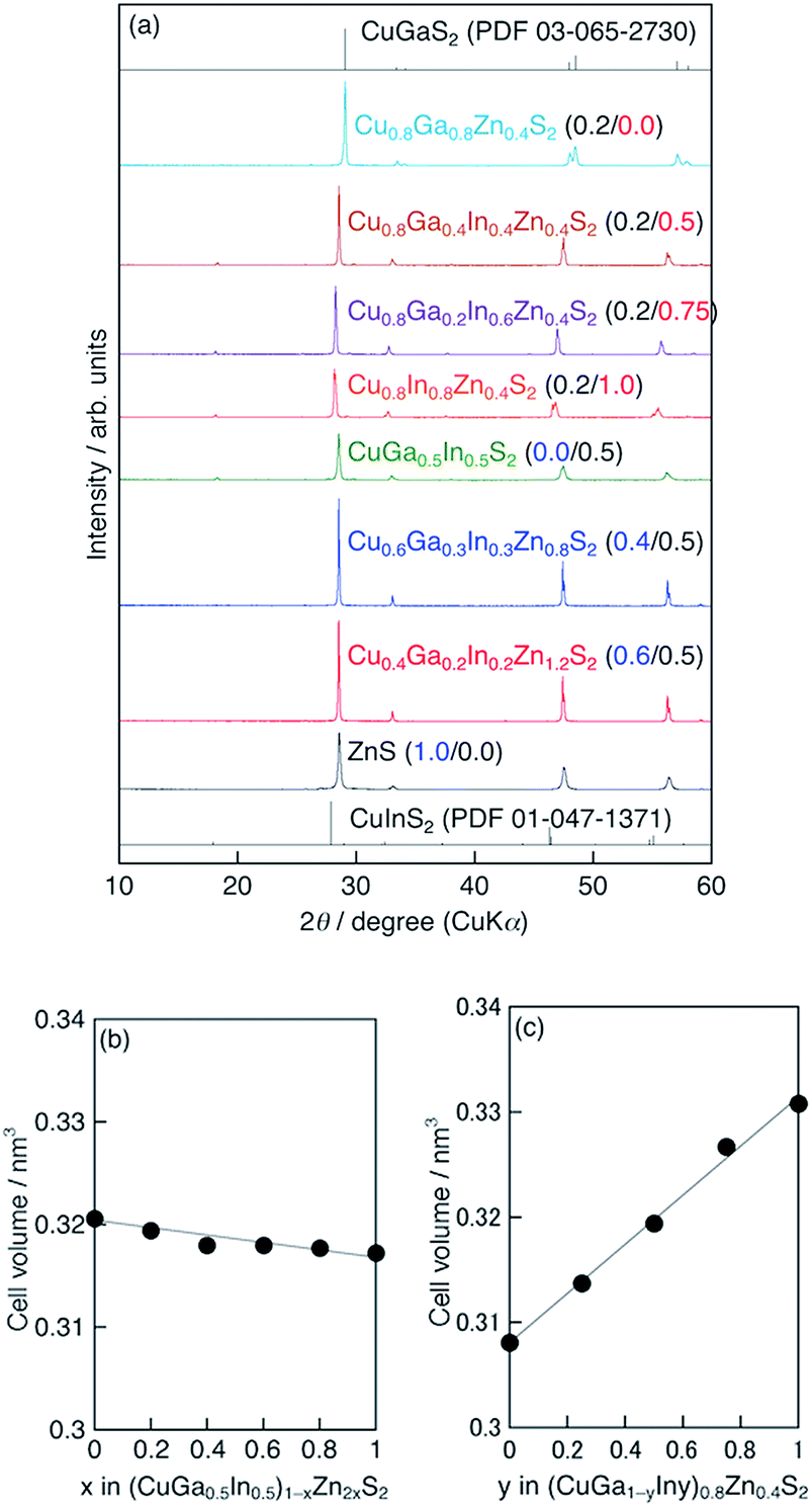 | ||
| Fig. 1 (a) XRD patterns of (CuGa1−yIny)1−xZn2xS2. Cell volumes of (b) (CuGa0.5In0.5)1−xZn2xS2 and (c) (CuGa1−yIny)0.8Zn0.4S2. All samples were prepared by a flux method using a LiCl–KCl (3:2) mixture at 823 K for 15 h (Ga 20% excess). | ||
Fig. 2 shows the SEM and TEM images of the Cu0.8Ga0.4In0.4Zn0.4S2 (x = 0.2, y = 0.5 and Ga 20% excess) powder prepared by the flux method at 823 K for 15 h. The SEM images indicate that highly crystalline powder with a particle size of 1–2 μm was obtained without significant aggregation. Two types of fringe patterns were recognized in TEM images (Fig. 2c). The fringe widths were measured to be 0.31 nm and 0.19 nm, corresponding to the results obtained with the Fourier transformed images (Fig. 2d). Two fringes with the widths of 0.31 nm and 0.19 nm should be assigned to the lattices of the (112) and (220) facets of the chalcopyrite structure based on Bragg's law in XRD results.
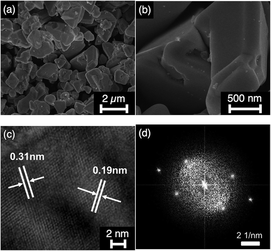 | ||
| Fig. 2 (a and b) SEM image, (c) FE-TEM image of Cu0.8Ga0.4In0.4Zn0.4S2 prepared by a flux method using a LiCl–KCl (3:2) mixture at 823 K for 15 h (Ga 20% excess). (d) Fourier transformed image of FE-TEM fringe patterns of (c). | ||
Fig. 3a and b show the diffuse reflectance spectra (DRS) of (CuGa1−yIny)1−xZn2xS2 (x/y = 0.2/0.0, 0.2/0.5, 0.2/0.75, 0.2/1.0, 0.0/0.5, 0.4/0.5, 0.6/0.5 and Ga 20% excess) solid solutions prepared by a flux method at 823 K for 15 h. The absorption edges of (CuGa1−yIny)0.8Zn0.4S2 solid solutions shifted from 540 nm to 880 nm as the value of y increased (Fig. 3b), so that the band gaps of the solid solutions were estimated to be 1.4 to 2.3 eV. When the value of x increased, the absorption edges of the solid solutions did not change very much in the range of 0 ≤ x ≤ 0.4, while the sample of x = 0.6 possessed a clearly shifted absorption edge at 600 nm (Fig. 3a).
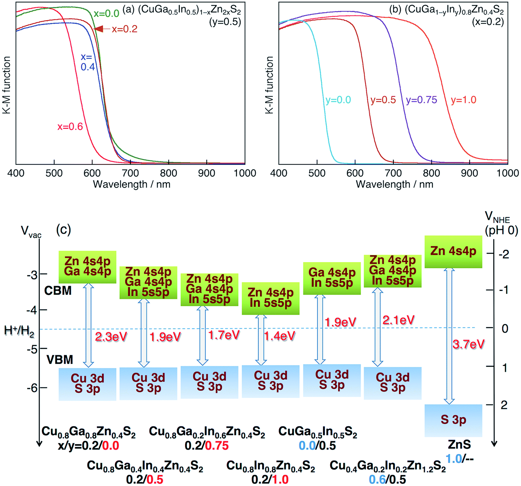 | ||
| Fig. 3 (a and b) Diffuse reflectance spectra of (CuGa1−yIny)1−xZn2xS2 photocatalysts (Ga 20% excess) prepared by a flux method using a LiCl–KCl (3:2) mixture at 823 K for 15 h. (c) Estimated band alignment of CGIZS photocatalysts based on the results of diffuse reflectance spectroscopy and photoelectron spectroscopy measurements (Fig. S6†). Valence band, blue; conduction band, green. | ||
Fig. 3c shows estimated band alignments of typical CGIZS photocatalysts (x/y = 0.2/0.0, 0.2/0.5, 0.2/0.75, 0.2/1.0, 0.0/0.5, 0.6/0.5, 1.0/— and Ga 20% excess), based on the results of DRS and photoelectron spectroscopy in air (PESA) measurements. The results of typical PESA are shown in Fig. S6.† It should be noted that only the conduction band minimum (CBM) shifted positively and the valence band maximum (VBM) kept a constant level with the value of y becoming larger, where the ratio of In to Ga increased. It was also revealed that the CBM shifted negatively gradually and the VBM kept a constant level until x = 0.6 as the value of x became large, where the ratio of Zn to Cu(Ga1−yIny) increased. The change in the band levels was probably due to the VBM consisting of the hybridized orbital of Cu 3d and S 3p and the CBM consisting of the hybridized orbital of Ga 4s 4p, In 5s 5p and Zn 4s 4p.
To compare the flux method with solid-state synthesis, we investigated the effect of the temperatures of synthesis and the composition of the CGIZS photocatalyst on the solid-state synthesis. On the formation of solid-solutions, the XRD patterns of Cu0.8Ga0.4In0.4Zn0.4S2 (x = 0.2, y = 0.5 and Ga 20% excess) prepared at temperatures from 773 K to 1173 K for 10 h indicated that the single phase of chalcopyrite structure was obtained successfully at 923 K or above which was approximately 100 K higher than that of the flux method (Fig. S7†). On the other hand, for CGIZS solid-solutions with chalcopyrite structures formed in all ranges between y = 0.0 and y = 1.0 in (CuGa1−yIny)0.8Zn0.4S2 prepared by solid-state synthesis at 1073 K for 10 h (Fig. S8†), shifting the absorption edges with the change of y values in a similar manner to that of the flux method. Taking the size of crystals into consideration, the crystal-growth in the flux method seems to be much faster than that in solid-state synthesis, because the size of crystals growing in the flux method at 823 K for 15 h was similar to that in solid-state synthesis at 1073 K for 10 h as shown in SEM images (Fig. S5 and S9†).
ICP measurements revealed that excess Ga in the preparation of CGIZS was present in the obtained CGIZS. For example, the net composition of Cu0.8Ga0.4In0.4Zn0.4S2 (Ga 20% excess) with a theoretical ratio of Cu/Ga/In/Zn/S = 0.8:0.48:0.4:0.4:2.12 was estimated to be 0.80:0.50:0.41:0.39:2.12. The excess Ga and/or In exists in the crystal lattice forming Cu(I)-site defects according to charge balance. It was also confirmed by ICP measurements that 200–500 ppm of Li coming from the flux remained in the Cu0.8Ga0.4In0.4Zn0.4S2 solid solution. The small amount of Li could not be removed even after washing CGIZS 7 times with water. This implies that the Li+ ion is substituted in the crystal lattice of CGIZS photocatalysts because the radius of the Li+ ion: 0.59 Å (coordination number 4) is close to those of Cu+: 0.60 Å, Ga3+: 0.47 Å, In3+: 0.62 Å, and Zn2+: 0.60 Å. We would speculate that the lattice-substituted Li might have an effect on the PEC performance of CGIZS as observed in the Cu(In,Ga)Se2 solar cell that shows enhanced performance by the substitution of Na and K.25,26
Photoelectrochemical properties of CGIZS-based photoelectrodes
CGIZS photoelectrodes were fabricated with a particle transfer method which was considered to be an excellent technique for forming photoelectrodes using semiconductor powders.19,20 The SEM images of the Cu0.8Ga0.4In0.4Zn0.4S2 photoelectrode prepared by the particle transfer method are shown in Fig. 4a with a top view and in Fig. 4b with a cross-sectional view. The photoelectrode was constituted of Pt/CdS/CGIZS/Au including a Pt cocatalyst, a CdS modification layer, a CGIZS photocatalyst layer and an Au contact layer. Each layer was identified by EDS elemental mapping analysis, as shown in Fig. 4c–i. The Au layer was 2–5 μm in thickness. CGIZS crystal particles were loaded as a monolayer randomly on the Au layer, and CdS formed a thin layer on CGIZS particles but grew larger in some parts probably as Cd hydroxide.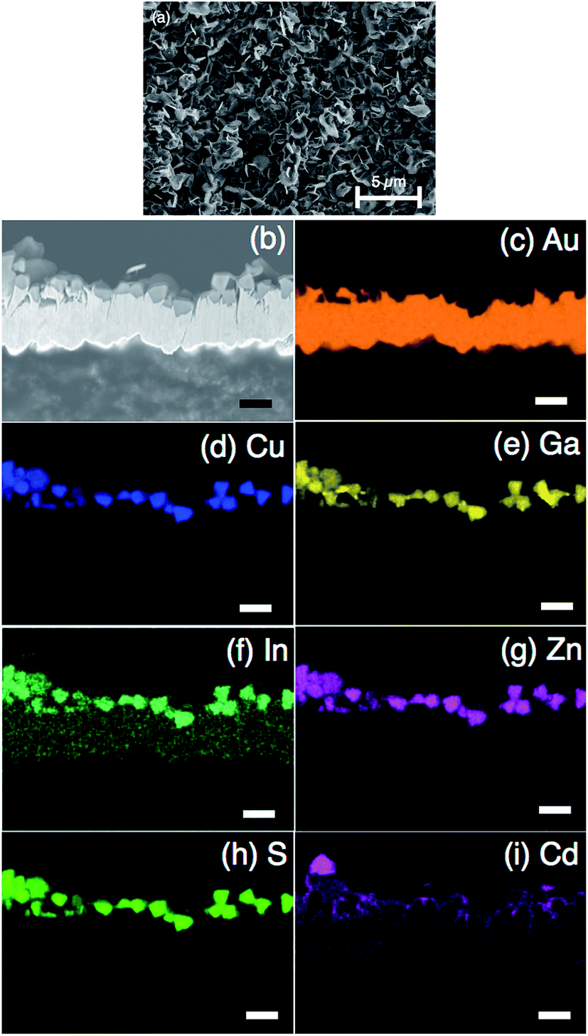 | ||
| Fig. 4 (a) Top view and (b) cross-sectional SEM images of a Pt/CdS/CGIZS photoelectrode. CGIZS represents Cu0.8Ga0.4In0.4Zn0.4S2 (Ga 20% excess) prepared by a flux method using a LiCl–KCl (3:2) mixture at 823 K for 15 h. (c–i) SEM-EDS mapping of the CdS/CGIZS/Au photoelectrode. | ||
The photoelectrochemical measurements of CGIZS-based photoelectrodes were performed under irradiation of simulated sunlight (AM 1.5G) using an electrolyte of phosphate buffer solution (pH 6.4). Fig. 5 shows the I–V curves under chopped simulated sunlight (AM 1.5G) for Cu0.8Ga0.4In0.4Zn0.4S2 (x = 0.2, y = 0.5 and Ga 30% excess)-based photoelectrodes with various surface modifications. It was found that a small cathodic photocurrent was observed with the pristine photoelectrode and the photocurrent density became much larger by modification with CdS and a Pt cocatalyst, which was a well-known surface modification to improve the efficiency of the copper-containing selenide compound-based photocathode.21 Both CdS and Pt modifications led to higher photocurrent densities compared with bare and Pt cocatalyst-loaded electrodes. This PEC property was similar to that of CdS and Pt-modified CIGSe photocathodes.7,12 The cathodic photocurrent was further improved by modification with an amorphous TiO2 layer prepared using a Ti peroxide solution.27,28 The TiO2 layer was expected to act as a layer for electron transfer and a protective layer for CdS against leaching. The saturated photocurrent density of the present material was lower than those of the established CuInS2 (ref. 13 and 29) and Cu2ZnSnS4 (ref. 30) photocathodes. This is because of the difference in the preparation process of the photoelectrodes. The reported CuInS2 and Cu2ZnSnS4 photocathodes are prepared by electrodeposition of constituent metals and subsequent sulfurization to obtain a high-quality film electrode. In contrast, the present photoelectrode is prepared by using photocatalyst particles, and hence the quality of the film is not very high. However, the present photocurrent density is relatively high for a powder-based photoelectrode. The use of photocatalyst powder is essential for the practical use.
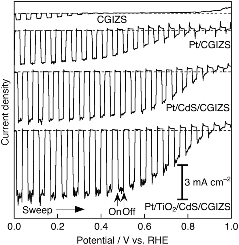 | ||
| Fig. 5
I–V curves of CGIZS photoelectrodes with various surface modifications under simulated sunlight. CGIZS represents Cu0.8Ga0.4In0.4Zn0.4S2 (Ga 20–30% excess) prepared by a flux method using a LiCl–KCl (3:2) mixture at 823 K for 15 h. Electrolyte, aqueous phosphate buffer solution (0.5 mol L−1 of Na2SO4 + 0.25 mol L−1 of NaH2PO4 + 0.25 mol L−1 of Na2HPO4) with pH 6.4; light source, solar simulator (AM 1.5G). | ||
To obtain the maximum performance of the CGIZS photocathode, we examined the effect of the composition of CGIZS on the photocurrent. Cathodic photocurrents were observed for all compositions, and the current densities and onset potentials changed with the compositions. In the present study, the onset potential represents the potential at which the cathodic photoresponse almost disappears. It should be noted that a largely positive onset around 1.0 V vs. RHE was obtained in a wide range of x = 0.2–0.6 and y = 0–0.75. The maximum current density and positive onset potential were obtained for the composition values of x = 0.2 and y = 0.5 in (CuGa1−yIny)1−xZn2xS2, that was Cu0.8Ga0.4In0.4Zn0.4S2 (Table 1). The Ga 4s 4p and Zn 4s 4p form higher conduction band levels than In 5s 5p. Hence, Ga and Zn-containing sulfide possessed a preferred conduction band for water reduction to H2, as shown in Fig. 3c. In contrast, the increase in the ratio of Ga and/or Zn reduces the number of photons absorbed in the CGIZS. As the balance of these factors, Cu0.8Ga0.4In0.4Zn0.4S2 showed the highest photocurrent. On the other hand, the actual onset potential should be determined by the Fermi energy and overpotential for water reduction to H2. The increase in the conduction band levels by contained Ga and Zn will reduce the overpotential to enhance H2 evolution. In contrast, the increase in the ratio of contained Zn decreases the p-type character. In other words, Fermi energy will shift to a negative potential, resulting in the negative shift in the onset potential. Thus, Cu0.8Ga0.4In0.4Zn0.4S2 was the suitable composition to give both excellent cathodic photocurrent and onset potential.
| x | y | Composition formula | Current density/mA cm−2 | Onset potential/V vs. RHE | ||
|---|---|---|---|---|---|---|
| At 0 V vs. RHE | At 0.4 V vs. RHE | At 0.8 V vs. RHE | ||||
|
a CGIZS represents (CuGa1−yIny)1−xZn2xS2 prepared with 20% excess Ga by a flux method using a LiCl–KCl (3:2) mixture at 823 K for 15 h. Electrolyte, an aqueous phosphate buffer solution (0.5 mol L−1 of Na2SO4 + 0.25 mol L−1 of NaH2PO4 + 0.25 mol L−1 of Na2HPO4) with pH 6.4; light source, solar simulator (AM 1.5G).
|
||||||
| 0 | 0.5 | CuGa0.5In0.5S2 | 1.0 | 0.8 | 0 | 0.8 |
| 0.2 | 0 | Cu0.8Ga0.8Zn0.4S2 | 1.1 | 1.0 | 0.3 | 1.0 |
| 0.2 | 0.25 | Cu0.8Ga0.6In0.2Zn0.4S2 | 2.0 | 1.8 | 1.0 | 1.0 |
| 0.2 | 0.5 | Cu0.8Ga0.4In0.4Zn0.4S2 | 4.6 | 4.3 | 1.4 | 1.0 |
| 0.2 | 0.75 | Cu0.8Ga0.2In0.6Zn0.4S2 | 1.7 | 1.6 | 0.1 | 0.9 |
| 0.2 | 1 | Cu0.8In0.8Zn0.4S2 | 0.8 | 0.2 | 0 | 0.5 |
| 0.4 | 0.5 | Cu0.6Ga0.3In0.3Zn0.8S2 | 1.7 | 1.6 | 0.4 | 0.9 |
| 0.6 | 0.5 | Cu0.4Ga0.2In0.2Zn1.2S2 | 0.9 | 0.8 | 0.1 | 0.9 |
| 0.8 | 0.5 | Cu0.2Ga0.1In0.1Zn1.6S2 | 0.8 | 0.2 | 0 | 0.6 |
We also examined the effect of excess amounts of Ga, In and/or Zn in the starting material on the properties of Cu0.8Ga0.4In0.4Zn0.4S2. The effects have been already known as a general treatment to obtain better performance for copper-containing sulfide photocatalysts.15,31 The photocurrent densities in all cases with an excess of Ga, In and/or Zn became larger than that without excess. Moreover, the onset potential in the case of Ga or In excess shifted positively to 1.0 V vs. RHE judging from the I–V curves of CGIZS photocathodes as a function of various excess compositions (Table S1†). The positive shift in the onset potential by the excess Ga and/or In is probably due to the improvement of the p-type character which originated from the increase in the number of Cu vacancies.32
Fig. 6 shows the action spectra of the Pt/TiO2/CdS/CGIZS/Au photocathode at different electrode potentials. The onsets of the action spectra agreed with those of the DRS of the CGIZS powder, indicating that the cathodic photocurrent was generated by band gap excitation of CGIZS with a band structure shown in Fig. 3c. The incident photon-to-current conversion efficiency (IPCE) depended on the electrode potential giving a maximum IPCE of 28% at 0 V vs. RHE under irradiation of 570 nm monochromatic light.
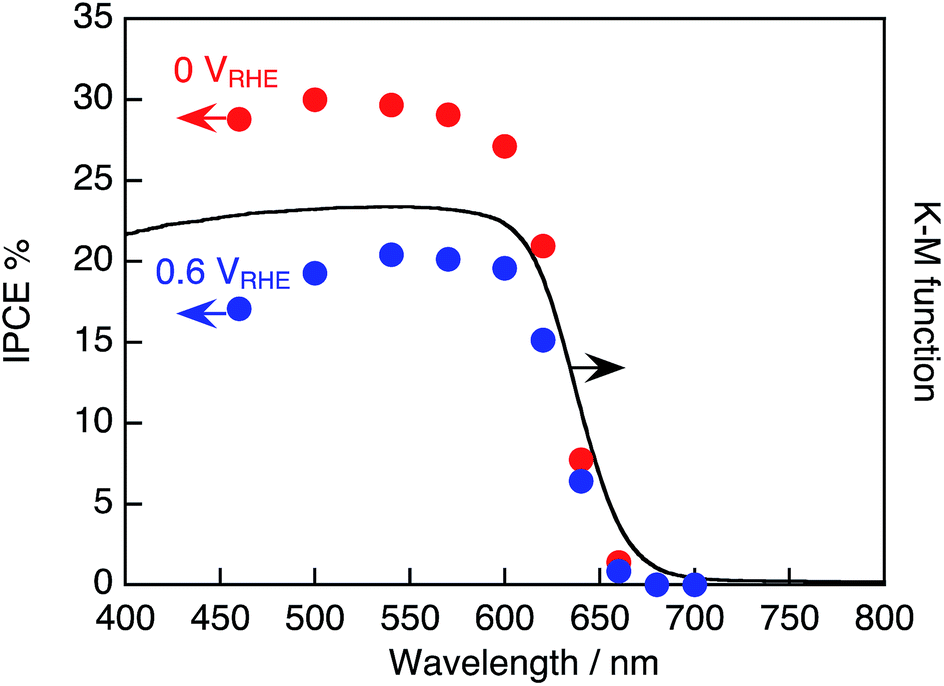 | ||
| Fig. 6 Action spectrum of the Pt/TiO2/CdS/CGIZS photocathode at 0 V and 0.6 V vs. RHE and the diffuse reflectance spectrum of CGIZS powder. CGIZS represents Cu0.8Ga0.4In0.4Zn0.4S2 (Ga 20% excess) prepared by a flux method using a LiCl–KCl (3:2) mixture at 823 K for 15 h. Electrolyte, aqueous phosphate buffer solution (0.5 mol L−1 of Na2SO4 + 0.25 mol L−1 of NaH2PO4 + 0.25 mol L−1 of Na2HPO4) with pH 6.4; light source, 300 W Xe lamp with band pass filters. | ||
The Pt/CdS/CGIZS photocathode using the CGIZS synthesized by a flux method showed much higher photocurrent density than that by solid-state synthesis (Fig. S10†). In spite of no significant difference in XRD patterns and DRS features between two photocatalysts, there was a considerable difference in the photoelectrochemical performance. We guess that the difference would be caused by higher crystallinity with a lower number of defects in the CGIZS photocatalyst prepared by the flux method and/or a small amount of Li impurity from the flux agent.
In the above photoelectrochemical measurements with CGIZS photocathodes fabricated with the particle transfer method, it was clarified that the CGIZS photocathode possessed an appreciably large photocurrent density even if a powdered material was employed. The most remarkable point was a largely positive onset potential reaching closely to 1.0 V vs. RHE, as shown in Fig. 5. The largely positive onset potential obtained for the CGIZS photocathode is more valuable than those of other photocathodes reported so far. The largely positive onset potential of the CGIZS photocathode would be attributed to the VBM around 1.0 V vs. RHE of the CGIZS photocatalysts, which is the advantage of a copper-containing sulfide compound over a similar selenide compound showing 0.7 V vs. RHE.
Photoelectrochemical solar water splitting using the CGIZS photocathode
We have examined PEC water splitting using the Pt/TiO2/CdS/CGIZS photocathode and a CoFeOx/BiVO4 photoanode33 in order to confirm the effectiveness of the powder-based CGIZS photoelectrode fabricated with a particle transfer method. Here, CGIZS represents Cu0.8Ga0.4In0.4Zn0.4S2 (x = 0.2, y = 0.5, Ga 20% excess) prepared by the same flux method as above using LiCl–KCl at 823 K for 15 h. The CoFeOx/BiVO4 photoanode was prepared by synthesizing nanoworm BiVO4 crystals on an ITO substrate and by loading a CoFeOx cocatalyst through cathodic photodeposition.33 Importantly, there was a certain overlapping range between the potentials for the cathodic photocurrent of the Pt/TiO2/CdS/CGIZS and the anodic photocurrent of the CoFeOx/BiVO4 (Fig. S11†). The crossing point on two curves was approximately at 0.6 V vs. RHE showing a corresponding current density of around 1.35 mA cm−2. Considering the irradiated area, the expected photocurrent from the crossing point is 0.67 mA (Fig. S11b†).PEC water splitting was conducted using a two-electrode system in a one-pot flask with no bias under irradiation of simulated sunlight (Fig. S2†). Gas detection was also carried out to confirm if the water splitting proceeds using the two-electrode system, as shown in Fig. 7. A photocurrent of 0.46 mA was observed at the beginning stage, and the value was not very far from the expected photocurrent of 0.67 mA (Fig. S11b†). The photocurrent gradually decreased with irradiation time. In the three-electrode system with an Ag/AgCl reference electrode, the photocurrent of the CoFeOx/BiVO4 photoelectrode was stable, while that of the Pt/TiO2/CdS/CGIZS photoelectrode obviously decreased with irradiation time (Fig. S12†). This indicates that the decreased photocurrent in Fig. 7 is caused by the poor durability of the Pt/TiO2/CdS/CGIZS photocathode. Similarly poor durability was also observed for the Pt/CdS-modified CuInS2 (ref. 29) and Cu2ZnSnS4 (ref. 30) photocathodes due to the photocorrosion of CdS. Although the durability of Pt/CdS/CuInS2 was improved by further modification of a protective TiO2 layer, the TiO2 layer did not work well for the present photoelectrode. Actually, the XPS measurement revealed the reduction of the TiO2 layer after the durability test (Fig. S13†). The faradaic efficiencies were almost 100%. No gas evolution and no current were observed in the dark. These results indicate that the generated photocurrent was used for water splitting into H2 and O2. The initial STH was 1.1% estimated from the observed photocurrent. Even after 1 h irradiation, the STH was 0.7% calculated from the observed photocurrent and evolved gases.
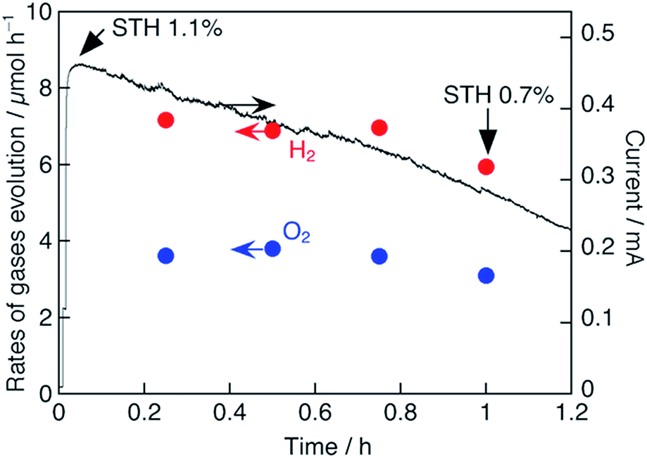 | ||
| Fig. 7 PEC water splitting by using the Pt/TiO2/CdS/CGIZS photocathode (geometric area, 0.231 cm2) and a CoFeOx/BiVO4 photoanode (geometric area, 0.272 cm2) under simulated sunlight irradiation. The CGIZS represents Cu0.8Ga0.4In0.4Zn0.4S2 (Ga 20% excess) prepared by a flux method at 823 K for 15 h. Electrolyte, aqueous phosphate buffer solution (0.5 mol L−1 of Na2SO4 + 0.25 mol L−1 of NaH2PO4 + 0.25 mol L−1 of Na2HPO4) with pH 7.0 adjusted with KOH; light source, solar simulator (AM 1.5G). | ||
Conclusions
The Cu0.8Ga0.4In0.4Zn0.4S2 (x = 0.2, y = 0.5) photocatalyst powder was prepared successfully as a micrometer-sized single phase crystal by a flux method using a LiCl–KCl molten salt (melting point: 625 K at the molar ratio 3:2). The CGIZS-based photocathode (Pt/CdS/CGIZS/Au) fabricated with a particle transfer method exhibited a high IPCE of 28% at 0 V vs. RHE under monochromatic light of 570 nm irradiation and a positive onset potential of 1.0 V vs. RHE. The PEC water splitting with a two-electrode cell combining a modified CGIZS photocathode and a BiVO4 photoanode reached 1.1% STH without an external bias. The high performance obtained in the present study could be attributed to excellent characteristic features of the copper-containing sulfide CGIZS solid solution which can form a chalcopyrite structure with a relatively positive VBM through a wide range of compositions. A high crystallinity prepared by a flux method in a LiCl–KCl molten salt and a particle transfer method as an effective fabrication method also contributed to the high performances of the powder-based photoelectrodes. It is also of great interest in terms of cost reduction that the particulate CGIZS photoelectrode can be fabricated through a facile non-vacuum deposition technique such as spray coating, screen printing, ink-jet printing, squeegee and electrophoretic deposition.
Conflicts of interest
There are no conflicts to declare.Acknowledgements
This work was financially supported by the Japan Technological Research Association of Artificial Photosynthetic Chemical Process (ARPChem) of the New Energy and Industrial Technology Development Organization (NEDO). The authors gratefully thank Mr Y. Hosokawa and Ms K. Kitamura (ARPChem) for their technical support.References
- A. Kudo and Y. Miseki, Chem. Soc. Rev., 2009, 34, 260 Search PubMed.
- T. Hisatomi, J. Kubota and K. Domen, Chem. Soc. Rev., 2014, 43, 7520 RSC.
- M. G. Walter, E. L. Warren, J. R. McKone, S. W. Boettcher, Q. Mi, E. A. Santori and N. S. Lewis, Chem. Rev., 2010, 110, 6446 CrossRef CAS PubMed.
- T. Hamann, Science, 2014, 345, 1566 CrossRef CAS PubMed.
- J. W. Ager, M. R. Shaner, K. A. Walczak, I. D. Sharpae and S. Ardof, Energy Environ. Sci., 2015, 8, 2811 CAS.
- Y. Kuang, Q. Jia, M. Guijun, T. Hisatomi, T. Minegishi, H. Nishiyama, M. Nakabayashi, N. Shibata, T. Yamada, A. Kudo and K. Domen, Nat. Energy, 2016, 2, 16191 CrossRef.
- H. Kumagai, T. Minegishi, N. Sato, T. Yamada, J. Kubota and K. Domen, J. Mater. Chem. A, 2015, 3, 8300 CAS.
- H. Kaneko, T. Minegishi, M. Nakabayashi, N. Shibata, Y. Kuang, T. Yamada and K. Domen, Adv. Funct. Mater., 2016, 26, 4570 CrossRef CAS.
- Y. Goto, T. Minegishi, Y. Kageshima, T. Higashi, H. Kaneko, Y. Kuang, M. Nakabayashi, N. Shibata, H. Ishihara, T. Hayashi, A. Kudo, T. Yamada and K. Domen, J. Mater. Chem. A, 2017, 5, 21242 CAS.
- K. Zhang and L. Guo, Catal. Sci. Technol., 2013, 3, 1672 CAS.
- A. Iwase, Y. H. Ng, R. Amal and A. Kudo, J. Mater. Chem. A, 2015, 3, 8566 CAS.
- W. Septina, Gunawan, S. Ikeda, T. Harada, M. Higashi, R. Abe and M. Matsumura, J. Phys. Chem. C, 2015, 119, 8576 CAS.
- Gunawan, W. Septina, T. Harada, Y. Nose and S. Ikeda, ACS Appl. Mater. Interfaces, 2015, 7, 16086 CAS.
- T. A. Kandiel and K. Takanabe, Appl. Catal., B, 2016, 184, 264 CrossRef CAS.
- I. Tsuji, H. Kato, H. Kobayashi and A. Kudo, J. Phys. Chem. B, 2005, 109, 7323 CrossRef CAS PubMed.
- H. Kaga, K. Saito and A. Kudo, Chem. Commun., 2010, 246, 3779 RSC.
- T. Kato, Y. Hakari, S. Ikeda, Q. Jia, A. Iwase and A. Kudo, J. Phys. Chem. Lett., 2015, 6, 1042 CrossRef CAS PubMed.
- T. Takai, A. Iwase and A. Kudo, 110th CATSJ Meeting, 2012, p. 1J27 Search PubMed.
- M. Kurihara, F. Hayashi, K. Shimizu, H. Wagata, T. Hirano, Y. Nakajima, K. Yubuta, S. Oishi and K. Teshima, Cryst. Growth Des., 2016, 16, 1195 CAS.
- T. Minegishi, N. Nishimura, J. Kubota and K. Domen, Chem. Sci., 2013, 4, 1120 RSC.
- H. Kumagai, T. Minegishi, Y. Moriya, J. Kubota and K. Domen, J. Phys. Chem. C, 2014, 118, 16386 CAS.
- T. W. Kim and K. S. Choi, Science, 2014, 343, 990 CrossRef CAS PubMed.
- M. Zhong, T. Hisatomi, Y. Kuang, J. Zhao, M. Liu, A. Iwase, Q. Jia, H. Nishiyama, T. Minegishi, M. Nakabayashi, N. Shibata, R. Niishiro, C. Katayama, H. Shibano, M. Katayama, A. Kudo, T. Yamada and K. Domen, J. Am. Chem. Soc., 2015, 137, 5053 CrossRef CAS PubMed.
- N. Guijarro, M. S. Prévot, X. Yu, X. A. Jeanbourquin, P. Bornoz, W. Bourée, M. Johnson, F. L. Formal and K. Sivula, Adv. Energy Mater., 2016, 6, 1501949 CrossRef.
- S. Siebentritt, Curr. Opin. Green Sustainable Chem., 2017, 4, 1 CrossRef.
- N. Nicoara, T. Lepetit, L. Arzel, S. Harel, N. Barreau and S. Sadewasser, Sci. Rep., 2017, 7, 41361 CrossRef CAS PubMed.
- C. Pan, T. Takata, M. Nakabayashi, T. Matsumoto, N. Shibata, Y. Ikuhara and K. Domen, Angew. Chem., Int. Ed., 2015, 54, 2955 CrossRef CAS PubMed.
- J. Mulebach, K. Muller and G. Schwarzenbach, Inorg. Chem., 1970, 9, 2381 CrossRef.
- J. Zhao, T. Minegishi, L. Zhang, M. Zhong, Gunawan, M. Nakabayashi, G. Ma, T. Hisatomi, M. Katayama, S. Ikeda, N. Shibata, T. Yamada and K. Domen, Angew. Chem., Int. Ed., 2014, 53, 11808 CrossRef CAS PubMed.
- F. Jiang, Gunawan, T. Harada, Y. Kuang, T. Minegishi, K. Domen and S. Ikeda, J. Am. Chem. Soc., 2015, 137, 13691 CrossRef CAS PubMed.
- H. Kaga, Y. Tsutsui, A. Nagane, A. Iwase and A. Kudo, J. Mater. Chem. A, 2015, 3, 21815 CAS.
- T. Sugiyama, S. Chaisitsak, A. Yamada, M. Konagai, Y. Kudriavtsev, A. Godines, A. Villegas and R. Asomaza, Jpn. J. Appl. Phys., 2000, 39, 4816 CrossRef CAS.
- Y. Kuang, Q. Jia, H. Nishiyama, T. Yamada, A. Kudo and K. Domen, Adv. Energy Mater., 2016, 6, 1501645 CrossRef.
Footnote |
| † Electronic supplementary information (ESI) available: Additional characterization; photoelectrochemical measurements. See DOI: 10.1039/c8se00079d |
| This journal is © The Royal Society of Chemistry 2018 |