Rong
Zhou
,
Jianxing
Huang
,
Shaobo
Lai
,
Jiyang
Li
,
Feng
Wang
,
Zhiqiang
Chen
,
Weiqing
Lin
,
Chao
Li
,
Jing
Wang
* and
Jinbao
Zhao
*
State Key Lab of Physical Chemistry of Solid Surfaces, Collaborative Innovation Center of Chemistry for Energy Materials, College of Chemistry and Chemical Engineering, Xiamen University, Xiamen 361005, P. R. China. E-mail: jbzhao@xmu.edu.cn; wangjing2015@xmu.edu.cn
First published on 23rd April 2018
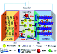
A novel strategy for selecting an additive based on understanding the influence of different functional groups on electrochemical characteristics is adopted. N,N-Diethylamino trimethylsilane (DEATMS) is tested as a bifunctional electrolyte additive to scavenge H2O and neutralize HF in the electrolyte and enhance the behaviour of graphite/LiNi0.5Co0.2Mn0.3O2 cells operating at a high voltage (4.5 V vs. Li/Li+) or elevated temperature (55 °C). With 2% DEATMS, no LiPF6 hydrolysis species is found after storage at 55 °C for 6 days, even with a moisture content of 2000 ppm in the electrolyte. In addition, the graphite/LiNi0.5Co0.2Mn0.3O2 cells containing DEATMS show cycling performances superior to those of the cells without DEATMS upon cycling for 100 cycles at a high voltage (85.5% vs. 72.0%) or high temperature (81.2% vs. 70.6%). The sacrificial oxidation of DEATMS on the cathode surface restricts direct contact between the electrolyte and cathode, improving the electrochemical performance. The ex situ surface analysis of the electrodes after cycling indicates that both the electrolyte decomposition and Mn dissolution are inhibited by the deposition of DEATMS oxidation products.
Several measures for enhancing the performance of cathodes at high voltages have been proposed, e.g., surface coatings of inorganic oxides (Al2O3, SiO2, MgO, and ZrO2etc.)25,26 or organic polymers (PI27 and PEDOT:PSS28etc.), using novel organic solvents with a high anodic stability or adding additives to the electrolyte. A surface coating prevents direct contact between the active material particles and the electrolyte, which restricts the oxidative decomposition of the electrolyte. However, large-scale industrial application of this technique is difficult and involves extra processing costs. Although some novel organic solvents have been reported to be stable over 5 V (vs. Li/Li+), such as nitriles,29,30 sulfones,31 fluorinated carbonates20,32 and ionic liquids,33 these alternative solvents have other problems, such as a lack of SEI formation on the graphite anode, high viscosity, or high cost. The use of electrolyte additives to prevent electrolyte instability at high voltages is cost-efficient and industrially easy to implement.
There are two main types of high-voltage additives that have been widely investigated by scientists. One type is “coordination-type” additives that contain two or more cyano groups (–CN). Succinonitrile (SN) is one of the earliest researched “coordination-type” additives, and Kim et al.34 first reported an improvement in the thermal stability of graphite/LiCoO2 cells because of the complex that formed between the surface metal atoms of LixCoO2 and the cyano groups of SN. Other dinitriles, such as glutaronitrile (GLN),35 adiponitrile (ADN),36 suberonitrile (SUN)37,38 and sebaconitrile (SEN),39 have also been widely investigated as high-voltage additives in academia and the battery industry. The other type of high-voltage additive is “preferentially oxidized-type” additives with highest occupied molecular orbital (HOMO) levels higher than those of the carbonate solvents, and these additives can be preferentially oxidized on the cathode surface. Representatives of this type of high-voltage additive include conductive polymer monomers, such as thiophene,40 and ethylene dioxythiophene (EDOT),41 cyclic compounds, such as 1,3-propanesultone (1,3-PS),42 prop-1-ene-1,3-sultone (PES),43 and methylene methanedisulfonate (MMDS),44,45 and specific phosphites, phosphates and borates,46 such as tris(trimethylsilyl)phosphite (TMSPi),47 tris(trimethylsilyl)phosphate (TMSP),48 and tris(trimethylsilyl)borate (TMSB).49–51 These additives tend to be preferentially oxidized on the cathode surface, and their oxidation products can form a stable film or deposits on the cathode surface over the active sites of the cathode to prevent direct contact between the electrolyte and cathode. By this mechanism, the electrolyte decomposition and side-reactions between the electrolyte and cathode are significantly reduced.
The commercial LIBs electrolyte usually consists of LiPF6 dissolved in a mix of carbonate-based solvents. Nevertheless, LiPF6 has disadvantages such as thermal decomposition at high temperatures and a high reactivity with moisture. These problems are mainly caused by the decomposition of LiPF6, as shown in eqn (1):52–54
LiPF6 ![]() | (1) |
The equilibrium favours the left under normal conditions. Nevertheless, in the presence of H2O, PF5 reacts with H2O and eqn (1) slants towards the right, producing an ionic insulator, i.e., LiF. The reaction of PF5 with H2O, which generates POF3 and HF, and the reaction of POF3 with H2O to produce POF2(OH) and POF(OH)2, are illustrated in eqn (2)–(4):
PF5 + H2O → POF3 + 2HF | (2) |
POF3 + H2O → POF2(OH) + HF | (3) |
POF2(OH) + H2O → POF(OH)2 + HF | (4) |
These solid products LiF, POF2(OH), POF(OH)2 and POF3 will become part of the SEI layer and cause an increase in the cell impedance. Furthermore, the HF that is produced will erode the cathode surface and result in the dissolution of transition metal cations.55 Since water hinders the performance of LIBs, eliminating moisture in batteries is important. One method to eliminate moisture is to use electrolyte additives, which can suppress PF5 hydrolysis by strongly coordinating with PF5, such as hexamethylphosphoramide (HMPA)56 and tris-2,2,2-trifluoroethyl phosphite (TTFP),57 or by strongly coordinating with water molecules, such as lithium 2-trifluoromethyl-4,5-dicyanoimidazole (LiTDI).58
Herein, we focus on a novel bifunctional additive that can scavenge H2O and neutralize HF in the electrolyte and enhance the electrochemical behaviour of a graphite/LiNi0.5Co0.2Mn0.3O2 cell operating at a high voltage (4.5 V vs. Li/Li+) or elevated temperature (55 °C). We first examined the Si–N bond as the main chemical constituent in the additive structure because of its Lewis-base properties and H2O/HF-scavenger ability. Several silazanes containing a Si–N bond have been shown to scavenge H2O and neutralize HF in electrolytes and enhance the cycling and stability of LIBs, for instance, hexamethyldisilazane (HMDS),59 heptamethyldisilazane (HTMDS)60 and 1-(trimethylsilyl)imidazole (1-TMSI).61 We also examined the trimethylsilyl group because it does not have a side effect on the properties of LIBs. In addition, the Si in the trimethylsilyl group reacts with fluorine and reduces LiF on the cathode surface.62,63 Lastly, we examined the diethyl group because of its higher positive inductive effect (+I effect) and ability to increase the HOMO energy of molecules, which ensures preferential oxidation on the cathode surface. Based on the above, we selected N,N-diethylamino trimethylsilane (DEATMS) as an additive, which is functionalized with a Si–N bond, trimethylsilyl group and diethyl group (Fig. 1a). The electrochemical behaviour of DEATMS and its influence on the performance of graphite/LiNi0.5Co0.2Mn0.3O2 cells were investigated by combining theoretical calculations, linear sweep voltammetry (LSV) and cyclic voltammetry (CV), battery measurements with electrochemical impedance spectroscopy (EIS), ex situ Raman spectroscopy, X-ray photoelectron spectroscopy (XPS), transmission electron microscope (TEM), field emission scanning electron microscopy (FE-SEM), and inductively coupled plasma atomic emission spectroscopy (ICP-AES). Few additives have been reported to simultaneously: (1) scavenge H2O and neutralize HF and (2) be preferentially oxidized to improve the electrochemical performance of a cell. Moreover, our strategy for selecting an additive based on understanding the influence of different functional groups on the cell performance may be useful for the design and screening of electrolyte additives.
![]() | ||
Fig. 1 (a) Molecular structure of N,N-diethylamino trimethylsilane (DEATMS). (b) Calculated ΔG in kcal mol−1 for H2O (ΔGHOH) and HF (ΔGHF) with DEATMS. |
The electrochemical charge/discharge behaviours of graphite/LiNi0.5Co0.2Mn0.3O2 cells were tested on a Land CT2001A cell test system based on the protocol below: the current density was C/5 rate for the 1st cycle and followed by 100 cycles at 1C for the constant current/constant voltage (CC/CV) charge and the constant current (CC) discharge mode at room (25 °C) or elevated (55 °C) temperature. The 1C corresponds to 160 mA g−1 for cycling between 3–4.5 V and 145 mA g−1 for cycling between 3–4.3 V. The cut-off current of the constant voltage was 10% of the charging current. The EIS tests were performed under charged state, with the frequency ranging from 100 kHz to 0.1 Hz and the amplitude of 10 mV, by using a PGSTAT 302N electrochemical station (Autolab Metrohm, Switzerland). The self-discharge tests were carried out based on the following procedure: the current density was C/5 rate for the 1st cycle and followed by 10 cycles at 1C for the CC/CV charge and the CC discharge mode at room temperature (25 °C). Afterwards, the cells were charged to 4.3 V for the CC/CV charge mode, and reserved at OCV for 7 days at 55 °C.
To evaluate the impact of using DEATMS as a water scavenger, the moisture content of the electrolyte, in the presence or absence of DEATMS, was enriched by 2000 ppm to speed up the electrolyte hydrolysis, and the added molar ratio of DEATMS:
H2O was slightly above 1
:
1. As Fig. 2a shows, both the fresh baseline electrolyte and 2% DEATMS electrolyte are colourless. After the water enrichment and storage at 55 °C for one day, the baseline electrolyte was brown (Fig. 2b). As the storage time continued, the colour change became more obvious (Fig. 2c), and the baseline electrolyte was dark brown on the sixth day (Fig. 2d). However, the 2% DEATMS electrolyte remained colourless after 6 days of storage at a high temperature. This agreed with the result provided by Wilken et al.,65 and their work showed that the colour change was indicative of LiPF6 electrolyte degradation.
The fresh baseline electrolyte, 2% DEATMS electrolyte and their H2O-enriched equivalents were characterized by 31P NMR after 6 days in storage at 55 °C. As seen in Fig. 2e and f, the 31P spectra of the fresh baseline and 2% DEATMS electrolyte contain a septuplet signal centred at −144.3 ppm, which belongs to the PF6− anion. After storage at 55 °C for 6 days, a new triplet signal centred at −15.9 ppm (1JP-F = 946 Hz, attributed to OPF2OR-type compounds) and two new doublet peaks centred at −7.3 ppm (1JP-F = 937 Hz, attributed to OPF(OR)2-type compounds) and −7.5 ppm (1JP-F = 921 Hz, attributed to OPF(OR)2-type compounds) emerged (Fig. S2, ESI†). To our knowledge, OPF2OR and OPF(OR)2-type compounds are common degradation products of LiPF6-based electrolytes.53,54,65 Conversely, after 2% DEATMS was added to the baseline electrolyte, no LiPF6 hydrolysis species were observed after storage at 55 °C for 6 days with the water enrichment, and only the PF6− septuplet signal was presented in the 31P spectrum, which indicated that LiPF6 hydrolysis did not occur in the 2% DEATMS electrolyte. These NMR results were consistent with the lack of a significant colour change in the 2% DEATMS electrolyte.
To further investigate the effect of using DEATMS as an HF scavenger, a storage experiment with LiNi0.5Co0.2Mn0.3O2 powders and the HF-enriched electrolyte was conducted with and without DEATMS. The storage experiment illustrations are presented in Fig. 2g. All the components were assembled and sealed in an argon glovebox before storage, and the added molar ratio of DEATMS:
(H2O + HF) was slightly higher than 1
:
1. HF is known to be a major cause of the dissolution of transition metal cations on cathodes.55 After storage at 55 °C for 3 days, a metal ion test (ICP-AES) was performed on the electrolyte supernatant after centrifugation (Fig. 2h). The concentration of Mn ions dissolved in the 2% DEATMS electrolyte (8.5 ppm) was much lower than that in the baseline electrolyte (200 ppm), which verified that DEATMS can effectively scavenge HF in the electrolyte.
The theoretical calculations and storage experiments after adding water or HF to the electrolyte proved that the electrolyte stability is adequately enhanced by the H2O/HF-scavenger properties of DEATMS. DEATMS is crucial to achieve a high stability electrolyte, particularly in the presence of high moisture levels or HF.
Molecule | HOMO (eV) | LUMO (eV) |
---|---|---|
EC | −8.73 | 0.02 |
DMC | −8.47 | 0.06 |
DEATMS | −5.70 | −0.05 |
To investigate the anodic stability of DEATMS, LSV experiments were conducted with a three-electrode cell using Pt as the working electrode. As shown in Fig. S3 (ESI†), the baseline electrolyte did not decompose until 5.0 V (vs. Li/Li+), but the starting oxidation potential of the DEATMS-containing electrolyte is approximately 3.5 V (vs. Li/Li+). It is noteworthy that the oxidation potential of baseline electrolyte acquired from LSV is evidently higher than that from the common sense, i.e., 4.4 V vs. Li/Li+. That is because unlike a real cathode, which is an interactive transition metal rich surface and possesses highly catalytic nature, an inert Pt working electrode usually gives higher value of oxidation potential.20,66 As expected, DEATMS possesses a lower oxidation potential than the carbonate solvents, and thus, DEATMS will be preferentially oxidized on the cathode surface. The DEATMS oxidation products can deposit on the cathode surface and cover the cathode active sites, which can effectively prevent continuous electrolyte decomposition at a high voltage.
To further investigate the cathodic stability of DEATMS, CV experiments were conducted with a three-electrode cell using graphite as the working electrode. As shown in Fig. S4 (ESI†), the cathodic stability of the DEATMS-containing electrolyte is nearly the same as that of the baseline electrolyte, and no significant differences were observed in the graphite electrode during the first three CV cycles for the cells with and without DEATMS. A reduction peak was observed at approximately 0.7 V before the Li intercalation reaction in the baseline and DEATMS-containing electrolyte and was ascribed to the reduction of EC to form the SEI layer on the graphite surface. The DFT calculations and CV results show that DEATMS will not participate in the reductive reaction on the anode surface and does not negatively affect the performance of the anode material.
To verify the different influences of DEATMS on the cathode and anode, the electrochemical properties of a Li/LiNi0.5Co0.2Mn0.3O2 cell and Li/graphite cell with DEATMS as an electrolyte additive were tested. As shown in Fig. S5a (ESI†), the Li/LiNi0.5Co0.2Mn0.3O2 cell with DEATMS showed a better cycling performance than the cell with the baseline electrolyte owing to the preferential oxidation of DEATMS. In contrast, the Li/graphite cells with different electrolytes showed nearly the same cycling stability, as presented in Fig. S5b (ESI†), which confirmed that DEATMS does not deteriorate the performance of the graphite anode.
To confirm whether DEATMS deposited on the cathode surface, the TEM images of pre-cycled LiNi0.5Co0.2Mn0.3O2 cathodes are depicted in Fig. 4a–d. After pre-cycling with the baseline electrolyte, a non-uniform surface layer with thickness from 0–60 nm is observed on the surface of cathode particles, which is derived from electrolyte decomposition at high voltage (Fig. 4c and d). This uneven surface layer cannot prevent the electrolyte from continuously decomposing as cycling progressed. While in DEATMS-containing electrolyte, the passivation layer is formed uniformly on the cathode surface with much thinner thickness than that formed in baseline electrolyte, approximately 5 nm (Fig. 4a and b). The constituents of the passivation layer on the pre-cycled LiNi0.5Co0.2Mn0.3O2 cathode were further investigated by using XPS. As seen in Fig. S6 (ESI†), the N 1s peak intensity in the XPS spectra of the cathode with DEATMS is obviously higher than that with the baseline electrolyte. However, the Si 2p peaks in the XPS patterns of the cathode with DEATMS or the baseline electrolyte were not substantially different. Because of the high valence of the Si atom and easy breakage of the Si–N bond, the Si–N bond may break during the oxidative decomposition of DEATMS. The –N group will deposit on the cathode surface due to the strong complex formation between the surface metal atoms and the lone electron pair of the N atom. Conversely, the saturated –Si will dissolve into the electrolyte. This conjecture is consistent with the above XPS results.
The electrochemical performances of graphite/LiNi0.5Co0.2Mn0.3O2 cells under different conditions are shown in Fig. 3. When they were cycled between 3.0–4.3 V at 25 °C, the cells showed similar discharge capacity retentions and coulombic efficiencies after 100 cycles (Fig. 3a and S7a (ESI†)), which confirmed that DEATMS does not remarkably influence the behaviour of cells operating between 3.0–4.3 V at 25 °C. When the charging cut-off voltage was increased to 4.5 V (Fig. 3b and S7b (ESI†)), the cell with DEATMS had a high specific capacity of 148.1 mA h g−1 after 100 cycles and a high average coulombic efficiency with a capacity retention of 85.5% at a 1C charging/discharging rate. In comparison, the baseline cell showed a specific capacity of 125.0 mA h g−1 and a capacity retention of 72.0%. Moreover, the voltage profiles of the baseline cell dramatically changed during long-term cycling (Fig. 3c). The charging slope increasingly shifted to high values; however, the voltage slope of discharging shifted to low values during cycling. In contrast, both the average charge and discharge voltages of the DEATMS cell were extremely stable as cycling progressed, and the capacity retention was better (Fig. 3d).
This improvement can also be interpreted by the lower impedances of the DEATMS-containing cell after cycling. The impedances, which consist of the bulk resistance (Rs), passivation layer resistance on the cathode (RSEI,CA), SEI resistance on the anode (RSEI,AN) and charge transfer resistance (Rct),67 were analysed with an equivalent circuit diagram, as presented in Fig. 3e, and the fitting parameters are outlined in Table 2. A dramatic difference was not observed in the Rs. The RSEI,CA of the DEATMS-containing cell was slightly higher than that of the baseline cell due to the deposition of DEATMS oxidation products on the cathode surface. However, the RSEI,AN (14.1 Ω) and Rct (28.6 Ω) of the baseline cell were substantially larger than those of the DEATMS cell (5.1 and 20.7 Ω, respectively), which suggested that DEATMS may efficiently suppress the electrolyte decomposition on the anode surface and enhance the charge transfer between the electrodes and the electrolyte. Therefore, the overall cell resistance (the sum of Rs, RSEI,AN, RSEI,CA, and Rct) of the baseline cell was much higher than that of the DEATMS-containing cell.
Fitted resistances (ohm) | R s | R SEI,AN | R SEI,CA | R ct | R sum | |
---|---|---|---|---|---|---|
After 4.5 V | Baseline | 2.1 | 14.1 | 3.0 | 28.6 | 47.8 |
cut-off cycling | DEATMS | 2.3 | 5.1 | 9.5 | 20.7 | 37.6 |
The normalized Raman spectra of the cathodes in the pristine state and after cycling between 3.0–4.5 V are presented in Fig. S8 (ESI†). The pristine LiNi0.5Co0.2Mn0.3O2 electrode displays the A1g and Eg bands for the v (MO6) vibrations (at approximately 600 cm−1) and δ (O–M–O) vibrations (at approximately 500 cm−1), respectively.68 During the charging step, a new band appeared at approximately 545 cm−1 and showed a constant increase in intensity upon delithiation.69 Singh et al. assigned this new band to the A1g band of Ni3+, which is present due to the oxidation of Ni2+,70 because the Raman spectra of LiNiO2, in which Ni is present in the +3 oxidation state, show an A1g band at 545 cm−1.71 Normally, this new band will completely disappear due to the reduction of Ni3+ during the discharge step. However, continuous structural degradation occurs on the surface of LiNi0.5Co0.2Mn0.3O2 during high-voltage cycling. The electrode polarization becomes more severe, preventing full lithiation of the cathode, even at 3.0 V, and causing a Li deficiency on the cathode surface.72 Thus, some Ni3+ must remain on the cathode surface at 3.0 V to achieve charge neutrality. As the LiNi0.5Co0.2Mn0.3O2 surface degradation increases, the intensity of the A1g band of Ni3+ also increases, as shown in the Raman spectra. Clearly, the ratio of A1g-Ni3+/A1g on the cathode surface with the DEATMS electrolyte was significantly lower than that with the baseline electrolyte, which indicated that structural degradation of the LiNi0.5Co0.2Mn0.3O2 surface was suppressed in the presence of DEATMS.
The SEM images of the cathodes cycled with the DEATMS-containing electrolyte or the baseline electrolyte are shown in Fig. 4e–g. As presented in Fig. 4e, the spherical particles of LiNi0.5Co0.2Mn0.3O2 are obvious on the fresh cathode, and the rope-like material is conductive carbon black. After cycling with the baseline electrolyte at a high voltage for 100 cycles, some of the LiNi0.5Co0.2Mn0.3O2 particles sustained severe degradation, and some cracks appeared on the surfaces of the particles (Fig. 4f). This phenomenon can be attributed to the dissolution of the transition metal from the cathode surface upon operating between 3.0–4.5 V.73 Nevertheless, in the presence of the DEATMS-containing electrolyte, the structure of the LiNi0.5Co0.2Mn0.3O2 particles was well maintained (Fig. 4g). This indicated that the DEATMS oxidation products deposited on the cathode surface can preserve the cathode upon cycling at a high voltage.
To further understand the surface composition of the cathode operated at a high voltage, XPS was used to determine the constituents on the cathode surface. Fig. 4h–j shows the XPS F 1s, P 2p and N 1s spectra of the LiNi0.5Co0.2Mn0.3O2 electrode surface after 100 cycles with the 0.5% DEATMS electrolyte or baseline electrolyte. The main peak in the F 1s spectra at 685.0 eV belongs to LiF, and the peak at 687.2 eV corresponds to the decomposition products of LiPF6 (LixPFy and LixPFyOz, denoted P–F) overlapping with the signal of fluorine in PVdF.61 The LiF peak intensity was stronger for the cathode with the baseline electrolyte than that with the DEATMS-containing electrolyte. LiF is attributed to the decomposition of LiPF6 and could result in increased cell impedance. In the P 2p spectra, the peaks at 136.3 eV and 134.4 eV can be assigned to LixPFy and LixPFyOz, which are due to LiPF6 decomposition on the cathode surface.73 The intensities of LiF, LixPFy and LixPFyOz were weaker on the cathode surface containing 0.5% DEATMS than those for the cathode cycled with the baseline electrolyte, which showed that the decomposition of LiPF6 on the cathode surface was suppressed in the DEATMS-containing electrolyte. The N 1s peak intensity in the XPS spectra of the cathode with DEATMS was higher than that for the cathode with the baseline electrolyte, which indicated that the DEATMS oxidation products deposited on the cathode surface are stable and will not break away from the cathode surface, even after 100 cycles at a high voltage.
The SEM images of the graphite anodes in the pristine state and after operating between 3.0–4.5 V are shown in Fig. S9 (ESI†). The graphite particles were obvious before cycling, as shown in Fig. S9a.† However, after 100 cycles at a high voltage with the baseline electrolyte, the particles were encased by a thick SEI film and had round edges and rough surfaces (Fig. S9b†). This is due to the transition metal ions deposition from the cathode, resulting in continuous electrolyte decomposition. In contrast, the particles were still recognizable after cycling with the DEATMS-containing electrolyte and maintained sharp edges and smooth surfaces (Fig. S9c†). These behaviours agree with the EIS data shown in Fig. 3e.
XPS was used to further comprehend the surface composition of the cycled graphite anodes. As seen in Fig. S10 (ESI†), the F 1s spectra of the anodes showed two main peaks. The peak at 685.0 eV corresponds to LiF, and the peak at 687.2 eV corresponds to other LiPF6 decomposition products (denoted P–F).61 In the P 2p spectra, the peak at 136.5 eV represents LixPFy, while the peak at 133.2 eV can be assigned to LixPFyOz.43 The graphite anode with the DEATMS-containing electrolyte displayed weaker intensities for LixPFy, LixPFyOz and LiF, and these results and the SEM images of the graphite anodes indicate that electrolyte decomposition on the graphite surface is also inhibited in the presence of DEATMS.
Transition metal (especially Mn) ion dissolution from LiNi0.5Co0.2Mn0.3O2, which is usually triggered by HF, is a vital element that is responsible for capacity fading at high temperatures. The amount of dissolved Mn in the electrolyte and the deposition on the graphite anode after 100 cycles at 55 °C were tested by ICP-AES, as shown in Fig. 5b. Fewer Mn ions were detected in the cell cycled with the DEATMS-containing electrolyte than the baseline cell. In other words, the deposited DEATMS oxidation products protected the LiNi0.5Co0.2Mn0.3O2 surface from HF attack, resulting in less Mn dissolution.
The electrolyte decomposition extent can be evaluated via testing the self-discharge of cells at a state of charge (SOC) of 100%. Hence, self-discharge tests were performed for the graphite/LiNi0.5Co0.2Mn0.3O2 cells with and without DEATMS at an elevated temperature. The change in the cell OCV as a function of the storage time is depicted in Fig. 5c. In contrast to the additive-containing cell, a rapid OCV drop was observed in the cell without DEATMS, which indicated rapid re-lithiation via self-discharge. Thus, the self-discharge rate of the cell with DEATMS at a 100% SOC is smaller than that of the cell without DEATMS due to suppressed electrolyte oxidation.
Footnote |
† Electronic supplementary information (ESI) available. See DOI: 10.1039/c8se00064f |
This journal is © The Royal Society of Chemistry 2018 |