
A techno-economic analysis method for guiding research and investment directions for c-Si photovoltaics and its application to Al-BSF, PERC, LDSE and advanced hydrogenation†
Nathan L.
Chang
a,
Anita
Ho-Baillie
 *a,
Stuart
Wenham
a,
Michael
Woodhouse
b,
Rhett
Evans
a,
Budi
Tjahjono
c,
Fred
Qi
a,
Chee Mun
Chong
a and
Renate J.
Egan
a
*a,
Stuart
Wenham
a,
Michael
Woodhouse
b,
Rhett
Evans
a,
Budi
Tjahjono
c,
Fred
Qi
a,
Chee Mun
Chong
a and
Renate J.
Egan
a
aSchool of Photovoltaic and Renewable Energy Engineering, University of New South Wales, Sydney 2052, Australia. E-mail: a.ho-baillie@unsw.edu.au
bNational Renewable Energy Laboratory, Golden, CO, USA
cSunrise Global Solar Energy Co, Yilan, Taiwan, ROC
First published on 28th February 2018
Abstract
A techno-economic analysis method is used to analyse industry standard mono crystalline silicon photovoltaic technologies – Aluminium Back Surface Field (Al-BSF) and Passivated Emitter and Rear Cell (PERC), together with promising process variations – Laser Doped Selective Emitter (LDSE) and three implementations of advanced hydrogenation. Building on a previously reported manufacturing cost and uncertainty analysis method, the impact of uncertainty in module performance and market price is added to estimate the manufacturer's gross margin. Two additional interpretation methods are described – (i) simultaneous Monte Carlo and (ii) contribution to variation – that help distinguish the impact of small differences between sequences, and identify the most important factors (cost, performance or market) affecting commercial viability. Combining these methods allows a rapid commercial viability assessment without requiring exact data on all the inputs. The analysis indicates that PERC is more commercially attractive than Al-BSF, with a median improvement in manufacturer's margin >5%. Al-BSF + LDSE is found to reduce manufacturer's margin. The PERC + LDSE and PERC + advanced hydrogenation sequences are estimated to provide a median margin improvement >2% compared to PERC alone. The advantage of PERC + LDSE depends strongly on delivering the expected 0.9%abs cell efficiency gain with high production yields and receiving a selling price premium for higher power modules; less important is the production cost of the LDSE process steps. The advantage of advanced hydrogenation depends strongly on achieving the expected 0.2%abs as-produced efficiency gain with high production yield, as well as realising a 0.5% selling price premium for being “CID-Free”; these factors outweigh the production costs of the alternative hydrogenation processes.
1 Introduction
Significant resources are devoted to developing new photovoltaic technologies, both within institutes and research and development (R&D) teams within commercial companies. Typically, technologies proceed through various stages of development. These stages can be categorised in different ways, such as various Technology Readiness Level (TRL) scales.1,2 As a technology proceeds through each stage, progressively larger investments are required to scale up the cell and module size and production volumes, which presents increasing risk to the investor. Thus investors require convincing evidence of its commercial potential in order to support a technology into each new stage of commercialisation.Such evidence may include projections of manufacturing cost, cell and module performance and market studies. In many cases these three factors must be considered concurrently to adequately assess a technology. However each of these factors has significant uncertainty. As discussed in previous work,3 it can be difficult to obtain precise data for cost inputs required to calculate the manufacturing cost, and a method was presented that delivers effective cost analysis by taking into account these uncertainties. In this work, we extend this methodology from low TRL technologies, with significant uncertainties in materials and processes to pre-commercial silicon wafer based technologies. In doing so, we advance the method to include the effect and uncertainty of cell and module performance and market factors into a concurrent techno-economic assessment of five c-Si PV technologies. The technologies considered are;
(i) Aluminium Back-Surface-Field (AlBSF), shown schematically in Fig. 1a, has for many years now been the standard cell fabrication process for mono-crystalline and multi-crystalline solar cells.4 This technology forms a lightly Al doped rear layer (the “Back Surface Field”) on the rear of the cell, and includes silver screen printed Ag front grid.
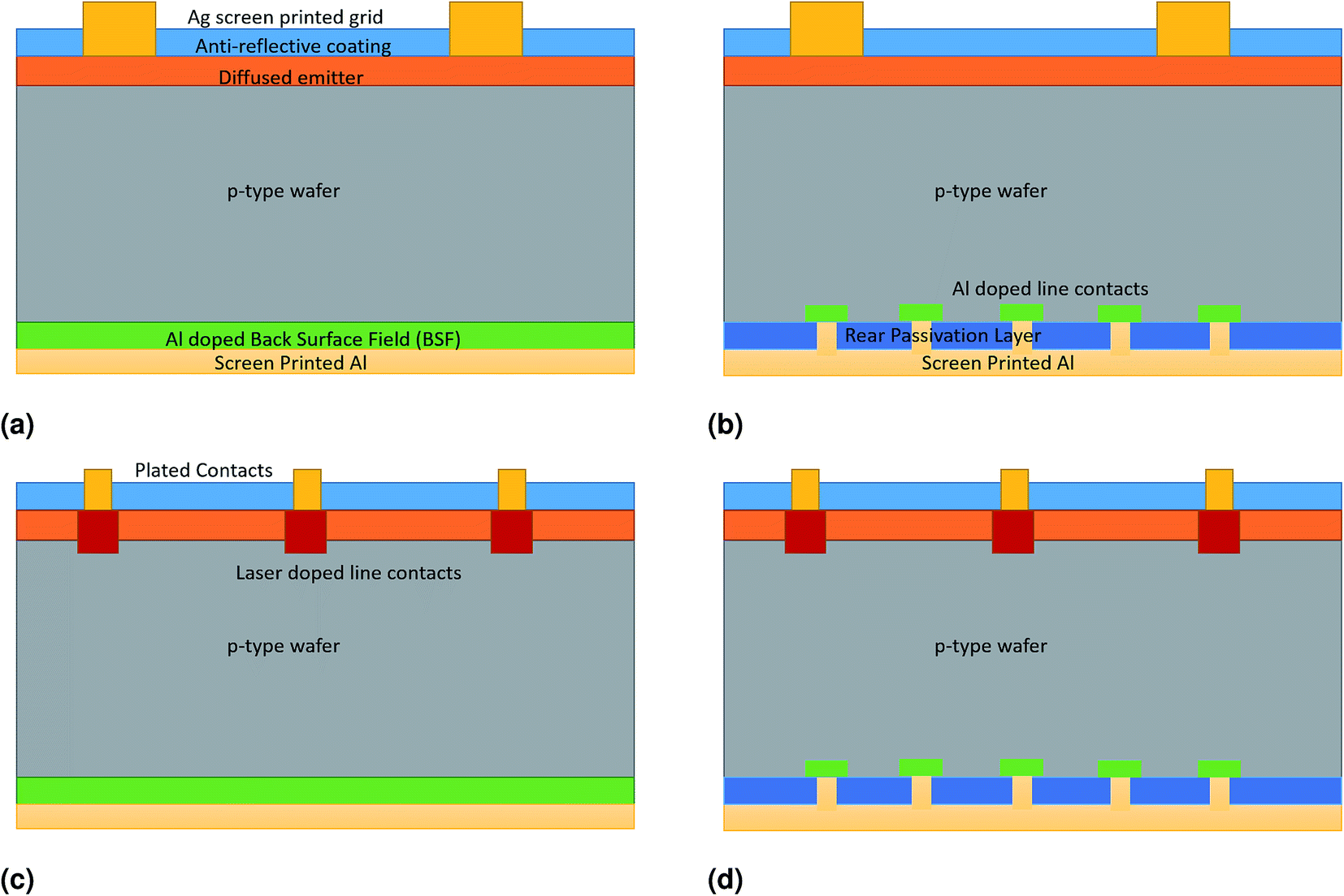 | ||
| Fig. 1 Structure of (a) Al-BSF, (b) PERC, (c) LDSE and (d) PERC + LDSE c-Si cells. The diagrams are not to scale, and sunlight arrives from the direction of the top of the page. | ||
(ii) Passivated Emitter and Rear Cell (PERC), originally developed at UNSW, as shown in Fig. 1b. PERC is becoming the new manufacturing standard, expected to increase its market share from the current 20% in 2017 to over 40% by 2021.4,5 The PERC technology includes a passivation layer on the rear of the cell that reduces recombination and improves voltage and efficiency. The efficiency benefit compared to Al-BSF is currently 1.3%abs, expected to increase to 2%abs by 2027.4
(iii) Laser Doped Selective Emitter (LDSE) technology, also developed at UNSW and commercialised by Suntech as the Pluto technology.6 This structure (Fig. 1c) has the same rear as the Al-BSF technology, but improves the front of the cell through selective emitter formation with a laser and plating of these contacts. This delivers an efficiency boost through reduced front surface contact coverage (shading) and lighter emitter doping across the light exposed area of the cell. As a result, the reported efficiency benefit of LDSE compared to Al-BSF was 1.8%abs at the cell level. As an illustration of how technologies develop in a competitive manufacturing environment, improvements in the silver pastes used in the screen printing process of the standard Al-BSF technology allowed lower doped emitters to be used for the Al-BSF technology, improving its relative performance to the LDSE implementation, and thus reducing the competitive advantage of LDSE. Suntech stopped its use of the LDSE technology after around 4 years of commercial production.
(iv) Combined PERC and LDSE sequence, as shown in Fig. 1d. This combination, which has been developed and demonstrated at UNSW,7,8 delivers the reduced rear surface recombination benefits of PERC with the improved front surface recombination and reduced shading of LDSE to deliver higher efficiencies than PERC or LDSE alone. We need to consider this performance benefit together with differences in manufacturing cost and market impact in order to fully evaluate the commercial potential of this technology and to assess whether it has potential as the next step after PERC, and;
(v) Advanced hydrogenation, being piloted in manufacturing as described by Hallam et al.,9 improves the wafer material quality by the application of light in conjunction with heat at the end of the cell fabrication process. Hallam et al. describe a test on mono-crystalline PERC cells using a high intensity laser of >100 suns illumination (“Laser Hydrogenation”) after the screen print firing step. The as-produced efficiency of the cells increased, and there was a reduction in “Carrier Induced Degradation” (CID), enabling the cells to be described as “CID-Free”. Note that the CID effect has been variously termed “Light and Elevated Temperature-Induced Degradation” (LeTID) and “Light Induced Degradation” (LID) as the understanding of this effect has changed over time. Hallam et al. discuss alternative manufacturing implementations of this process, including the integration of high intensity lights into the screen print firing furnace (“Furnace Hydrogenation”) or into the laminator of module fabrication (“Laminator Hydrogenation”). In more recent work, Hallam et al.10 describe tests using laser hydrogenation as well as LED illumination (“LED Hydrogenation”) and halogen illumination (“Halogen Hydrogenation”), with similar performance gains from each method. In this work we analyse three possible implementations of advanced hydrogenation – laser, LED and furnace hydrogenation. Regardless of the process implementation used, there is a requirement for either an additional process step or a modification of the screen printing firing step, which leads to a higher manufacturing cost per cell. The impact of CID on module performance varies over time, with a reduction in module performance, followed by a slow recovery.11,12 The presence of CID in a module would be expected to impact the selling price. We must therefore evaluate the manufacturing cost, performance and market value of the modules simultaneously in order to assess the commercial potential and identify the critical factors to commercialisation of this technology.
The cost and benefit of both commercialised and near-commercial photovoltaic technologies has been reported in different ways in the literature and the public domain. For the commercialised technologies, publicly traded PV manufacturing companies report the average manufacturing cost, for example an earnings report from Jinko Solar.13 However these reports record average costs over the entire production capacity, do not reveal the breakdown of individual process steps, and the assumptions such as depreciation schedules are not clear. There are also reports and data of the average selling price or spot prices of modules, for example EnergyTrend.14 These do not accurately reflect the cost of manufacture, since they are strongly influenced by market forces, such as under or over supply. For commercial-ready technologies, cost studies provide a greater level of detail, and outline the assumptions, such as Goodrich et al.15,16 and Powell et al.17–19 Woodhouse et al.20 has a study in preparation assessing the PERC sequence. For the LDSE technology, there exists a UNSW study in 2011,21 considering the performance and cost benefits.
In this work, we record advances in the uncertainty-led cost benefit analysis methodology previously reported,3,22 and apply it to the Al-BSF, PERC, LDSE and advanced hydrogenation technologies to assess the relative commercial potential of each, identifying key impact factors that inform manufacturing implementation. This is to our knowledge the first time that LDSE combined with PERC, and advanced hydrogenation have been assessed in a detailed manufacturing cost-benefit analysis.
2 Methods
In this work, we report an extension of the uncertainty analysis method used previously.3,22 In the earlier work, techno-economic analysis of low TRL monolithic thin film perovskite technologies was conducted, where the uncertainties in the cost of the emerging technologies were assessed using a Monte Carlo analysis to calculate the cost of manufacture in $ m−2. A brief summary of the method is provided below (Section 2.2). We extend the method to apply it to more commercial-ready silicon-based technologies (Section 2.1), where in addition to assessing the uncertainty in production costs, we include the uncertainty in module performance (taking into account manufacturing yield, cell efficiencies, cell to module impacts and module efficiency, as discussed in Sections 2.2 and 2.3) and uncertainty in the impact of process changes on the market value of the modules (such as higher prices for higher power or higher energy yield modules as discussed in Section 2.4).In analysing these results, we extend the method through the use of simultaneous Monte Carlo analysis (Section 2.5) to more easily see small differences between process sequences, as well as a contribution to variance analysis (Section 2.6) to identify the key factors impacting a decision of whether to proceed with investment into a new technology.
2.1 Process definition and global factory assumptions
For this work we considered a number of commercial and near commercial ready silicon wafer based cell fabrication sequences for analysis. In Table S1† we list the sequences, and comment on their stage of demonstration or commercialisation and some references for each. For each of the sequences we are considering, there can be variations in the selection and order of the processes. It is beyond the scope of this work to analyse in detail all the permutations of each sequence, so we have defined a representative list of processes for each in Table S2† based on discussions with industry and researchers.23,24Other factory assumptions are given in Table S3.† For this work, we have assumed a throughput to match the data from Woodhouse et al., which has a throughput assumption of 500 MW per year.
2.2 Manufacturing cost analysis $ per cell or $ per module
As reported in earlier work,3,22 a methodology has been developed to estimate manufacturing cost for technologies under development that incorporates uncertainty in the input data. In brief, this method allows for a range for each important cost parameter (9 parameters for each process and 2 for each material) to reflect the inherent uncertainty. The analytics then combines these uncertainties using a Monte Carlo analysis.In this work 5000 or 50![[thin space (1/6-em)]](https://www.rsc.org/images/entities/char_2009.gif) 000 iterations (i) were calculated. The number of iterations chosen is a balance between computation time, which increases with greater i, and the smoothness of the resulting distributions, which improves with greater i. As i increases, the smoother distributions give greater confidence of the median and uncertainty ranges of calculated outputs such as in Table 3. In the ESI Fig. S2,† some example cost distributions for varying i are shown to illustrate this trade-off. During early stages of the data collection and cost analysis, the lower iteration count was used to speed up the computation time. As the dataset matured, including the results of this paper, the higher iteration count was used.
000 iterations (i) were calculated. The number of iterations chosen is a balance between computation time, which increases with greater i, and the smoothness of the resulting distributions, which improves with greater i. As i increases, the smoother distributions give greater confidence of the median and uncertainty ranges of calculated outputs such as in Table 3. In the ESI Fig. S2,† some example cost distributions for varying i are shown to illustrate this trade-off. During early stages of the data collection and cost analysis, the lower iteration count was used to speed up the computation time. As the dataset matured, including the results of this paper, the higher iteration count was used.
This results in i calculated values of the cost of each process (ProcessCostProc,i), which combines a number of cost components as shown in eqn (1), where Proc is the process number and i is the iteration number. For contribution to variance and normalised uncertainty analysis, the material costs are separated to calculate ProcessCostExMaterialsProc,i according to eqn (2), and the MaterialCostMaterial,Proc,i for each material in each process. All these calculations are described in more detail in the ESI,† and the assumptions used to generate these process costs are shown in Tables 2, S4, S5 and S6.† An explanation of the main sources of this data are given in Section S2.1.†
| ProcessCostProc,i = DepnCostProc,i + OpexCostProc,i + LabourCostProc,i + MaterialsCostProc,i | (1) |
| ProcessCostExMaterialsProc,i = DepnCostProc,i + OpexCostProc,i + LabourCostProc,i | (2) |
For calculating the total cell fabrication cost, we introduce another variable, CellYieldSeq,i, which is the cell fabrication yield of each sequence. This uncertain variable is allowed to vary within the Monte Carlo analysis with the parameter ranges specified in Table 1, and is discussed in more detail in the ESI,† where it is the Mean Time Between Failure (MTBF) that is allowed to vary with a log-normal distribution. With yield considered, the process costs can then be combined to calculate i values of the cell manufacturing cost (in $ per cell) for each sequence (CellCostSeq,i, eqn (3)), where Seq is the sequence number. These i calculations for each process and each cell fabrication sequence can be analysed for the median cost and the range of cost (10th and 90th percentiles) to indicate the likely cost and uncertainty ranges of processes and sequences respectively.
 | (3) |
| Seq | Description | Efficiency model | Median cell eff %abs | Cell yield (low–high) %abs | Comment |
|---|---|---|---|---|---|
| A | Al-BSF | 20.0 ± 0.1 | 20.0 | 99 (98–99.5) | Baseline ITRPV |
| B | A + PERC | A + 1.0 ± 0.2 | 21.2 | 99 (98–99.5) | ITRPV |
| C | A + LDSE | A + 0.4 ± 0.1 | 20.4 | 99 (98–99.5) | Estimate based on Suntech experience. |
| D | A + PERC + LDSE | B + 0.9 − 0.2/+0.1 | 22.1 | 99 (98–99.5) | Estimate based on improved voltage results |
| E | B + hydrogenation | B + 0.2 ± 0.1 | 21.4 | 99 (98–99.5) | Estimate based on extrapolation of test results |
| F | B + hydrogenation | B + 0.2 ± 0.1 | 21.4 | 99 (98–99.5) | Estimate based on extrapolation of test results |
| G | B + hydrogenation | B + 0.2 ± 0.1 | 21.4 | 99 (98–99.5) | Estimate based on extrapolation of test results |
From the cell cost analysis, we calculate the ModuleCostSeq,i of a 60 cell module made from cells of each sequence, according to eqn (4). CTMCosti is the “Cell to Module” (CTM) cost of converting 60 cells into a single module for iteration i, which varies in the Monte Carlo according to the range set in Table 2, and is justified in the ESI (Section S2.3†). An example of the distribution of calculated ModuleCostSeq,i for sequences A–D are shown in Fig. 3a. A 60 cell module was selected because it matches with the primary cost data,20 as well as the market module spot price data14 used in this work. A 72 cell module would change these results slightly, but within the uncertainties already present in the data, we expect no significant impact on the conclusions of this work.
| ModuleCostSeq,i = CellCostSeq,i × 60 + CTMCosti | (4) |
| Parameter | Unit | Value (low–high) | Comment |
|---|---|---|---|
| CTMCosti | $ per module | 39 (35–43) | ITRPV,4 Woodhouse20 |
| CTMPoweri | % | 98.5 (+0.5/0.5) | ITRPV4 |
| BaselineModuleSellingPricei | $ W−1 | 0.381 (0.375–0.385) | EnergyTrend14 |
| BaselinemodulePower (constant) | W | 280 | EnergyTrend14 |
| PowerPremiumi | c per W per module W | 0.11 (0.08–0.13) | See ESI |
| CIDFreePremiumi | % rel | 1 (0.5–2) | See ESI |
2.3 Manufacturing cost in $ W−1
In order to calculate the manufacturing cost in $ W−1, it is necessary to know the cell or module power. However, the efficiency of a sequence, particularly one that has not entered commercial production, is subject to uncertainty. Whilst it is possible to have demonstrations of a technology that show a specific efficiency value, or a particular efficiency gain with respect to a baseline, the exact translation of this into high volume production will not be known until the process is implemented. It is also not static in time, as there will be ongoing incremental improvements to both the baseline and the improved sequences. Thus this factor is treated as an uncertain variable within the Monte Carlo analysis, generating CellEffSeq,i for each sequence. The parameter ranges for the cell efficiency of each sequence are shown in Table 1, and in the ESI Section S2.2,† justifications and data sources are provided for these.From CellEffSeq,i, the CellPowerSeq,i (in W per cell) can be calculated using eqn (5), where each cell has an assumed area of 0.02422 m2. In eqn (6), the formula for the ModulePowerSeq,i (in W per module) is given, assuming a 60 cell module, CTMPoweri is the CTM Power ratio for the ith iteration. Power is generally lost when cells are combined into a module, due to losses such as reflections from the front glass.25 The CTMPower parameter is estimate from ITRPV data4 as explained in more detail in the ESI Section S2.3.†
| CellPowerSeq,i = CellEffSeq,i/100 × 1000 × 0.02422 | (5) |
| ModulePowerSeq,i = CellPowerSeq,i × CTMPoweri × 60 | (6) |
From this, we calculate the cell manufacturing cost and module manufacturing cost in $ W−1 (eqn (7) and 8). Example distributions of these calculated values for sequences A–D are shown in Fig. 2a and b.
| CellCostPerWattSeq,i = CellCostSeq,i/CellPowerSeq,i | (7) |
| ModuleCostPerWattSeq,i = ModuleCostSeq,i/ModulePowerSeq,i | (8) |
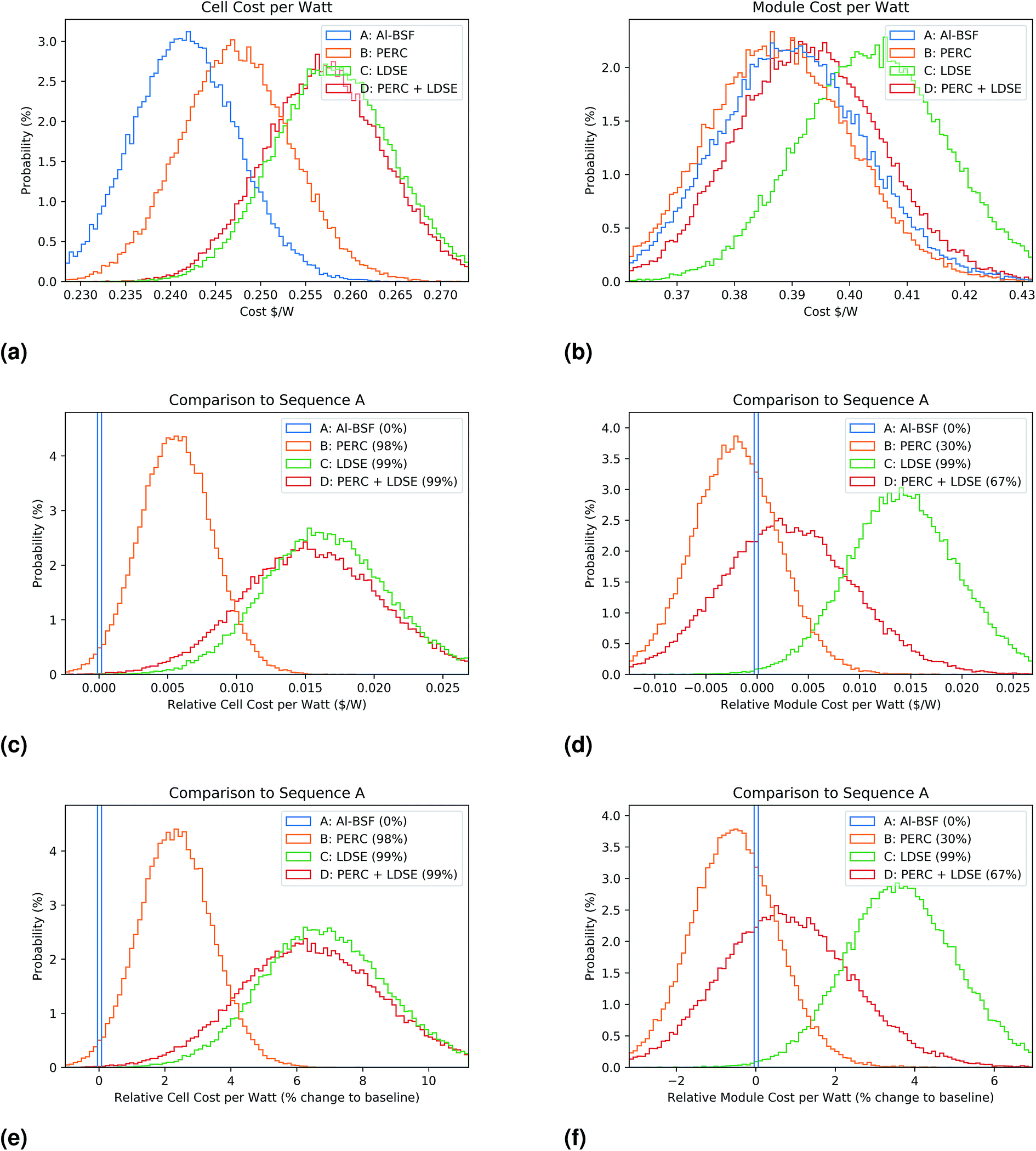 | ||
| Fig. 2 Cost in US$ W−1 comparing sequences A–D. (a), (c) and (e) show the cell cost, (b), (d) and (f) show the module cost. (c) and (d) show the difference in cost compared to the baseline. (e) and (f) show the difference in cost as a percentage change to the baseline. | ||
2.4 Market impact
We have included two types of market impact in this work.The first is the effect of higher power modules on the selling price. As cell efficiencies improve, the power of each module increases without any change in the module area. This is beneficial to the end user, as more electrical energy is generated for the same amount of land, mounting structures and other area related costs. This means that the end user is willing to pay a higher price (in $ W−1) for these higher power modules, though the value of this price gain is uncertain. We have modelled this as a varying PowerPremiumi parameter, expressed in $ per W per additional module Watt. The SellingPriceSeq,i is then calculated using eqn (9), where the BaselineSellingPricei (at the BaselineModulePower of 280W) varies from uncertainty also. To estimate the range of these parameters as shown in Table 2, we have used the historical module wholesale prices for both mono-crystalline Si and multi-crystalline Si modules over the period of 6 months between April and September, 2017.14 In particular we estimate the power premium based on the price differences between the mono and multi modules, as described in more detail in the ESI Section S2.4.†
| SellingPriceSeq,i = BaselineSellingPricei + (ModulePowerSeq,i − 280) × PowerPremiumi | (9) |
The second market effect is the impact on selling price of being “CID-Free”. A module that is free of a particular type of degradation can be expected to produce more electrical power over its lifetime for the same as-produced “sticker” power rating. This benefit is expected to support a higher selling price. We have modelled this effect as a variable CIDFreePremiumi, expressed as a percentage increase in selling price compared to a CID affected module. The customer's view of an acceptable premium would vary depending on the exact installation conditions, as well as the attitude of the customer to risk. For example, degradation may be seen to impact the “bankability”,26 where a customer needs finance to install a large installation, and the lending organisation may be hesitant to lend money where there is significant risk of module degradation. For this study, we have assumed that the CIDFreePremium varies between the ranges shown in Table 2, and this is discussed further in the ESI, Section S2.5.† This factor is used to calculate the SellingPriceCIDPremiumSeq,i in $ W−1 using eqn (10), though this is only applied to sequences where CID is removed by the hydrogenation process.
| SellingPriceCIDPremiumSeq,i = SellingPriceSeq,i × (1 + CIDFreePremiumi) | (10) |
Finally, the MarginSeq,i in $ per module can be calculated from eqn (11), being the figure of merit in comparing the sequences, as it includes the effects of manufacturing cost, cell and module performance and market factors on the commercial attractiveness of the sequences. We focus on the gross margin, though further analysis can be done to include other overhead costs such as R&D, sales and administration costs, as discussed in the ESI (Section S3.4†). A distribution of margin for sequences A–D is shown in Fig. 3b. The margin can alternatively be calculated with the SellingPriceCIDPremiumSeq,i, depending on the analysis being completed.
| MarginSeq,i = SellingPriceSeq,i − ModuleCostSeq,i | (11) |
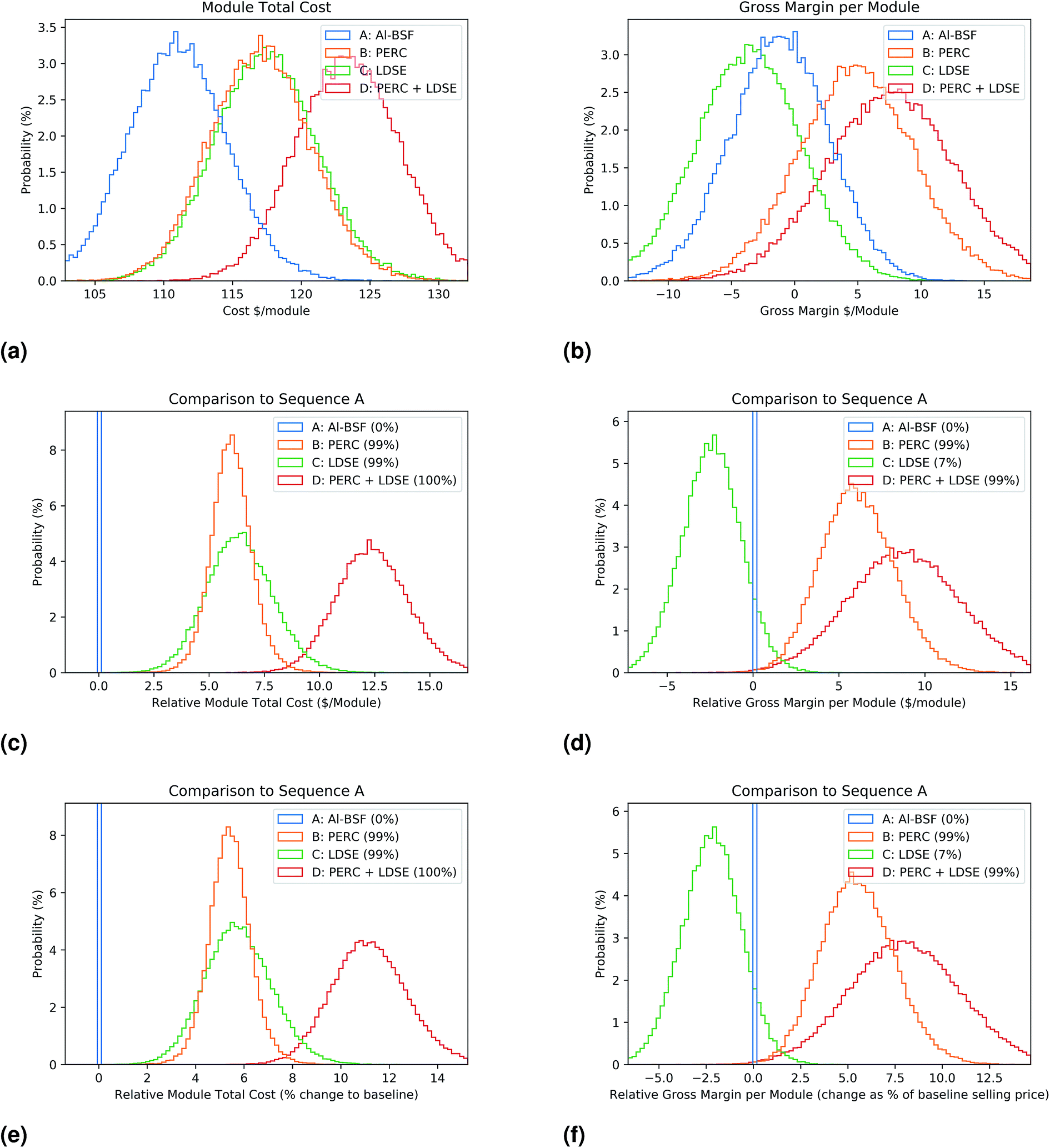 | ||
| Fig. 3 Module cost and margin in US$ per module comparing sequences A–D. Similar to Fig. 2, (a), (c) and (e) show the cost per module and (b), (d) and (f) show the margin per module. For (f), the margin difference to the baseline is expressed as a percentage of the baseline module sales price. | ||
2.5 Simultaneous Monte Carlo analysis
In analysing the results of the cost using uncertainty analysis, we obtain a distribution of cost for each sequence. When comparing two similar process sequences, the differences due to small changes in the sequence can be small. For example, as shown in Fig. 3b, the uncertainty in the various input parameters makes it difficult to determine if one process is better than another.To address this issue, in this work we introduce an additional analytic layer to more accurately compare processes that share a number of common process steps, which we have termed simultaneous Monte Carlo analysis.
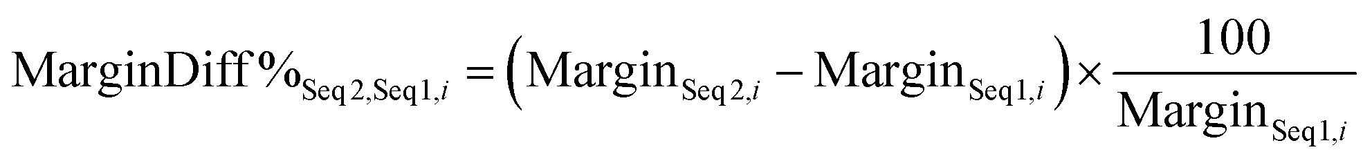
In cases where two sequences share some common process steps we can compare, for example, the margin difference between sequences, as shown in eqn (12). This is calculated for each iteration i, and when the distribution of these i values is plotted, for example in Fig. 3d, the difference between the two sequences becomes clearer. In these plots, the difference parameter for the baseline (i.e. MarginDiffSeq A,Seq A,i) is zero for every iteration, shown by the zero bin (of probability 100%). In the key, the proportion of iterations where the MarginDiff is greater than zero is given, to indicate how likely each sequence is to provide an improved margin compared to the baseline. Similar difference graphs can be generated for different parameters, such as Fig. 2c, 2d and 3c.
| MarginDiffSeq 2,Seq 1,i = MarginSeq 2,i − MarginSeq 1,i | (12) |
To indicate the significance of a difference, it can be expressed as a percentage of the baseline value, such as eqn (13), or as a percentage of another baseline value, such as eqn (14). Some examples of graphs generated using these metrics can be shown in Fig. 3e and f.
 | (13) |
 | (14) |
2.6 Contribution to variance
Once a cost calculation has been completed, with the resultant distribution of calculated cost or margin, we wish to understand which underlying varying parameter is causing the most variation in an output parameter. This allows us to identify the most important factors in a decision to implement a technology change, and can guide future work to refine the cost estimates.To do this, we extended the “Normalised Uncertainty” graph introduced in the previous work,3 where each ProcessCostExMaterialsProc,i and MaterialCostMaterial,Proc,i is categorised by its median contribution to total cost (x axis) and its uncertainty relative to its median cost (y axis). While the normalised uncertainty graph can be used to prioritise process development and cost analysis resources, it only considers the relative importance of contributions to the cost per unit area. In this work, we extend this to a “Contribution to Variance”, which additionally compares the impact of variables related to cell and module performance and market forces.
To complete the contribution to variance analysis, we determine the impact of each varying parameter on a cost result (for example MarginDiff). Input parameters analysed will typically include cost related variables (ProcessCostExMaterialsProc,i and MaterialCostMaterial,Proc,i), performance variables (CellEffSeq,i, CellEffDifferenceSeq1,Seq2,i, CTMPoweri) and market variables (BaselineModulePricei, PowerPremiumi, CIDFreePremiumi). Analysis is completed by calculating the correlation coefficients for each input parameter on the cost result, and then squaring these values to obtain the “Contribution to Variance”, which represents the proportion of uncertainty in the cost result from the uncertainty of each parameter. This method is valid as long as the input parameters are all independent,27 so selection of the input parameters must be done carefully to ensure that there are no inter-relationships between them, and that all significant parameters are included. This can be done in our case since we know the exact model calculations and parameter interactions. A principal component analysis28 has been completed on the inputs, with all the calculated eigenvalues close to 1 confirming parameter independence.
The output of this analysis is an ordered list of input parameters, and the contribution each makes to the uncertainty of the result parameter. An example is shown in Table 4. Once the most important input parameters are identified, it can be helpful to visualise the relationship by plotting the important input parameters against the result parameter, such as in Fig. 5.
3 Results
A summary of all the results of the cost analysis is shown in Table 3, with a closer examination of the sequences described in the following sections.| Seq | Module cost ($ per module) | Cell eff (%) | Cell cost ($ W−1) | Module cost ($ W−1) | Margin ($ per module) | Margin (with CID premium) ($ per module) |
|---|---|---|---|---|---|---|
| A | 111 (106–116) | 20.0 (19.9–20.1) | 0.244 (0.237–0.252) | 0.39 (0.374–0.406) | −1.2 (−6.3–3.7) | −1.2 (−6.3–3.7) |
| B | 117 (112–122) | 21.2 (21.0–21.4) | 0.25 (0.242–0.259) | 0.388 (0.372–0.404) | 4.9 (−0.9–10.6) | 4.9 (−0.9–10.6) |
| C | 117 (113–122) | 20.4 (20.3–20.5) | 0.261 (0.252–0.27) | 0.404 (0.388–0.421) | −3.6 (−9.0–1.6) | −3.6 (−9.0–1.6) |
| D | 123 (119–128) | 22.1 (21.8–22.3) | 0.26 (0.251–0.269) | 0.393 (0.377–0.409) | 7.6 (1.1–14.1) | 7.6 (1.1–14.1) |
| E | 118 (113–122) | 21.4 (21.2–21.6) | 0.249 (0.241–0.258) | 0.386 (0.37–0.402) | 6.4 (0.5–12.4) | 7.8 (1.8–13.9) |
| F | 118 (113–122) | 21.4 (21.2–21.6) | 0.249 (0.241–0.258) | 0.386 (0.37–0.402) | 6.4 (0.4–12.3) | 7.8 (1.7–13.9) |
| G | 117 (113–122) | 21.4 (21.2–21.6) | 0.248 (0.24–0.257) | 0.385 (0.369–0.401) | 6.7 (0.8–12.7) | 8.2 (2.1–14.3) |
3.1 Cost/benefit analysis of improvements to the silicon cell design
The first analysis considers the benefit of one or both of the LDSE and PERC processes to the standard Al-BSF sequence, as described in Section 1. Sequences A–D are the four combinations of these sequences. The distribution of cell and module cost in US$ W−1 is shown in Fig. 2, and the cost and margin per module in US$ per module is shown in Fig. 3. In both of these figures, we use simultaneous Monte Carlo analysis to plot the difference between each sequence and the baseline sequence A, making differences between the sequences more obvious. In this and other distribution figures within the paper, we have used 100 bins on the x-axis, whose width varies depending on the parameter being analysed and its uncertainty range. The y-axis shows the probability of values in each bin.Fig. 3a, c and e show the distribution of ModuleCostSeq,i in $ per module for sequences A–D. We can see that changing from Seq A to Seq B increases the per unit area manufacturing cost by about 5%. This is because of the need to add the deposition of the rear passivation layers, and then the formation of laser openings in these layers. Similarly, changing from Seq A to Seq C increases the manufacturing cost by a similar amount per unit area because of the added thermal oxide layer, dopant application and laser processing. Partially off-setting these increased costs, Seq C replaces the expensive front Ag screen print pastes with plating. Seq D incorporates the new processes on both the front and rear of the cell has the highest per unit area cost, approximately 11% higher than the baseline sequence.
Fig. 2 has similar graphs showing the impact of improved cell and module efficiency on the distribution of CellCostPerWattSeq,i and ModuleCostPerWattSeq,i. At the cell level, the higher efficiency sequences improve $ W−1 cost, and this effect is further enhanced at the module level, where sequence B (PERC) is likely to be lower cost than the baseline sequence A (Al-BSF) by about 0.5%.
Once the PowerPremiumi is taken into account to calculate the ModuleMarginSeq,i, as shown in Fig. 3b, d and f, it is now highly likely that sequence B (PERC) is more commercially attractive compared to the baseline sequence A (Al-BSF), with a predicted 5% improvement in margin on sales, but sequence C (LDSE) is not, despite its higher cell and module efficiency. Sequence D (LDSE + PERC) on average shows an small improved margin compared to sequence B. In the ESI (Section S3.4†) we compare these results with reported industry gross margin and operating margin data, showing that they are in the same range as at mid 2017.
If a manufacturer is considering changing a process sequence, there is substantial investment required, as well as increased risk. Such risk includes short term issues such as lost or reduced production time as a new process is optimised. It can also include long term issues such as the need to invest continually in the R&D of a new technology to ensure that it keeps up with improvements in the standard technology. Therefore the improvement predicted in an analysis like this must be substantial to account for this risk. Fig. 3e and f, which indicate the percentage changes in module cost and module margin are helpful to show the significance of any improvement. We would expect that the scale of improvement required for a company to consider a new technology would not be the same in every case, being balanced by many factors, such as the amount of investment required to implement the technology, and the risk that a performance or market improvement is not forthcoming.
We now focus our attention in particular on comparing sequence B to sequence D, as we seek to answer the question of whether LDSE when added to PERC could be a viable improvement for the industry. We first plot the distribution of MarginDiffSeqD,SeqB,i, as shown in Fig. 4a (as $ per module) and Fig. 4b (as % of sales price). From this, we can see that sequence D is very likely to provide a better margin than sequence B, but with a median benefit of 2% of sales, much smaller than the 5% of sales predicted when moving from Seq A to Seq B. In order to identify the most critical parameters affecting this conclusion, we complete a contribution to variance analysis on the MarginDiffSeq D,Seq B,i parameter, as shown in Table 4. This reveals that the uncertainty in the cell efficiency boost for this process is most important, followed by the value of the price premium we can expect for higher power modules and any yield differences between the sequences. After this, the cost of some of the processes and materials are important. We can see the impact of some of these uncertainties graphically as shown in Fig. 5, where the difference in margin between sequence D and B is plotted against the four most significant of these variables. A linear regression and the correlation co-efficient are displayed on each graph to show the impact of each variable. This analysis helps us test the impact of our assumptions and focus our research on the most significant factors. If we believe a cell efficiency boost near 0.9%abs is likely, or can be proven for this technology (and can be maintained over time), the PowerPremium assumed is reasonable, the process can maintain a yield similar to that of the standard cells and the 2% increase in margin is worth the risk, then the technology would be worth pursuing. Conversely, if the decision maker is of the belief that a power premium is unlikely to be maintained into the future, that the standard PERC technology will improve such that the LDSE benefit is diminished, or the margin benefit is not worth the risk, then the conclusion may be that it is not worth following this path.
 | ||
| Fig. 4 Margin of sequence D relative to sequence B. (a) shows the relative margin in $ per module (b) as a percentage of baseline module sales price. | ||
| Parameter | Unit | Uncertainty range | Contrib. to variance in MarginDiffSeq D,Seq B (%) |
|---|---|---|---|
| Efficiency difference | %abs | 0.7–1.0 | 33 |
| Power premium | c per W per module W | 0.08–0.13 | 14 |
| Yield difference | % | −1.09–1.08 | 14 |
| Ag plating solution | $ m−2 | 0.56–1.7 | 12 |
| Plating tool | $ m−2 | 1.37–2.4 | 10 |
| Front Ag paste | $ m−2 | 1.19–2.2 | 9 |
| Doping laser | $ m−2 | 0.82–1.45 | 4 |
| All other | 4 |
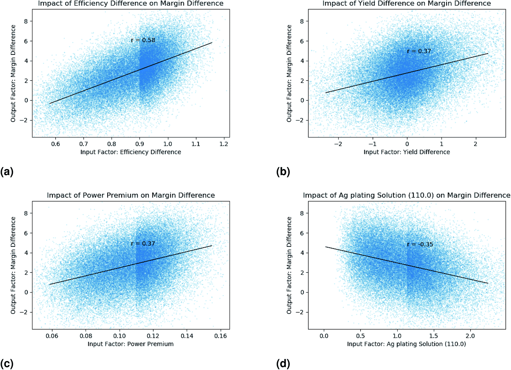 | ||
| Fig. 5 Scatter plots of key variables (a) efficiency difference, (b) yield difference, (c) Power premium and (d) the cost of the plating solution material, showing their impact on the margin improvement of sequence D compared to sequence B. The visible vertical lines in (a), (b) and (d) are due to a discontinuities in the distribution of parameters that can occur at the median value when using half-log-normal distributions, as explained in the ESI S3.1.† | ||
In the ESI,† we discuss the benefit of conducting the contribution to variance on the ModuleMarginDiff (as we have done here) rather than the ModuleMarginSeq,i (Section S4.1†).
3.2 Cost/benefit analysis of advanced hydrogenation
In this second application we compare three implementations of hydrogenation of PERC cells to standard PERC cells (see Section 1). In Fig. 6 we see that the increase in manufacturing cost from implementing any of the hydrogenation processes on a PERC baseline leads to approx 0.5% higher costs per module (Fig. 6a) and approx 0.5% lower cost per Watt (Fig. 6b). On this basis alone, a manufacturer may not be motivated to take on the risk of a process change. However, when we take into account the expected PowerPremiumi and calculate the margin (Fig. 6c), the hydrogenation sequences are each more than 90% likely to provide an improved margin, estimated to be more than 1%. If we also include the additional impact of the CIDFreePremiumi (Fig. 6d), the estimated margin improvement increases to over 2%. Whilst this is a similar improvement to the comparison between Seq B and Seq D, the relatively low risk of implementing this technology (a single added process step) makes this change much more attractive from a risk reward standpoint.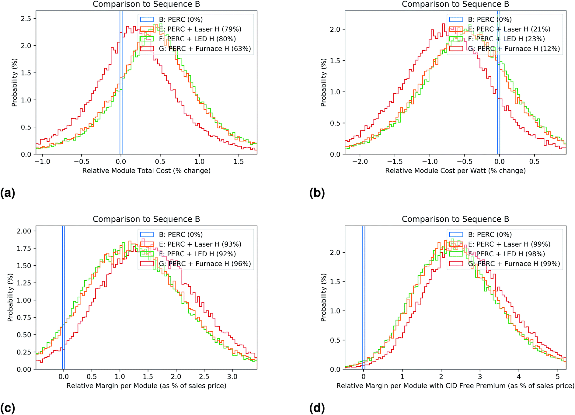 | ||
| Fig. 6 Cost distribution of the various hydrogenation processes compared as a percentage to the baseline Seq B in (a) module cost per unit area (b) module cost per Watt, (c) margin per module and (d) margin per module assuming the variable price premium for being CID-Free. | ||
Again, applying the contribution to variance analysis to MarginDiffSeq E,Seq B,i, we can see the main contributors to uncertainty in Table 5 and Fig. S6.† The uncertain range of the CIDFreePremiumi, as-produced efficiency gain and production yield are all very important, dominating all other factors. This is in important result as it shows that the CID-Free market factor is just as important as the technical improvements in assessing the benefit of this technology, and should be considered by decision makers contemplating implementing this technology.
| Parameter | Unit | Uncertainty range | Contrib. to variance of MarginDiffCIDSeq B,Seq E (%) |
|---|---|---|---|
| CID-free premium | % rel | 0.5–2.0 | 34 |
| Efficiency difference | %abs | 0.1–0.3 | 34 |
| Yield difference | % | −1.09–1.08 | 29 |
| Power premium | c per W per module W | 0.08–0.13 | 2 |
| All other | 1 |
In the ESI† we show extended results comparing the three alternative advanced hydrogenation sequences (Section S4.2†), to see which specific implementation would be most advantageous. We see that the performance benefit of each sequence (as-produced efficiency boost and yield) dominate over the cost of implementing each alternative. From this we conclude that production tests comparing the performance of each method are more critical than the cost per wafer comparison.
3.3 Future directions and conclusions
An extension to a cost and uncertainty method has been outlined which adds the impact and uncertainty of module performance and market parameters to assess the commercial potential of a technology, taking into account cost, performance and market factors simultaneously. The method's utility has been demonstrated by applying it to Al-BSF, PERC, LDSE, PERC + LDSE and advanced hydrogenation c-Si cell fabrication sequences. Through the use of simultaneous Monte Carlo analysis, small differences between sequences can be resolved, and with the contribution to variance analysis, the most important performance, market and process cost components that impact the commercialisation potential of each new technology can be identified.The analysis indicates that the PERC technology (compared to Al-BSF), while increasing manufacturing costs by >5% per module, can provide >5% improvement to the manufacturer's margin due to improved cell and module efficiency and therefore higher module prices. This is consistent with the industry trend of increasing PERC market share, though this advantage could be nullified if a technology improvement arrives that allows Al-BSF to close this performance gap.
LDSE technology, when applied as an addition to the PERC process, has potential with an expected improvement in margin >2%. The critical parameters to this analysis are the improved cell efficiency of 0.9%abs and high production yield. The specific costs of the processes such as the laser doping and plating are much less important. This suggests that researchers should currently focus primarily on demonstrating the cell performance with high reliability. If this can be done, such that the expected performance and yield is proven, then additional focus on the cost of each process step would become more important to any further investment decisions.
For the advanced hydrogenation technology, the cost of implementing the process is similarly of low importance at this stage. In this case, the technical improvement of an as-produced efficiency gain, combined with a high yield is important, but of similar importance is the market value of being “CID-Free”. If this results in a 0.5% price premium at the module level, in combination with the assumed 0.2%abs as-produced efficiency without negatively impacting the production yield, this process is expected to improve margin by >2%. This benefit is particularly attractive compared to PERC + LDSE because it only requires investment in a single additional process step, which reduces the risk implementing the new process in production. An important implication for researchers is to understand that this technology depends on market acceptance and valuation of its improved degradation, something that technologists can easily neglect.
These techno-economic analyses, with the estimated commercial improvements and identification of critical cost, performance and market factors can be used to inform research and investment directions for promising near-commercial c-Si PV technologies.
Conflicts of interest
There are no conflicts of interest to declare.Acknowledgements
Alison Ciesla, Brett Hallam and Malcolm Abbott for their guidance in understanding the LDSE and Advanced Hydrogenation processes. The Australian Centre for Advanced Photovoltaics (ACAP) encompasses the Australian-based activities of the Australia-US Institute for Advanced Photovoltaics (AUSIAPV) and is supported by the Australian Government through the Australian Renewable Energy Agency (ARENA). The views expressed herein are not necessarily the views of the Australian Government, and the Australian Government does not accept responsibility for any information or advice contained herein. N. L. Chang is supported by an Australian Government Research Training Program Scholarship.References
- Annex G., Technology Readiness Levels (CE), http://ec.europa.eu/research/participants/data/ref/h2020/other/wp/2016-2017/annexes/h2020-wp1617-annex-ga_en.pdf, accessed: 2017-04-18.
- Technology Readiness Assessment Guide (DOE), https://www.directives.doe.gov/directives-documents/400-series/0413.3-EGuide-04a, accessed: 2017-04-18.
- N. L. Chang, A. W. Ho-Baillie, P. A. Basore, T. L. Young, R. Evans and R. J. Egan, A manufacturing cost estimation method with uncertainty analysis and its application to perovskite on glass photovoltaic modules, Prog. Photovoltaics, 2017, 25(5), 390–405 Search PubMed.
- ITRPV Eighth Edition 2017, http://www.itrpv.net/.cm4all/iproc.php/ITRPV%20Eighth%20Edition%202017.pdf?cdp=a, accessed: 2017-05-01.
- M. A. Green, The passivated emitter and rear cell (PERC): from conception to mass production, Sol. Energy Mater. Sol. Cells, 2015, 143, 190–197 CrossRef CAS.
- Z. Shi, S. Wenham and J. Ji, Mass production of the innovative PLUTO solar cell technology, Photovoltaic Specialists Conference (PVSC), 2009 34th IEEE, IEEE, 2009, pp. 001922–001926 Search PubMed.
- A. Ciesla, R. Chen, S. Wang, J. Ji, Z. Shi, L. Mai, C. Chan, B. Hallam, C. Chong, S. Wenham and M. Green, High-voltage p-type PERC solar cells with anchored plating and hydrogenation, Progress in Photovoltaics: Research and Applications, 2018, DOI:10.1002/pip.2986.
- A. Wenham, C. M. Chong, S. Wang, R. Chen, J. Ji, Z. Shi, L. Mai, A. Sugianto, M. Abbott and S. Wenham, et al., Copper plated contacts for large-scale manufacturing. Photovoltaic Specialists Conference (PVSC), 2016 IEEE 43rd, IEEE, 2016, pp. 2990–2993 Search PubMed.
- B. Hallam, C. Chan, D. Payne, D. Lausch, M. Glaeser, M. Abbott and S. Wenham, Techniques for mitigating light-induced degradation (LID) in commercial silicon solar cells, Photovoltaics International, 2016, 33, 37–46 Search PubMed.
- B. J. Hallam, C. E. Chan, R. Chen, S. Wang, J. Ji, L. Mai, M. D. Abbott, D. N. R. Payne, M. Kim, D. Chen, C. Chong and S. R. Wenham, Rapid mitigation of carrier-induced degradation in commercial silicon solar cells, Jpn. J. Appl. Phys., 2017, 56(8S2), 08MB13 CrossRef.
- K. Lee, M. Kim, J. K. Lim, J. H. Ahn, M. I. Hwang and E. C. Cho, Natural Recovery From Lid: Regeneration Under Field Conditions?, European Photovoltaic Solar Energy Conference (EUPVSEC), 31st. EUPVSEC, 2015, pp. 1835–1837 Search PubMed.
- B. Hallam, J. Bilbao, D. Payne, C. Chan, M. Kim, D. Chen, N. Gorman, M. Abbott and S. Wenham, Modelling the Long-Term Behaviour of Boron-Oxygen Defect Passivation in the Field Using Typical Meteorological Year Data (TMY2), European Photovoltaic Solar Energy Conference (EUPVSEC), 32nd. EUPVSEC, 2016, pp. 555–559 Search PubMed.
- Jinko Solar Q2 2017 Result, http://phx.corporate-ir.net/External.File?item=UGFyZW50SUQ9Njc4OTk1fENoaWxkSUQ9Mzg4MDY0fFR5cGU9MQ==%26t=1, accessed: 2017-09-13.
- EnergyTrend Website, http://pv.energytrend.com/pricequotes.html, Data from April 2017 until September 2017.
- A. C. Goodrich, D. M. Powell, T. L. James, M. Woodhouse and T. Buonassisi, Assessing the drivers of regional trends in solar photovoltaic manufacturing, Energy Environ. Sci., 2013, 6(10), 2811–2821 Search PubMed.
- A. Goodrich, P. Hacke, Q. Wang, B. Sopori, R. Margolis, T. L. James and M. Woodhouse, A wafer-based monocrystalline silicon photovoltaics road map: utilizing known technology improvement opportunities for further reductions in manufacturing costs, Sol. Energy Mater. Sol. Cells, 2013, 114, 110–135 CrossRef CAS.
- D. M. Powell, M. T. Winkler, H. Choi, C. B. Simmons, D. B. Needleman and T. Buonassisi, Crystalline silicon photovoltaics: a cost analysis framework for determining technology pathways to reach baseload electricity costs, Energy Environ. Sci., 2012, 5(3), 5874–5883 Search PubMed.
- D. M. Powell, M. T. Winkler, A. Goodrich and T. Buonassisi, Modeling the cost and minimum sustainable price of crystalline silicon photovoltaic manufacturing in the United States, IEEE Journal of Photovoltaics, 2013, 3(2), 662–668 CrossRef.
- D. M. Powell, R. Fu, K. Horowitz, P. A. Basore, M. Woodhouse and T. Buonassisi, The capital intensity of photovoltaics manufacturing: barrier to scale and opportunity for innovation, Energy Environ. Sci., 2015, 8(12), 3395–3408 Search PubMed.
- M. Woodhouse, D. Feldman, R. Fu, A. Ramdas, R. Margolis. Economic Factors of Production Affecting Current and Future Crystalline Silicon Photovoltaic Manufacturing Costs and Sustainable Pricing, Paper Under Preparation, data taken from May 2017.
- M. Edwards, Efficiencies of 22% at low cost: the future of mass-produced laser-doped selective emitter solar cells, Photovoltaics International, 2011, 10, 72–78 Search PubMed.
- N. L. Chang, A. W. Y. Ho-Baillie, D. Vak, M. Gao, M. A. Green and R. J. Egan, Manufacturing cost and market potential analysis of demonstrated roll-to-roll perovskite photovoltaic cell processes, Sol. Energy Mater. Sol. Cells, 2018, 174, 314–324 CrossRef CAS.
- Personal Communication – Hydrogenation Group, UNSW, Dates: 2016-Dec to 2017-Aug.
- Personal Communication – Sunrise, Dates: 2017-Feb.
- I. Haedrich, U. Eitner, M. Wiese and H. Wirth, Unified methodology for determining CTM ratios: systematic prediction of module power, Sol. Energy Mater. Sol. Cells, 2014, 131, 14–23 CrossRef CAS.
- Solar Bankability Report, http://www.solarbankability.org/fileadmin/sites/www/files/documents/Solar_Bankability_Final_Report.pdf, accessed: 2017-08-30.
- D. R. Seibold and R. D. McPhee, Commonality analysis: a method for decomposing explained variance in multiple regression analyses, Human Communication Research, 1979, 5(4), 355–365 CrossRef.
- J. E. Jackson, A user's guide to principal components, vol. 587, John Wiley & Sons, 1991 Search PubMed.
Footnote |
| † Electronic supplementary information (ESI) available. See DOI: 10.1039/c8se00047f |
| This journal is © The Royal Society of Chemistry 2018 |