
Performance bounds and perspective for hybrid solar photovoltaic/thermal electricity-generation strategies†
A.
Vossier
 *a,
J.
Zeitouny
ab,
E. A.
Katz
c,
A.
Dollet
a,
G.
Flamant
a and
J. M.
Gordon
c
*a,
J.
Zeitouny
ab,
E. A.
Katz
c,
A.
Dollet
a,
G.
Flamant
a and
J. M.
Gordon
c
aLaboratoire Procédés, Matériaux et Energie Solaire (PROMES)-CNRS, 7 Rue du Four Solaire, 66120 Odeillo, France. E-mail: alexis.vossier@promes.cnrs.fr
bUniversité de Perpignan Via Domitia (UPVD), 52 Avenue Paul Alduy, 66100 Perpignan, France
cDepartment of Solar Energy and Environmental Physics, Jacob Blaustein Institutes for Desert Research, Ben-Gurion University of the Negev, Sede Boqer Campus, 8499000, Israel
First published on 18th July 2018
Abstract
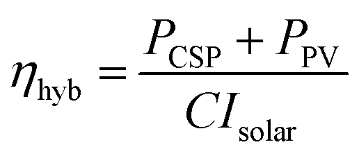
Hybrid solar photovoltaic (PV)/thermal power systems offer the possibility of dispatchable, affordable and efficient solar electricity production – the type of transformative innovation needed for solar cell devices to realize high grid penetration. The PV sub-system enjoys high efficiency, and the thermal sub-system can ensure uninterrupted power delivery via backup gas heating and/or multi-hour thermal storage. However, elucidation of the basic performance bounds, and the quantitative perspective required for judging the leading hybrid strategies relative to one another, as well as relative to the existing alternative of autonomous photovoltaic and solar thermal power systems, have remained incomplete. A more thorough and basic evaluation of the performance of the assorted combinations of PV and solar thermal sub-systems over a wider range of possible operating conditions than regarded previously is presented here. This involves analysis of the most fundamental processes limiting system efficiency, tempered by the realities of current and foreseeable PV and thermal technologies. The 3 leading hybrid strategies are: (1) concentrated solar beam radiation irradiating an integrated PV–thermal receiver, with the unique advantage of recuperating PV thermalization losses as heat delivered to the thermal receiver, thereby contributing to driving the turbine, (2) the spectral splitting of concentrated solar beam radiation, with sub-bandgap photons directed to a thermal receiver and the rest to concentrator PV cells, and (3) nominally 1 sun PV cells performing double duty as both a direct converter and as a spectrum-splitting reflector that concentrates sub-bandgap photons onto a thermal receiver. The two figures of merit appraised are: (a) the solar-to-electricity conversion efficiency, and (b) the share between thermal and PV electricity production.
Introduction
Hybrid solar electricity-generation systems that integrate photovoltaic (PV) with thermal concentrated solar power (CSP) sub-systems have the potential virtues of being dispatchable, economically competitive, and offering uninterrupted power production (dispatchability refers to the ability to turn electricity production on or off and to moderate instantaneous power according to demand). In its Advanced Research Projects Agency-Energy program, the U.S. Department of Energy has labelled this research direction as having the potential to provide transformative innovations via which solar electricity generation can achieve high grid penetration.1The PV sub-system – with the option of adopting concentrator photovoltaics (CPV) – enjoys high efficiency and low cost, but with intermittent power delivery due to the irregular nature of the solar input. CSP surmounts the latter problem via the introduction of gas-fired backup heating and/or high-temperature multi-hour thermal storage, but at higher cost.
Nevertheless, evaluations of the power generation efficiency bounds for the foremost approaches (Fig. 1), as well as comparisons against the existing paradigm of totally separate PV and solar thermal power systems, have remained incomplete, and are addressed in depth in this paper.
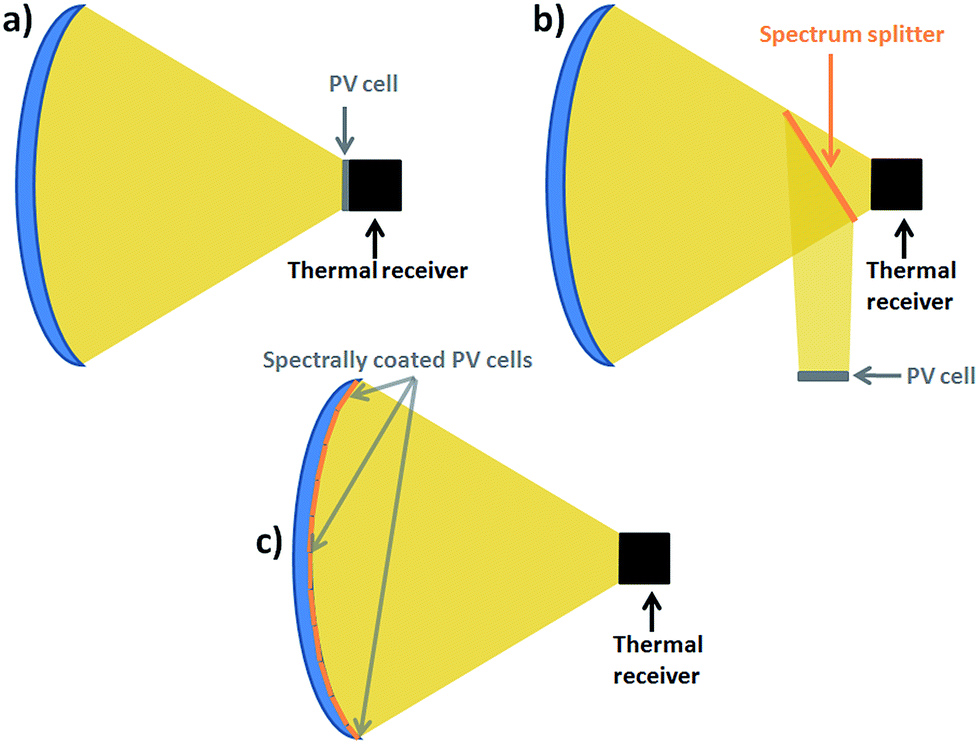 | ||
| Fig. 1 Schematic of the 3 PV–CSP hybrid strategies investigated: (a) concentrated solar power irradiates an integrated high-temperature PV–thermal absorber. (b) Spectrum-splitting, whereby concentrated solar beam radiation irradiates separate PV and thermal receivers. The generic spectrum splitter indicates the selective transmission and reflection of a single or multiple spectral cutoffs. (c) 1 sun cell. The concentrator surface comprised by non-concentrator PV cells reflects the part of the solar spectrum not absorbed by the cells onto a thermal receiver. | ||
Specific aspects of this broader perspective include (1) high-concentration point-focus systems (concentration ratios of order 103) where collector heat losses are rendered negligible relative to optical gains; (2) the potential of properly crafted PV cells to function efficiently at temperatures upward of ∼400 °C, with the recuperation of thermalization losses in an integrated-receiver approach more than compensating for the loss of PV efficiency at these elevated temperatures; and (3) showing that the conversion efficiency of even the best hybrid strategies can only modestly exceed those of the obvious alternative of totally autonomous PV and CSP systems.
The first strategy – the “high-temperature cell” approach (Fig. 1a) – uses PV cells as the top tier of an integrated receiver, thermally bonded to a thermal receiver beneath it.2,3 The integrated PV–thermal receiver operates at the high temperatures required to drive efficient steam turbines. The cell materials, architecture and optical concentration need to be selected so as to maintain an acceptably small penalty for high-temperature PV operation. An energetically optimal operating temperature stems from the tradeoff that higher temperatures: (1) diminish PV efficiency (compounded by absorber heat loss increasing with temperature), but (2) can increase turbine efficiency. The main advantage of this strategy is exploiting the energy from PV thermalization that is otherwise rejected to the environment – and which commonly constitutes a non-negligible fraction of the collectible solar radiation – as part of the thermal sub-system's power production. Recent encouraging preliminary experimental evidence shows that PV devices can function at temperatures as high as 400–600 °C without considerable device degradation, under optical concentration values up to 1500 suns (ref. 4–6) (1 sun refers to the peak terrestrial solar irradiance of 1 mW mm−2). The first junctions explored were InxGa1−xN, GaAs and AlxGayIn1−x−yP, and research efforts to identify superior candidates are underway.5,6
The second strategy is spectrum splitting (Fig. 1b), which separates the PV and thermal receivers. The higher-energy photons of concentrated sunlight are diverted to PV cells and the rest to a thermal absorber. The methods for realizing spectral separation include the use of a semiconductor-doped glass in combination with an appropriate heat transfer fluid,7,8 the use of a secondary concentrator acting as a spectrum splitter,9–11 and the implementation of a spectrally selective light pipe.12 In each case, decoupling and independently operating the PV and thermal converters enhances system versatility.2,13
In the third “1 sun cell” strategy (Fig. 1c), the contour of a reflective concentrator is covered with PV cells, whereby sub-bandgap photons are concentrated onto a thermal absorber.14–16 Its principal advantage is not sacrificing the diffuse component of incident solar radiation. In particular, as a consequence of the fundamental principle that diffuse radiation cannot be concentrated,17 the first two strategies (Fig. 1a and b), as well as the thermal receiver in the 1 sun-cell approach (Fig. 1c), are intrinsically limited to the collection of beam radiation only.
The second and third strategies admit the possibility of splitting the spectrum into multiple (rather than just two) bands toward enhancing system efficiency, e.g., directing the highest-energy part of the solar spectrum, for which conventional single-junction PV cells often exhibit a poor external quantum efficiency, to the thermal absorber (noted in Table 1 and evaluated below). The practical challenges subsume finding feasible optical surfaces that efficiently divide the spectrum as needed, and, for the second strategy, exhibiting resilience under concentrated sunlight.
| High-temp. PV | Spectrum-splitting | 1 sun cell | |
|---|---|---|---|
| PV cell temp. | T CSP (393–550 °C) | T a (25 °C) | T a (25 °C) |
| Concentration | For both PV and CSP: 25–50 for line-focus. 1000–2000 for point-focus | For both PV and CSP: 25–50 for line-focus. 1000–2000 for point-focus | 1 sun for PV. For CSP: 25–50 for line-focus. 1000–2000 for point-focus |
| Collectible radiation | Direct | Direct | Global for PV. Direct for CSP |
| — | Option of also directing the highest-energy photons to the thermal absorber | Option of also directing the highest-energy photons to the thermal absorber |
Most prior studies of hybrid solar power systems have been confined to line-focus concentrators, and principally to the spectrum-splitting approach.2–16 Even investigations of multiple hybrid strategies2,13,14 invoked a sufficiently narrow range of operating conditions that comparisons among them – as well as comparisons against the evident existing alternative of completely separate PV and CSP power plants – have remained equivocal. To our knowledge, this is the first evaluation providing a wide-ranging quantitative perspective on the efficiency optimization.
The evaluations below elucidate the higher overall system efficiencies attainable with point-focus concentrators, which also engender the added flexibility of advancing to higher concentration and higher temperature should there be substantial future advances in device physics and turbine technology.
Our analysis of efficiency losses is restricted to those inherent to the PV and thermal converters, in contrast to the losses associated with the particular concentrators or optical systems within which the solar converters are deployed. The reason is that the same types of converters can equally well be installed in optics that introduce their own material-specific optical losses and span a wide range of concentration, conflated with field layouts that incur varying degrees of geometric losses in collectible radiation due to shading and cosine effects. We address these issues below, but treat them as distinct from the conversion losses intrinsic to the converters themselves.
Model
PV efficiency ηPV is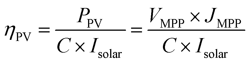 | (1) |
Toward establishing upper bounds for system performance, ηPV was initially evaluated in the radiative limit.18–20 This means no non-radiative recombination or other electrical losses (including the effect of series resistance), one electron–hole pair generated per absorbed photon, and no absorption of photons with energies below the bandgap Eg. PV modelling is detailed in the ESI.†
At the temperature and concentration levels considered here, heat losses are dominated by thermal radiation, for which the emitted power density Prad (per absorber area) is
| Prad = εσ(T4 − Ta4) | (2) |
The corresponding convective heat loss density Pconv (per absorber area) can be estimated as
| Pconv = h(T − Ta) | (3) |
Heat loss density per collection aperture area is Ploss/C.
Large-scale CSP line-focus systems typically comprise parabolic trough mirrors, with C ≈ 25 (C is mainly limited by commercially achievable, affordable optical tolerances). Selectively coated receivers reach ε ≈ 0.1 for T ≈ 350–550 °C.24 Toward accommodating realistic future advances in optical design and precision, our sensitivity studies cover C = 25–50.
Large-scale point-focus systems have already reached C ≈ 1000 for commercially realized, economic optical tolerances. To account for feasible future improvements, our sensitivity study covers C = 1000–2000. Because the heat loss per collector aperture area is only of the order of a percent at such high C values, and due to the instability of candidate selective coatings for the non-evacuated point-focus receivers, selective coatings are unwarranted. So for a liberal estimate of heat loss, we adopt ε = 1 (blackbody emission) in eqn (2).
While our aim is establishing fundamental performance bounds, they are tempered by the realities of thermal turbines, collector heat transfer fluids and solid-state devices. In particular, because point-focus solar concentrators can generate considerably higher temperatures at high collection efficiency, the reason for not analyzing temperatures above the maximum value considered here needs to be addressed.
In principle, futuristic turbines might accommodate higher temperatures than those examined here. Yet it is conventional steam turbines that have exclusively been used in CSP systems, as well as for CSP plants currently under construction. For reasons related both to the rapid rise of steam pressure with temperature, and to the material integrity of turbine blades, even steam turbines in standard fossil-fuel-fired power plants have been restricted to inlet temperatures below ∼560 °C.
The collector heat transfer fluid in basically most of all large-scale CSP plants (based on parabolic trough technology) has been an oil that degrades above ∼400 °C. For this reason, maximum collector outlet temperatures have not been allowed to exceed ∼393 °C. And in recent CSP pilot plants with molten salt collector heat transfer fluids,13,21,25–27 the stability of the best viable salt mixtures discovered to date limits maximum temperatures to ∼550 °C. The solar collector temperatures considered here are commensurately limited.
In addition, while there are preliminary encouraging data for the stability of candidate PV cells up to 600 °C, there appear to be no studies at higher temperatures. The absence of evidence that all cell components could withstand higher temperatures over exposure periods of years, and the concern about possible degradation of PV cells at such ultra-high temperatures, for example by enhanced metal diffusion at the p–n junctions, provide an additional incentive to constrain analyses to T < 600 °C.
The results presented below do not include CSP collector outlet temperatures lower than ∼390 °C because the corresponding low thermal turbine conversion efficiencies either unduly reduce overall system efficiency, or result in an energetically optimal system that is CPV only.
Regarding turbine performance, we note that the measured efficiency of the steam turbines installed in a broad range of large-scale CSP systems has reached about 2/3 of the Carnot limit.1,2,28 The efficiency of the thermal converter can thus be expressed as
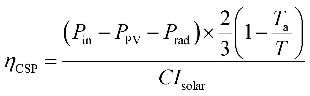 | (4) |
 | (5) |
The following additional approximations were made:
(1) Cell temperature equals ambient temperature in both the “1 sun” and the “spectrum-splitting” strategy, whereas the cell temperature equals the thermal receiver temperature in the “high-temperature” approach.
(2) Optical losses from the concentrator and the spectral splitter, as well as geometric losses for a particular field layout, are discounted (elaborated below).
(3) The ratio of normal global to normal direct solar radiation was estimated as 1.3, its annual-average value based on data from 5 high-insolation locations in the U.S.29
The efficiency of both the “spectrum-splitting” and the “high-temperature cell” approach may be improved using multi-junction cells.13 However, economic considerations currently preclude their use in the 1 sun approach. This prompted limiting our consideration to single-junction cells, for a self-consistent comparison among the 3 strategies.
Operating conditions are summarized in Table 1.
Results
Sensitivity to temperature and concentration
The sensitivity of maximum attainable efficiency to C and TCSP is summarized in Table 2, including the associated PV fraction. The results reflect both (a) the extent to which the higher turbine efficiency at higher temperature is counterbalanced by the concurrent decrease in PV efficiency, as well as (b) the degree to which higher C increases PV efficiency and decreases absorber heat loss.| Conc. | Hybrid efficiency at | PV fraction at | ||
|---|---|---|---|---|
| 393 °C | 550 °C | 393 °C | 550 °C | |
![[thin space (1/6-em)]](https://www.rsc.org/images/entities/char_2009.gif) |
||||
| High-temperature cell strategy | ||||
| Line focus | ||||
| 25 | 0.350 | 0.286 | 0.525 | 0.508 |
| 50 | 0.378 | 0.351 | 0.512 | 0.449 |
| Point focus | ||||
| 1000 | 0.423 (0.385) | 0.430 | 0.567 | 0.485 |
| 2000 | 0.433 | 0.441 | 0.584 | 0.502 |
|
||||
| Spectrum-splitting strategy | ||||
| Line focus | ||||
| 25 | 0.332 | 0.279 | 0.722 | 0.801 |
| 50 | 0.356 | 0.340 | 0.682 | 0.714 |
| Point focus | ||||
| 1000 | 0.390 (0.379) | 0.403 | 0.757 | 0.637 |
| 2000 | 0.396 | 0.411 | 0.756 | 0.680 |
|
||||
| 1 sun cell strategy | ||||
| Line focus | ||||
| 25 | 0.386 | 0.331 | 0.804 | 0.882 |
| 50 | 0.407 | 0.389 | 0.762 | 0.750 |
| Point focus | ||||
| 1000 | 0.424 (0.391) | 0.438 | 0.731 | 0.667 |
| 2000 | 0.426 | 0.443 | 0.728 | 0.660 |
In the sub-sections that follow, for economy of presentation, we restrict detailed evaluations to the promising scenario of C = 1000 and TCSP = 393 °C – promising because higher concentration and higher temperature offer little improvement, with the greatest efficiency enhancement (for the high-temperature cell approach) relative to the corresponding results for the alternative of completely autonomous PV and CSP systems that provide the same PV fraction.
We underscore that the conditions for maximum efficiency ordain a unique concomitant PV fraction. The sole hybrid strategy offering a relatively balanced PV–thermal mix turns out to be the high-temperature cell approach.
Performance of the current alternatives
Providing a proper perspective requires estimating the efficiency for the existing alternative of completely autonomous PV and CSP systems. For self-consistent comparisons, the efficiencies of the separate converters need to be evaluated for the same (a) assumptions about the limiting behavior of PV and thermal converters, (b) TCSP and C as for the hybrid approaches, and (c) PV fraction.More specifically, after determining the energetically optimal Eg for PV in the hybrid systems, we used the same Eg for evaluating the corresponding conventional separate PV system. Then, given the PV fraction of the hybrid system, we calculated the corresponding incident solar input for the conventional separate CSP system. The efficiency based on the sum of the autonomous PV and CSP systems was then calculated as the sum of their respective power outputs divided by the total solar input to both plants.
For the conventional CPV system compared against the high-temperature-cell approach, we assumed TPV = 25 °C because there is no benefit to operating an autonomous CPV system at high TPV.
The figures in Table 2 reveal that the hybrid strategies can offer only a modest (3–10% relative) potential improvement in system efficiency. The fact that the efficiency with the hybrid high-temperature cell strategy – even with its considerable efficiency penalty for PV operation at high temperature – is 10% (relative) above that of the conventional existing alternative illuminates the gain from recuperating PV thermalization losses for thermal conversion in the turbine.
Maximum hybrid system efficiency for the 3 strategies
Fig. 2a (left) plots the maximum achievable efficiency of the 3 types of hybrid PV/CSP systems as a function of Eg. Fig. 2b (left) and Fig. 2c (left) show the respective corresponding results for a more realistic cell with non-negligible series resistance (Rs = 0.01 Ω cm2) and non-radiative recombination (an external luminescence efficiency ηlum = 1%, which refers to the number of photons emitted from the cell due to radiative recombination relative to the entire number of recombined electron–hole pairs). The maximum efficiency achievable with a CSP converter alone is also indicated (0.28), assuming a turbine operating at 2/3 of the Carnot limit, with a hot-reservoir temperature of 393 °C, and recalling that efficiency is based on global, rather than direct radiation, with an annual-average global-to-direct ratio of 1.3 (vide supra). This last point reflects the fact that diffuse radiation cannot be concentrated,17 which grants a nominal advantage to the PV sub-system in the 1 sun-cell approach.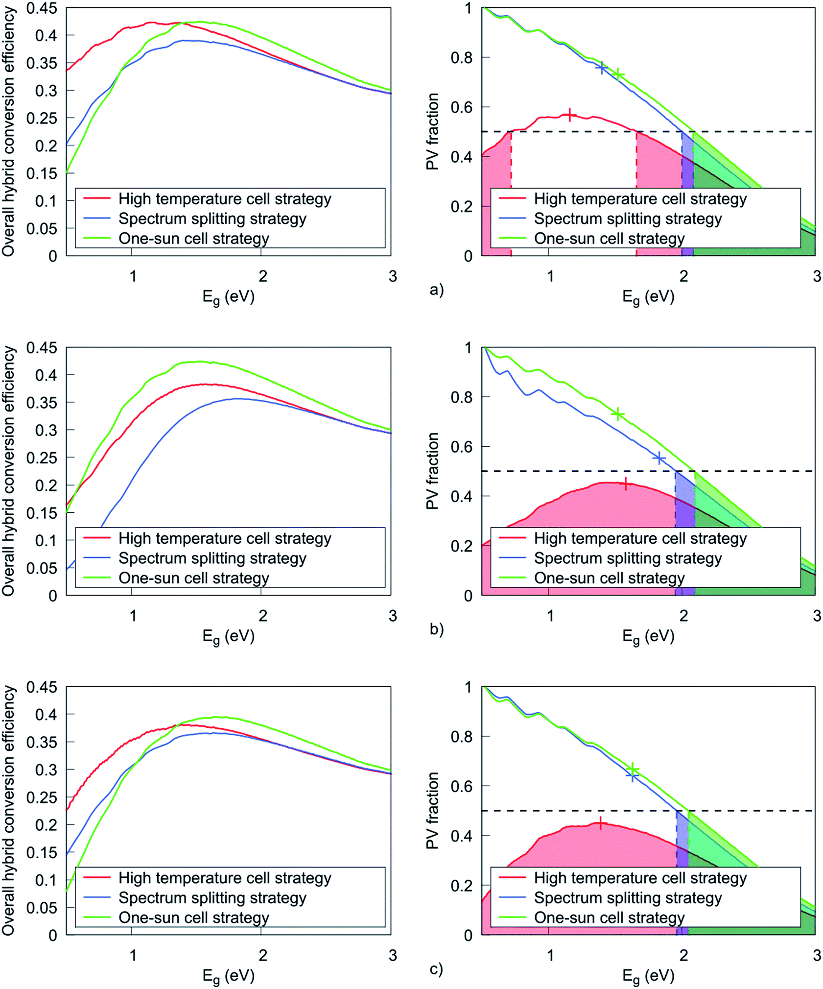 | ||
| Fig. 2 Overall conversion efficiency of hybrid PV/CSP systems (left), and the PV fraction (right), as a function of Eg, assuming PVs (a) operate at the radiative limit, (b) with Rs = 0.01 Ω cm2, and (c) with ηlum = 1%. In all cases, the thermal receiver delivers hot fluid to the turbine at 393 °C, the ambient temperature is 25 °C, and C = 1000. All efficiencies are relative to global solar radiation, with the global-to-direct ratio taken as 1.3 as explained in the text. The conversion efficiency of the CSP sub-system alone is 0.28. The crosses in the right-hand-size plots indicate the points at which the overall hybrid system efficiency peaks for each strategy, and the dashed horizontal line is included simply to guide the eye in discerning when the PV fraction is 0.5. Concomitantly, the shaded regions highlight when the PV fraction is below 0.5. | ||
In Fig. 2, the right-hand graphs show the PV fraction as a function of Eg. Peak overall system efficiency is indicated by crosses. The shaded areas indicate a PV fraction ≤ 0.5.
The 3 hybrid strategies demonstrate similar trends for the dependence of system efficiency on Eg, with peak efficiencies occurring in the range Eg ≈ 1.1–1.5 eV (Fig. 2a). As noted above, for consistent comparisons among all 3 strategies, these evaluations relate to single-junction cells. Hence the energetically optimal Eg values are close to those computed for harvesting the full solar spectrum at 1 sun and ambient temperature.30 Variations of a few tenths of an eV from the standard optimal Eg stem from its dependence on both C and substantially higher temperature.
Fig. 2b and c illustrate the behavior of all 3 approaches, but taking a step closer to realistic cells by including, respectively, non-negligible series resistances losses (Rs = 0.01 Ω cm2), and strong non-radiative recombination (an external luminescence efficiency of ηlum = 1%). The “1 sun cell” approach is more tolerant to series-resistance losses (a consequence of a lower photo-generated current density). Namely, Rs was chosen as an attainably low value for concentrator cells, such that the associated efficiency penalty at the high current densities generated at C ≈ 1000 is only ∼10% relative. For a cell operating at 1 sun, with current densities that are ∼3 orders of magnitude lower, the corresponding efficiency penalty is negligible, which explains why, in Table 3, there is no apparent efficiency reduction for the 1 sun cell approach when Rs is introduced.
| PV cell model | High temperature cell | Spectrum splitting | 1 sun cell |
|---|---|---|---|
| Radiative limit | η = 42.3% | η = 39.0% | η = 42.4% |
| PVf = 56.7% | PVf = 75.7% | PVf = 73.1% | |
| R s = 0.01 Ω cm2 | η = 38.3% (−10%) | η = 35.7% (−9%) | η = 42.4% (0%) |
| PVf = 44.9% | PVf = 55.3% | PVf = 73.1% | |
| η lum = 1% | η = 38.1% (−10%) | η = 36.7% (−6%) | η = 39.5% (−7%) |
| PVf = 45% | PVf = 64.2% | PVf = 66.9% |
Both the “high-temperature cell” and the “spectrum-splitting” approach show a significant shift in the Eg value at which system efficiency peaks (Eg = 1.16–1.58 eV for the former, and 1.40–1.83 eV for the latter), as well as a drop in the maximum attainable efficiency (Fig. 2b).
Fig. 2c shows that despite the non-negligible effects of non-radiative recombination in the case of low-Eg materials, the maximum attainable efficiency with each one of the 3 approaches shows only a modest decline relative to the ideal case, because of the relatively high Eg values at which the hybrid efficiency peaks.19 The “1 sun cell” approach also yields the highest conversion efficiency even in the presence of non-radiative recombination. Despite the favorable effect of concentration on the cell's sensitivity to non-radiative recombination, both approaches involving concentrated sunlight on the PVs show lower conversion efficiency than the 1 sun approach due to (1) the inherent inability to concentrate diffuse sunlight, (2) the detrimental effect of elevated operating temperature, and (3) the lower conversion efficiency of the “spectrum-splitting” approach as a consequence of not exploiting cell thermalization. The maximum efficiency with each approach is summarized in Table 3, both for PVs in the radiative limit, as well as for cells with series-resistance and non-radiative losses, and including the individual contributions of the PV fraction.
In general, high-temperature operation of PV cells may lead to a significant increase in both series resistance (mainly because of decreased carrier mobility31) and non-radiative recombination. The efficiency penalty associated with these two loss mechanisms may significantly exceed the values reported here. However, since (1) the aim here is a comparison among strategies (rather than a precise determination of system performance), and (2) values of both Rs and ηlum at high cell temperature have not been reported, we chose to restrict this study to state-of-the-art single-junction concentrator solar cells for which Rs and ηlum values are the same as those near ambient temperature.
There are optical and geometric losses stemming from the particular concentrator used, i.e., beyond the optical losses inherent to PVs and thermal absorbers – typically in the range of 10–30%. Because they do not markedly influence the intrinsic performance of the PV or thermal converter, they were not included in our results. But there are two other reasons for imposing this separation.
First, the optical and geometric losses are location-specific and case-specific, as well as depending on the optical quality of the mirrors and/or lenses.
Second, the averaged cosine of the incidence angle 〈cos(θ)〉 can differ non-negligibly with concentrator type and site latitude. For example, for both 2D and 3D Fresnel reflectors, 〈cos(θ)〉 is non-negligibly <1, because the normal to the surface of each mirror segment bisects the angle between the sun and the receiver. This stands in contrast to dual-axis tracking paraboloidal dishes and point-focus Fresnel lenses, where 〈cos(θ)〉 is 1. Also, as a consequence of the varying solar elevation angle, line-focus systems exhibit solar beam spreading in the plane orthogonal to that in which beam concentration is determined.
So the efficiency figures presented herein need to be adjusted by the non-intrinsic concentrator-related and location-related losses described above. We stress that the primary aim here is establishing performance bounds and a comparative perspective for hybrid solar power strategies. Detailed location-dependent and concentrator-dependent results are deferred to future targeted investigations.
Additional spectrum-splitting degree of freedom
The two spectrum-splitting strategies can be broadened to include the additional degree of freedom of redirecting photons with energy exceeding a cutoff Ecutoff > Eg to the thermal absorber. The energetically optimal Ecutoff values were computed, using an optimization algorithm allowing the determination of the electronic gaps for which the overall efficiency peaks. As in the preceding sub-section, attention was constrained to the scenario of C = 1000 and TCSP = 393 °C.However, the results showed only near-negligible improvements in the maximum hybrid efficiency and the PV–thermal balance, and hence were not elaborated further.
Conclusions
Can hybrid PV–CSP strategies dramatically improve system conversion efficiency relative to the conventional existing alternative of completely separate corresponding PV and CSP systems? Prior reports1 had anticipated an affirmative answer, but the results derived above indicate otherwise. The largest improvement appears to be 10% relative, for the high-temperature cell approach (with an integrated PV–thermal absorber). Every additional percentage point of energetic efficiency in power plants is deemed significant. Nonetheless, the planning and design of hybrid solar power plants have not, to our knowledge, been moderated by a clear evaluation and recognition of the modest magnitude of the maximum possible improvement relative to the simple option of completely separate CSP and PV plants.The energetic superiority of the high-temperature cell approach is rooted in fundamental thermodynamics. To wit, in all other strategies, the sizable thermalization losses incurred by PV cells are rejected to the environment and hence unutilized. The integrated PV–thermal receiver, however, reclaims the heat for high-temperature conversion in conventional steam turbines.
Two caveats are in order. First, our results relate to upper bounds on the respective performance of both the PV and thermal systems, albeit mediated by also considering PVs with more realistic losses from series resistance and non-radiative recombination. And second, our results pertain only to the losses inherent to the physics of energy conversion in the PVs and the thermal (collector/turbine) system. Namely, the optical and geometric losses associated with the particular concentrator employed, field layout, and location (latitude and global/direct ratio for solar radiation) are not included in our comparisons, precisely because they are not intrinsic to the energy conversion mechanisms under consideration, and hence could equally well be applied to each of the hybrid strategies.
Short of the type of calculations presented here, there is no quick or analytic way to predict either the efficiency bounds or the respective PV fractions. The results derived here are meaningful for systems intended to achieve both maximum efficiency and a sizable thermal power delivery (the latter for providing adequate dispatchability – a judgment that is case-specific, but arguably not deviating markedly from a 50–50 division). The fact that only the high-temperature integrated-receiver approach can offer close to a 50–50 mix augurs in its favor.
For the hybrid strategy that offers the highest potential efficiency – the high-temperature-cell approach – a thermal operating temperature of 393 °C turns out to be near-optimal energetically. At first glance, this finding may seem unusual given that turbine efficiency increases with temperature, conflated with the ability of point-focus solar concentrators to deliver even higher temperatures. However, the physics of the problem indicates that the loss of PV efficiency as temperature increases compensates. This compensation is more pronounced at lower solar concentration, where absorber heat loss is non-negligible. It is a remarkable coincidence that the temperature for the efficiency optimum just happens to fall where today's line-focus CSP systems operate.
Several additional qualifications are in order regarding restrictions on the scope of the analysis. For self-consistency in comparisons among all the hybrid strategies, attention was limited to single-junction PVs. The degree to which cell efficiency can be enhanced via the introduction of multiple junctions at high concentration has been well documented, but only for operation close to ambient temperature.30 To our knowledge, there are no studies of this nature at the temperatures required for the high-temperature-cell approach. Future investigations are planned to expand the analysis to multi-junction cells that can remain acceptably efficient even at elevated temperatures. There is also the unresolved question of whether PV cells can exhibit long-term stability at higher temperatures (with preliminary encouraging results4–6).
Finally, we find that even if the two spectrum-splitting strategies admit the extra degree of freedom of redirecting the high-energy end of the solar spectrum to the thermal receiver, they are still unable to mitigate substantial thermalization losses, and thus cannot provide a perceptible efficiency boost relative to the simpler single-cutoff spectral filter.
Conflicts of interest
There are no conflicts to declare.Acknowledgements
This work was supported in part by the Program “Investment for the Future” of the National Agency for Research of the French State under award number ANR-10-LABX-22-01-SOLSTICE.References
- ARPA-e FOCUS Program overview, http://arpa-e.energy.gov, accessed September 2017.
- H. M. Branz, W. Regan, K. J. Gerst, J. B. Borak and E. A. Santori, Energy Environ. Sci., 2015, 8, 3083–3091 RSC.
- E. E. Perl, J. Simon, J. F. Geisz, M. L. Lee, D. J. Friedman and M. A. Steiner, IEEE Journal of Photovoltaics, 2016, 6, 1345–1352 Search PubMed.
- Y. Sun, J. Faucher, D. Jung, M. Vaisman, C. McPheeters, P. Sharps, E. Perl, J. Simon, M. Steiner, D. Friedman and M. L. Lee, Proc. 43rd IEEE Photovoltaic Specialists Conf., Portland, OR, 2016, pp. 2385–2388 Search PubMed.
- E. E. Perl, J. Simon, D. J. Friedman, N. Jain, P. Sharps, C. McPheeters, Y. Sun, M. L. Lee and M. A. Steiner, IEEE Journal of Photovoltaics, 2018, 8, 640–645 Search PubMed.
- J. J. Williams, H. McFavilen, A. M. Fischer, D. Ding, S. Young, E. Vadiee, F. A. Ponce, C. Arena, C. B. Honsberg and S. M. Goodnick, IEEE Journal of Photovoltaics, 2017, 7, 1646–1652 Search PubMed.
- A. Mojiri, C. Stanley, D. Rodriguez-Sanchez, V. Everett, A. Blakers and G. Rosengarten, Appl. Energy, 2016, 169, 63–71 CrossRef.
- C. Stanley, A. Mojiri, M. Rahat, A. Blakers and G. Rosengarten, Appl. Energy, 2016, 168, 303–313 CrossRef.
- B. Widyolar, L. Jiang and R. Winston, Appl. Energy, 2018, 209, 236–250 CrossRef.
- M. Abdelhamid, B. K. Widyolar, L. Jiang, R. Winston, E. Yablonovitch, G. Scranton, D. Cygan, H. Abbasi and A. Kozlov, Appl. Energy, 2016, 182, 68–79 CrossRef.
- B. K. Widyolar, M. Abdelhamid, L. Jiang, R. Winston, E. Yablonovitch, G. Scranton, D. Cygan, H. Abbasi and A. Kozlov, Renewable Energy, 2017, 101, 1379–1389 CrossRef.
- L. A. Weinstein, K. McEnaney, E. Strobach, S. Yang, B. Bhatia, L. Zhao, Y. Huang, J. Loomis, F. Cao, S. V. Boriskina, Z. Ren, E. N. Wang and G. Chen, Joule, 2018, 2, 962–975 CrossRef.
- D. M. Bierman, A. Lenert and E. N. Wang, Appl. Phys. Lett., 2016, 109, 243904 CrossRef.
- T. P. Otanicar, S. Theisen, T. Norman, H. Tyagi and R. A. Taylor, Appl. Energy, 2015, 140, 224–233 CrossRef.
- Y. Vorobiev, J. González-Hernández and A. Kribus, J. Sol. Energy Eng., 2006, 128, 258–260 CrossRef.
- Y. Vorobiev, J. González-Hernández, P. Vorobiev and L. Bulat, Sol. Energy, 2006, 80, 170–176 CrossRef.
- R. Winston, J. C. Miñano, P. Benítez, N. Shatz and J. Bortz, Nonimaging Optics, Academic Press, Amsterdam, 2005 Search PubMed.
- W. Shockley and H. J. Queisser, J. Appl. Phys., 1961, 32, 510–519 CrossRef.
- A. Vossier, F. Gualdi, A. Dollet, R. Ares and V. Aimez, J. Appl. Phys., 2015, 117, 015102 CrossRef.
- A. S. Brown and M. A. Green, Phys. E, 2002, 14, 96–100 CrossRef.
- C. K. Ho and B. D. Iverson, Renewable Sustainable Energy Rev., 2014, 29, 835–846 CrossRef.
- X. Han, C. Xu, X. Ju, X. Du and Y. Yang, Sci. Bull., 2015, 60, 460–469 CrossRef.
- X. Han, G. Zhao, C. Xu, X. Ju, X. Du and Y. Yang, Appl. Energy, 2017, 189, 520–533 CrossRef.
- HCEMS-11 and HCEMS-12 receiver tubes, Archimede Power Plant – ENEL, Archimede Solar Energy SRL, Massa Martana PG, Italy, 2015.
- E. Batuecas, C. Mayo, R. Díaz and F. J. Pérez, Sol. Energy Mater. Sol. Cells, 2017, 171, 91–97 CrossRef.
- L. Moens and D. M. Blake, J. Sol. Energy Eng., 2010, 132, 031006 CrossRef.
- H. Benoit, L. Spreafico, D. Gauthier and G. Flamant, Renewable Sustainable Energy Rev., 2016, 55, 298–315 CrossRef.
- J. M. Gordon and M. Huleihil, J. Appl. Phys., 1992, 72, 829–837 CrossRef.
- National Radiation Data Base (NREL), http://rredc.nrel.gov/solar/old_data/nsrdb/, accessed September 2017.
- C. H. Henry, J. Appl. Phys., 1980, 51, 4494–4500 CrossRef.
- S. M. Sze and K. K. Ng, Physics of Semiconductor Devices, Wiley, Hoboken, 2007 Search PubMed.
Footnote |
| † Electronic supplementary information (ESI) available. See DOI: 10.1039/c8se00046h |
| This journal is © The Royal Society of Chemistry 2018 |