Hydrogen derived from water as a sustainable solar fuel: learning from biology
James
Barber
Department of Life Sciences, Imperial College London, Sir Ernst Chain Building, South Kensington Campus, SW7 2AZ, UK. E-mail: j.barber@imperial.ac.uk; Tel: +44 (0)208 747 1165
First published on 23rd March 2018
Abstract
The United Nations Climate Change Conference (COP21) held in Paris in 2015 and the follow-up conferences in Marrakesh (COP22) and very recently in Bonn (COP23) have established an unprecedented international agreement that during this century human society must break from its reliance on energy from fossil fuels to energy sources, which do not release greenhouse gases, particularly carbon dioxide. This is a very hard call. It will not only involve improving more efficient use of energy but also the establishment of new technologies and infrastructures for its generation and distribution. Among renewable energy resources able to tackle these challenges significantly are nuclear or those derived from solar radiation. However in the case of nuclear fusion, a technological breakthrough is required while nuclear fission is limited in the long run by the finite supply of uranium fuel. Here I focus on solar energy which is already contributing to the challenge of COP21. In particular, I discuss its capture and storage through the splitting of water to produce oxygen and hydrogen reducing equivalents, which is essentially the route taken by biology about 3 billion years ago. In so doing I will describe how Nature goes about achieving this fundamental energy converting reaction as a back drop to efforts to achieve the same goal using non-biological photo-electrochemical technology.
Introduction
It is well recognised that solar energy captured directly by photovoltaic (PV) cells or indirectly as hydro-, wind- and wave-power, could and should be the major renewable energy source for the future. After all it is often stated that one hour of sunlight falling on our planet would power global human life and activities for a year. Slowly we see this goal being recognised with substantial increases in the production and installation of PV panels, wind turbines, hydroelectric systems and the development of wave power technology. In total these solar driven technologies provide about 10% of the current global energy demand (see Fig. 1).1,2 In all cases the end product is electricity. Biomass and biofuels are also products of solar energy and contribute less than 1% of our global energy requirement as shown in Fig. 1. However this percentage increases if the burning of wood and other organic materials for cooking and heating, in undeveloped countries, is taken into account. At the moment, as these countries move out of poverty they too are turning to the use of fossil fuels. The use of biofuels is being encouraged in developed countries but this approach competes with food production and can lead to undesirable ecological consequences as the result of, for example, deforestation and loss of habitat for vulnerable plant and animal species. Nevertheless some countries are blessed with a large land mass and ideal growing conditions for ecologically managed, sustainable, biomass/biofuel production.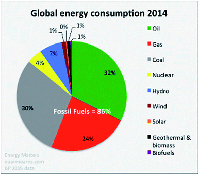 | ||
| Fig. 1 Global energy consumption estimated in 2014. During the past three years the relative proportions have not changed significantly with fossil fuels dominating at more than 85% (taken from BP Statistical Review 2015),1http://euanmearns.com/global-energy-trends-bp-statistical-review-2015. | ||
Electricity is an excellent energy carrier but its storage in large amounts is also vital. There are two ways to tackle this challenge; electrochemically in batteries or in chemical bonds of molecules such as hydrogen. In the case of the latter, the density of energy stored is much higher than that achieved by solid state batteries although this difference may narrow if battery technology continues to improve such as a new generation of flow batteries.
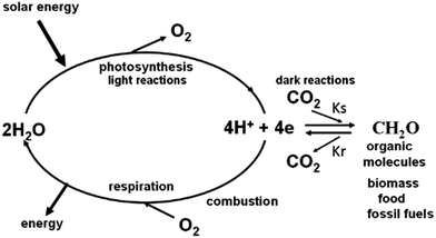
The storage of solar energy in chemical bonds is the basis of the energy cycle of our planet.3,4 Through the process of photosynthesis, light energy is stored in organic molecules that constitute the global biomass and is the origin of our fossil fuels.5 Biomass provides energy for animal life via respiration while the combustion of fossil fuels powers the majority of our extensive technologies to the benefit of an ever increasing and demanding world population (see Fig. 2 and its legend).
Over a period of a year the rate of energy storage for the whole of global photosynthesis is about 10 terawatts (TW). This is achieved by an overall low global efficiency of 0.01% due to the fact that much of the Earth's surface is not, or poorly, active in photosynthesis (deserts, polar regions and deep oceans) as well as seasonal changes (winter senescence). On the other hand the efficiency can be as high as 2% when plants are grown under optimal conditions, such as sugar cane in the plantations of Brazil.4,5 The average long term global energy storage is mainly achieved by terrestrial plants where the storage can be in the form of wood and other types of biomass. The photosynthetic activity of the oceans is about the same as for land plants but the storage time of energy is much less because of the rapid turnover rate of phytoplankton and algae.6 The 10 TW available from global photosynthesis compares with the current yearly average power demand of about 17 TW by the world's population of 7.5 billion.7 Therefore of the 32 Gt of CO2 released into the atmosphere per year at the present time, only about a half of it is recycled through the biosphere. As a consequence there is a steady rise in atmospheric CO2 levels (370 ppm in 2000 to 408 ppm in 2017). As the global population increases, the annual average power consumption could reach 30 TW by 2050, representing three times that coming from all the oxygenic photosynthetic activity of our planet. Clearly the challenge is to develop carbon free technologies which can dramatically slow down, or prevent, the continuing release of CO2 resulting from burning fossil fuels. In the case of solar driven technology a year-round average efficiency significantly higher than that of current plants or algae is required to reduce land-area requirements and so be independent of food production.
Against this backdrop of developing highly efficient solar energy technologies operating on a very large scale, is the realization that fossil fuels are relatively cheap and abundant. This is because fossil fuels were derived from oxygenic photosynthesis which appeared on our planet about 3 billion years ago. The overall equation of photosynthesis below (eqn (1)) shows that for every molecule of O2 produced from the splitting of two water molecules, one molecule of CO2 is converted into organic molecules such as carbohydrate (CH2O).
 | (1) |
Since today there is 21% O2 in the atmosphere and as far as we know is derived entirely from photosynthesis, then the amount of reduced carbon on our planet is enormous. This means that there is essentially an almost unlimited supply of fossil fuels although presumably a great deal of the reduced carbon will not be readily obtainable. If it were, and if it was all burnt, then our planet would return to its original anaerobic state with a very high level of CO2 in the atmosphere.
As indicated in Fig. 2 including its legend, the heart of the photosynthetic process is the light driven splitting of water providing hydrogen equivalents as a reducing agent to power the synthesis of organic molecules with the formation of molecular oxygen as a by-product.8,9 Thus if solar energy is to be captured and stored as a fuel on a large scale, then the challenge will to be to mimic biology and obtain hydrogen from water. A water molecule is chemically very stable and splitting it into its constituents is thermodynamically and chemically demanding. Amazingly, this is achieved efficiently by oxygenic photosynthetic organisms in a delicate protein environment of an enzyme and powered by the relatively low energy content of four photons of long wavelength visible light (eqn (2)).10
The importance of this fundamental chemical reaction, which is the entry point for the energy cycle of our planet, cannot be over stated. Indeed, it was the evolution of the water splitting reaction of photosynthesis by which biology solved its energy problem. Therefore it is important to explore how this reaction is achieved so that humankind can more confidently develop technologies to address the energy/climate change issues which must be solved within this century.
Water splitting in natural photosynthesis
This fundamental photosynthetic reaction occurs at a catalytic site within a membrane located enzyme known as Photosystem II (PSII).4,8 This enzyme is made up of many different protein subunits with some binding chlorophyll and other pigments which capture photons and deliver excitation energy to a reaction centre where charge separation occurs. Four charge transfer states sequentially use their energy for oxidising two molecules of water to molecular oxygen and for the reduction of two plastoquinone (PQ) molecules, which act as the terminal electron acceptor of PSII (eqn (2)). | (2) |
PQH2 passes its “hydrogen”, in the form of reducing equivalents, to an electron/proton transfer chain which feeds into Photosystem I (PSI) where additional reducing potential is generated by a second light reaction to a level necessary to convert CO2 into organic molecules such as carbohydrates (CH2O) as depicted in eqn (1).4
As shown by eqn (2) and in Fig. 3, the water splitting reaction of PSII requires four quanta of light and involves at least five intermediate states (S0 to S4), whereby four oxidising equivalents of about the same potential are sequentially accumulated at the catalytic site with the absorption of each photon of visible light. The S4-state stores the four oxidising equivalents needed to oxidise two water molecules to produce molecular oxygen (eqn (2)) and in so doing reverts back to the S0-state. The oxidising equivalents are accumulated by four Mn ions in the catalytic centre leading to four MnIV ions in the S3-state just before the last photochemical step to S4.11 The precise details of this final oxidation state are unknown because O–O bond formation is very fast so as to avoid detrimental side reactions. The cycle is powered by the oxidation of the reaction centre chlorophyll known as P680 generated by light driven primary charge separation in the reaction centre of PSII coupled to a redox active tyrosine (YZ), serving as an intermediate electron carrier between P680+ and the Mn-cluster.12,13
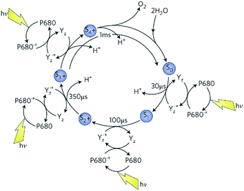 | ||
| Fig. 3 The S-state cycle showing how the absorption of four photons of light (hv) by the reaction centre primary oxidant P680 drives the splitting of two water molecules and formation of O2 through a consecutive series of five intermediates (S0, S1, S2, S3 and S4). Protons (H+) are released during each step of this cycle except for the S1 to S2 transition. Electron donation from the Mn4Ca2+ cluster to P680˙+ is aided by the redox-active tyrosine YZ. Each step involves a single oxidation of a Mn ion in the cluster, starting at S0 with 3 × MnIII plus MnIV advancing to S3 with 4 × MnIV. The exact oxidation state of S4 is unknown but could be 3 × MnIV plus MnV or 3 × MnIV plus MnIV-oxyl radical (see below). Also shown are half-times for the various steps of the cycle. Taken from Barber.9 | ||
With my colleagues at Imperial College London, we concluded from X-ray diffraction analysis of PSII crystals at 3.5 Å resolution, that the oxygen generating catalytic centre of PSII consisted of a Mn3Ca2+O4 cubane with a fourth “dangler” Mn (Mn4) attached to the cubane via one of its bridging oxo bonds.14 Further refinement of this Mn4Ca2+O4 structure at 1.9 Å by Umena et al.15 seven years later, confirmed this geometry but added one additional bridging oxo bond between the external dangler Mn4 and the cubane to make a Mn4Ca2+O5 cluster. They also confirmed our identification of the amino acids associated with the cluster and refined the details of their ligation (see Fig. 4). More recently a Mn4Ca2+O4 cluster has been synthesised in the absence of protein and its structure is essentially identical to that proposed from my laboratory eleven years earlier.16
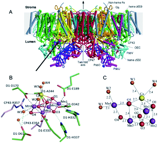 | ||
| Fig. 4 (A) A side view of the structure of the dimeric PSII complex described in detail in Ferreira et al.14 (B) and (C) structure of the Mn4Ca2+O5-cluster of the water splitting catalytic site of PSII described in detail in Umena et al.15 | ||
Over the years there have been many postulates of a mechanism of water splitting by PSII.17–26 Here I emphasise a chemical mechanism, the essence of which has been championed by several groups27–37 and which I have favoured for many years29 since it seems to be consistent with the geometrical features of the catalytic centre of PSII. As shown in Fig. 5, the postulate is that molecular oxygen formation involves a substrate water, associated with Mn4 which is outside the cubane. This water molecule is deprotonated during the S-state cycle and forms a highly electrophilic oxo. It also requires Mn4 being converted to a high oxidation state (possibly MnV or a reactive MnIV-oxyl radical) during progression to the S4-state just prior to O–O bond formation. The other three Mn ions are also in high valence state (3 × MnIV) at this stage and act as a further “oxidising battery” for the MnV-oxo or MnIV-oxyl radical species on Mn4. In this way the reactive oxo linked to Mn4 is electron deficient, so much so that it makes an ideal target for a nucleophilic attack by the oxygen of the second partially deprotonated substrate water bound within the coordination sphere of the Ca2+. The deprotonation of the substrate waters would be aided by nearby basic amino acids while the weak Lewis acidity of Ca2+ allows the coordination of the substrate water or hydroxyl to be ideally positioned for the nucleophilic attack. There is an extensive H-bonding network leading from the catalytic centre to the outside of the PSII complex. A very important aspect of this mechanism is that proton coupled electron transfer (PCET) occurs to avoid the build-up of a significant coulombic charge during the cycle, although one positive charge is accumulated during the S1 to S2 transition which adds to the overall oxidising potential of the Mn3Ca2+ cubane in the higher S-states. An interesting comparison between PSII and carbon monoxide dehydrogenase which both extract hydrogen reducing equivalents from water and have very similar geometries of their catalytic centres, also supports the nucleophilic mechanism on the surface of their Mn3Ca2+O5 and Fe3Ni2+S5 cubanes respectively.36
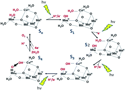 | ||
| Fig. 5 Diagrammatic representation of a mechanistic scheme for water splitting and dioxygen formation in PSII. The substrate water molecules and products of the oxidation reactions for each S-state are shown in red. Intermediates that may exist between the S-state transitions are not depicted nor is the possible peroxide intermediate just prior to O–O bond formation. Although the electrophilic oxo in the S4 state is shown attached to MnV it could equally be incorporated in a terminal MnIV-oxyl. Taken from Barber.36 The essence is that a proton (H+) and an electron (e−) are removed by PECT for the flash induced S0 to S1, S2 to S3, and S3 to S4 light driven transitions but only an electron is removed during the S1 to S2 transition resulting in the accumulation of a positive charge in the metal cluster as shown. The final S3 to S4 flash induced transition progresses to a highly electrophilic terminal oxo (electron deficient) ideally poised for an nucleophilic attack by a hydroxyl coordinated to the nearby Ca ion (electron rich). Although the electrophilic oxo in the S4 state is shown attached to MnV it could equally be an energy equivalent terminal MnIV-oxyl radical. | ||
To absolutely prove this mechanism experimentally, or any other alternative mechanisms, will be a challenge. This is because the solvent for this enzyme is water and the reactants are H2O, OH and O which will require the application of techniques to detect changes at the level of individual protons. Nevertheless some very impressive X-ray Free Electron Laser (XFEL) diffraction studies on PSII have recently been reported38–40 but with resolutions far from that required to detect protons and therefore identify a specific mechanism. This approach, however, should reveal any large conformational changes in the catalytic site as advocated by some other proposed mechanisms.21
Studies with synthetic model complexes play an important role in the challenge of understanding the mechanism of water splitting by PSII. The hydroxyl/water nucleophilic attack concept for O–O bond formation has been proposed in Mn complexes with the involvement of MnV.41–43 Moreover, it seems that the nucleophilic attack mechanism can be a dominant reaction for water splitting and oxygen formation by mononuclear Ru complexes oxidised by CeIV where the electrophile is RuV![[double bond, length as m-dash]](https://www.rsc.org/images/entities/char_e001.gif) O and nucleophile is solvent water.44,45
O and nucleophile is solvent water.44,45
Water splitting in artificial photosynthesis
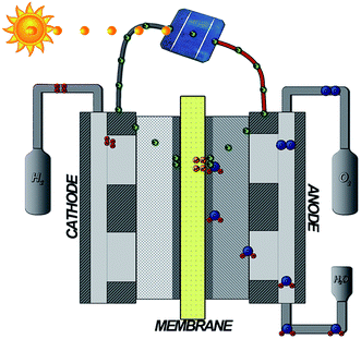
The organometallic constructs mentioned above, as well as the isolated PSII complex, are providing an understanding of the mechanism of water splitting and O–O bond formation, and importantly how to achieve high turnover rates. Such systems have been incorporated into functional devices. For example, Li et al.71 produced a dye-sensitized water splitting cell with an organic dye to activate a Ru based catalyst for O2 production at the anode, combined with a cathode based on a dye-activated cobaloxime catalyst to generate H2 at neutral pH with no applied electrical bias. Here the overall solar-to-chemical efficiency is low over the entire solar spectrum but quantum yield of 25% could be measured when exposed to 380 nm light. However they are unlikely to be incorporated into an artificial photosynthesis technology because of their fragility. What is needed are robust, non-toxic and cheap catalysts for splitting water over long periods of time (years). They will also be required to use solar energy to power the reaction.46–48 The simplest design would be to use a semiconductor to absorb visible light and generate charge separation rather like the reaction centre in PSII. Ideally the excited electrons in the conduction band should be sufficiently energetic to drive proton reduction to hydrogen while the holes left in the valence band have a large enough potential to oxidise water. In some cases the water splitting process may occur at semiconductor surfaces but since the reactions are multi-electron, a bound co-catalyst may be required to achieve maximum rates. For this purpose, a wide range of metal oxides have been explored49 with Co being particularly effective,50–53 while mixed metal oxides of iron and nickel are also promising.54 These co-catalysts have been employed with several semiconducting light harvesting systems including triple junction amorphous Si,55 heterojunction n-type crystalline Si(100) substrates coated with a thin ∼50 nm film of cobalt oxide fabricated using atomic-layer deposition56 and haematite (Fe2O3).57,58 Haematite is an attractive candidate because it is cheap, non-toxic and a good absorber of the solar spectrum. Its band gap is 2.1 eV vs. RHE and the light generated holes have sufficient oxidising power (+2.0 eV vs. RHE) to split water Haematite nanorods, in combination with doping and surface passivation with Mn or Sn, are proving to help maximise these advantages.59 Aematite requires nano-structuring to enhance light absorption, minimise charge carrier distances and reduce the extent of recombination reactions57,58 as also found with Si-based wires.56 One artificial leaf device using Co-doped haematite nanorods is shown in Fig. 6. Here, Co–phosphate is used as the co-catalyst. | ||
| Fig. 6 Diagrammatic representation of a tandem photoelectrochemical cell incorporating a hybrid organic–inorganic lead halide perovskite (CH3NH3PbI3) and haematite (Fe2O3) nanorods doped with Co and requiring no external electrical bias for photo-driven water splitting. Taken from Gurudayal et al.60 | ||
Haematite conduction band potential is not reducing enough to produce hydrogen without the application of some electrical bias. As explained above, the reducing equivalents generated by PSII also cannot drive hydrogen production directly and the bias is satisfied by light energy absorbed by PSI making the formation of O2 an eight light quanta reaction as indicated in eqn (1).4 Here, the extra bias for hydrogen production is generated by the photovoltaic activity of a hybrid organic–inorganic lead halide perovskite tightly coupled to the photoanode. The next step will be to incorporate a non-platinum catalyst into this “artificial leaf” device, which will use the protons and high energy electrons derived from the water splitting reaction to produce hydrogen gas. Indeed considerable progress is being made by mimicking the natural hydrogenase enzymes found in a wide variety of microorganisms.61,62 Also a number of metals and inorganic catalysts have been identified with activities which are almost as good as platinum as shown in the volcano plots.48,63 A very good class of catalysts are based on sulphides and phosphides of Mo and W which can match the effectiveness of pure metal cathodes (Fig. 7).48,63–67
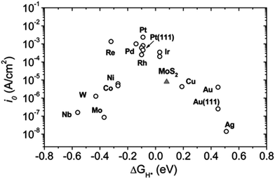 | ||
| Fig. 7 Volcano plot of the exchange current density as a function of the density function theory-calculated Gibbs free energy of adsorbed atomic hydrogen for nano-particulate MoS2 and some active metals. As seen, MoS2 follows the same trend as metals. The MoS2 exchange current density is normalized to the atomic site density of Pt for comparison. Samples are polycrystalline unless otherwise noted. Taken from Jaramillo et al.63 Also see Seh et al.48 | ||
One successful example of coupling of catalysts with a semiconductor for light capture and charge separation was reported by Nocera and colleagues.55 They used a triple junction amorphous Si wafer as the semiconductor, a CoPi catalyst for water splitting and a NiMoZn alloy for the cathodic hydrogen producing catalyst as shown in Fig. 8. This example represents a significant step towards the development of an efficient, robust, low-cost and scalable photocatalytic device for water splitting at neutral pH to generate molecular hydrogen using solar energy only. In that perspective, noble-metal-free coating that can function as a robust, bifunctional and switchable catalysts for H2 or O2 evolution may be desirable to avoid ion-crossover between anode and cathode compartment and limit deactivation upon cell reversal processes. Cobo et al.68 found that a metallic cobalt coated with a cobalt-oxo/hydroxo-phosphate layer in contact with the electrolyte mediates H2 evolution from neutral aqueous buffer at modest overpotentials. Remarkably, it can be converted on anodic equilibration to the Nocera CoPi, O2 evolution catalyst. The switch between the two catalytic forms is fully reversible and corresponds to a local interconversion between two morphologies and compositions at the surface of the electrode.
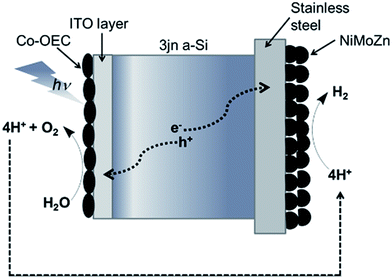 | ||
| Fig. 8 Diagrammatic representation of Nocera's photocatalytic “artificial leaf” device for water splitting consisting of a triple n-junction amorphous silicon wafer, Co-based oxygen evolving catalyst and NiMoZn H2-evolving catalyst as reported in Reece et al.55 | ||
These and other examples of hydrogen producing photoelectrochemical cells (PEC) are only explored at the laboratory level despite a worldwide explosion of research in this area. But there are some interesting recent developments using particulate semiconductors for both oxygen production and hydrogen generation which are electrically linked to produce a two photon per electron tandem system.69 These powder based systems lend themselves to making functional sheets up to one meter square and can generate hydrogen when illuminated with natural sunlight but at a low efficiency of 0.4%.70 A record efficiency of 30% for solar water splitting has been reported by Jia et al.72 when they coupled two electrolyte polymer membrane electrolysers in series with a InGaP/GaAs/GaInAsSb triple-junction solar cell. Although this is an impressive demonstration of proof of concept, it is inconceivable that GaAs-based semiconductors could be used on a massive scale due to the cost and relatively low abundance of gallium.
Given that at present, the annual average global power consumption is about 17 TW, with the expectation of a considerable increase by 2050, “artificial leaf” technology is unlikely to have significant impact on present and near future energy supplies. However, it is always difficult to predict the emergence of new technology and the present focus of attention on this area of solar energy capture and storage is vital and must continue to grow with urgency. In this respect there are a number of efforts ongoing. For example there is the Joint Centre for Artificial Photosynthesis73 and associated programmes funded by the US Department of Energy74 and the EU funded project Artiphyction, a-leaf and PECDEMO.75 However there must be more effort directed at developing scalable technology which can compete in financial terms with the relatively low cost and abundance of fossil fuels. For large scale energy production the employment of PV to capture solar energy efficiently seems more realistic and then to use the photo-current at dedicated sites to drive water splitting using a new generation of efficient low cost electrochemical cells (Fig. 9). Currently, electrolysis of water to obtain “green” hydrogen on a large scale is expensive. However, as mentioned above, low cost and non-toxic materials are being identified as alternatives to platinum for the electrochemical splitting of water. The establishment of a new generation of electrolysers resulting from this research can also be used to store electricity derived from other sources such as wind-, hydro-, wave- and nuclear-power. But they must have very good turnover rates to cope with high levels of electricity supplies. The more tightly coupled solar driven systems, like that shown in Fig. 6 and 7, may have application at the personal level however, such as individual houses and as a fuel source in remote areas in under-developed countries.
Overall opinion
Hydrogen, generated by the electrolysis of water, is an excellent clean energy carrier with a high energy density in its compressed form76 compared with solid state batteries. Thus it is ideal for transport systems including automobiles, buses, motor cycles, ships and aircraft which have been reinforced by demonstration prototypes. Compressed H2 can be used directly in an internal combustion engine or more efficiently to produce electricity via fuel cells. Hydrogen based fuel cell electrical vehicles (FCEV) are now being built commercially, like the Toyota Miria and very recently the 2017 Honda Clarity FCV. Compared to battery cars, the FCEV have a longer distance capacity and more importantly can be fully refuelled in just a few minutes (as in the case of gasoline and diesel) instead of hours. Alternatively, an on-board generator powered by hydrogen, can be used to maintain the charge in a battery. Hybrid cars using petroleum for this purpose are now just being commercially manufactured as low emission vehicles.77 Using hydrogen instead of petroleum results in no emission other than water.Hydrogen filling stations are starting to appear in some specific areas, for example California, but there is a need to install this infrastructure worldwide as soon as possible. Another problem at the moment is that the main source of hydrogen comes from steam reforming of methane derived from the combustion of coal or directly from natural gas.78 Therefore the use of this “brown” hydrogen does not help tackle the problem of releasing CO2 into the atmosphere. On the other hand, the splitting of water by electrolysis using electricity from renewable sources provides “green” hydrogen.
According to the 2008 UK Climate act and the Paris Accord (COP21),79 the target for reduction of CO2 emission by 2050 is 80% and 100% by the end of the century, respectively. These goals are daunting when compared with the demands and expectations of an ever increasing world population. Nevertheless these targets have been agreed by 196 countries and so far ratified by most of them, provided the US stays committed.
In my opinion, if we are going to achieve the COP21 recommendations we must immediately start to put in place the infrastructure based on two key energy carriers, electricity and hydrogen with the aim to shift away from fossil fuels as a primary energy source. This is an economic, cultural and political challenge given the uncertainties of the future and our current addiction to fossil fuels. At the moment, there is uncertainty whether policy makers will be willing to adjust priorities away from this reliance while their central aim is to strive for economic growth. The alternative has to be to develop carbon capture and storage at power plants. The smart way to do this will be to convert CO2 efficiently into non-degradable polymers which can be used as chemically stable products, for example, as building materials. Research in this area is underway80,81 and I recommend the reader to the very recently published commentary by Thomas82. Even then this can only be a temporary solution. I do not see the point of using hydrogen derived from water to convert CO2 into a fuel which is the main objective of JCAP at the moment73 and therefore introduce carbon back into the energy cycle when hydrogen can be used directly. Moreover we must learn not to be so wasteful with energy and develop technologies which are more efficient. It should also be remembered that coal, oil and biomass are a rich source of complex high energy molecules and provide feed stock into the chemical industries without any significant release of CO2 and therefore must continue to serve this purpose.
Although the road ahead looks extremely demanding, we should reflect that like all living organisms we, as a species, have undergone Darwinian evolution over millions of years. We have arrived at a stage where we dominate all other forms of life on our planet and we can now dictate our future through our knowledge base and technologies even to the level of manipulating our genes and travelling into space. Thus, the future evolution of our planet is now in the hands of one species, Homo sapiens. This responsibility means we must recognise that the route we are now on (more-or-less business as usual) cannot be sustained without serious consequences. We must be smart and tackle the energy/greenhouse gas problem with urgency. Fortunately this is being recognised worldwide through the UN Climate Change Conferences which means global action on a massive scale is now needed and not just talking. If this action is not taken there will inevitably be a destabilisation of global order which will involve detrimental climate change leading to mass migration, wide scale starvation and possibly serious military conflicts.
Conflicts of interest
There are no conflicts of interest to declare.Acknowledgements
I wish to thank Professors Joanna Haigh and Richard Malkin for reading over a draft of this article and making constructive comments. I also wish to make clear that the fields of photoelectrochemical and electrochemical electrolysis of water are substantial and not fully reviewed in this perspective article. This is also true of the many contributions which advocate a hydrogen economy.References
- BP Energy Outlook, https://www.bp.com/en/…/energy…/energy-outlook/energy-outlook-downloads.ht.
- Annual Energy Outlook 2018, U.S. Energy Information Administration, http://https://www.eia.gov/outlooks/aeo/pdf/AEO2018.pdf..
- N. Nelson, Biochim. Biophys. Acta, 2011, 1807, 856–863 CrossRef CAS PubMed.
- J. Barber, Chem. Soc. Rev., 2009, 38, 185–196 RSC.
- J. Barber, Philos. Trans. R. Soc., A, 2007, 365, 1007–1023 CrossRef CAS PubMed.
- P. G. Falkowski and J. A. Raven, Aquatic Photosynthesis, Pub., Princeton University Press, Princeton, USA, 2013 Search PubMed.
- IEA International Energy Agency Key world energy statistics, 2015, http://www.iea.org/publications/freepublications/publication/key-world-energy-statistics.html.
- J. Barber, Q. Rev. Biophys., 2003, 36, 71–89 CrossRef CAS PubMed.
- J. Barber, Biochem. Soc. Trans., 2006, 34, 619–631 CrossRef CAS PubMed.
- J. Barber, Q. Rev. Biophys., 2017, 50, 1–19 CrossRef CAS PubMed.
- N. Cox, et al. , Science, 2014, 345, 804–808 CrossRef CAS PubMed.
- C. W. Hoganson and G. T. Babcock, Science, 1997, 277, 1953–1956 CrossRef CAS PubMed.
- J. Barber, Q. Rev. Biophys., 2016, 49, 1–21 Search PubMed.
- K. N. Ferreira, et al. , Science, 2004, 303, 1831–1838 CrossRef CAS PubMed.
- Y. Umena, K. Kawakami, J. R. Shen and N. Kamiya, Nature, 2011, 473, 55–60 CrossRef CAS PubMed.
- C. Zhang, et al. , Science, 2015, 348, 690–693 CrossRef CAS PubMed.
- J. Wang, M. Askerka, G. W. Brudvig and V. S. Batista, ACS Energy Lett., 2017, 2, 2299–2306 CrossRef CAS PubMed.
- G. Renger, Biochim. Biophys. Acta, 2012, 1817, 1164–1176 CrossRef CAS PubMed.
- N. Cox and J. Messinger, Biochim. Biophys. Acta, Bioenerg., 2013, 1827, 1020–1030 CrossRef CAS PubMed.
- D. Bovi, D. Narzi and L. Guidoni, Angew. Chem., Int. Ed., 2013, 52, 11744–11749 CrossRef CAS PubMed.
- P. E. M. Siegbahn, Chem.–Eur. J., 2006, 12, 9217–9237 CrossRef CAS PubMed.
- P. E. M. Siegbahn, Acc. Chem. Res., 2009, 42, 1871–1880 CrossRef CAS PubMed.
- X. Li and P. E. Siegbahn, Phys. Chem. Chem. Phys., 2015, 17, 12168–12174 RSC.
- W. Ames, et al. , J. Am. Chem. Soc., 2011, 133, 19743–19757 CrossRef CAS PubMed.
- S. Yamanaka, et al. , Chem. Phys. Lett., 2011, 511, 138–145 CrossRef CAS.
- M. Haumann and W. Junge, Biochim. Biophys. Acta, 1999, 1411, 86–89 CrossRef CAS.
- V. L. Pecoraro, M. J. Baldwin, M. T. Caudle, W. Hsieh and N. A. Law, Pure Appl. Chem., 1998, 70, 925–929 CrossRef CAS.
- J. S. Vrettos, J. Limburg and G. W. Brudvig, Biochim. Biophys. Acta, 2001, 1503, 229–245 CrossRef CAS.
- J. Barber, K. N. Ferreira, K. Maghlaoui and S. Iwata, Phys. Chem. Chem. Phys., 2004, 6, 4737–4742 RSC.
- G. W. Brudvig, Philos. Trans. R. Soc., B, 2008, 363, 1211–1218 CrossRef CAS PubMed.
- C. W. Cady, R. H. Crabtree and G. W. Brudvig, Coord. Chem. Rev., 2008, 252, 444–455 CrossRef CAS PubMed.
- E. M. Sproviero, et al. , J. Am. Chem. Soc., 2008, 130, 3428–3442 CrossRef CAS PubMed.
- D. J. Vinyard, S. Khan and G. W. Brudvig, Faraday Discuss., 2015, 185, 37–50 RSC.
- M. Askerka, et al. , Biochemistry, 2016, 55, 981–984 CrossRef CAS PubMed.
- R. D. Britt, et al. , Biochim. Biophys. Acta, 2004, 1655, 158–171 CrossRef CAS PubMed.
- J. Barber, Nat. Plants, 2017, 3, 17041–17046 CrossRef CAS PubMed.
- J. P. McEvoy and G. W. Brudvig, Chem. Rev., 2006, 106, 4455–4483 CrossRef CAS PubMed.
- M. Suga, et al. , Nature, 2015, 517, 99–103 CrossRef CAS PubMed.
- I. D. Young, et al. , Nature, 2016, 540, 453–457 CrossRef CAS PubMed.
- M. Suga, et al. , Nature, 2017, 543, 131–135 CrossRef CAS PubMed.
- J. Limburg, et al. , Science, 1999, 283, 1524–1527 CrossRef CAS PubMed.
- Y. Gao, J. Liu, M. Wang, Y. Na, B. Åkermark and L. Sun, Tetrahedron, 2007, 63, 1987–1994 CrossRef CAS.
- Y. Gao, T. Åkermark, J. Liu, L. Sun and B. Åkermark, J. Am. Chem. Soc., 2009, 131, 8726–8727 CrossRef CAS PubMed.
- L. Tong, L. Duan, Y. Xu, T. Privalov and L. Sun, Angew. Chem., Int. Ed., 2011, 50, 445–449 CrossRef CAS PubMed.
- L. Duan, L. Wang, F. Li and L. Sun, Acc. Chem. Res., 2015, 48, 2084–2096 CrossRef CAS PubMed.
- P. D. Tran, L. H. Wong, J. Barber and J. S. Loo, Energy Environ. Sci., 2012, 5, 5902–5918 CAS.
- A. A. Ismail and D. W. Bahnemann, Sol. Energy Mater. Sol. Cells, 2014, 128, 85–101 CrossRef CAS.
- Z. W. Seh, et al. , Science, 2017, 355, eaad4998 CrossRef PubMed.
- B. M. Hunter, H. B. Gray and A. M. Muller, Chem. Rev., 2016, 116, 14120–14136 CrossRef CAS PubMed.
- M. W. Kanan and D. G. Nocera, Science, 2008, 321, 1072–1075 CrossRef CAS PubMed.
- X. Zhou, et al. , Energy Environ. Sci., 2016, 9, 892–897 CAS.
- V. Artero, M. Chavarot-Kerlidou and M. Fontecave, Angew. Chem., Int. Ed., 2011, 50, 7238–7266 CrossRef CAS PubMed.
- P. Du and R. Eisenberg, Energy Environ. Sci., 2012, 5, 6012–6021 CAS.
- B. M. Hunter, et al. , J. Am. Chem. Soc., 2014, 136, 13118–13121 CrossRef CAS PubMed.
- S. Y. Reece, et al. , Science, 2011, 334, 645–648 CrossRef CAS PubMed.
- B. M. Kayes, H. A. Atwater and N. S. Lewis, J. Appl. Phys., 2005, 97, 114302 CrossRef.
- K. Sivula, F. Formal and M. Graetzel, ChemSusChem, 2011, 4, 432–449 CrossRef CAS PubMed.
- P. S. Bassi, L. H. Wong and J. Barber, Phys. Chem. Chem. Phys., 2014, 16, 11834–11842 RSC.
- Gurudayal, et al. , ACS Appl. Mater. Interfaces, 2014, 6, 5852–5859 CAS.
- Gurudayal, et al. , Nano Lett., 2015, 15, 3833–3839 CrossRef CAS PubMed.
- P. D. Tran, V. Artero and M. Fontecave, Energy Environ. Sci., 2010, 3, 727–747 CAS.
- P. D. Tran and J. Barber, Phys. Chem. Chem. Phys., 2012, 14, 13772–13784 RSC.
- T. F. Jaramillo, et al. , Science, 2007, 317, 100–102 CrossRef CAS PubMed.
- D. Merki and X. Hu, Energy Environ. Sci., 2011, 4, 3878–3888 CAS.
- P. D. Tran, et al. , Energy Environ. Sci., 2013, 6, 2452–2459 CAS.
- P. D. Tran, et al. , Nat. Mater., 2016, 15, 640–646 CrossRef CAS PubMed.
- X. Zong, et al. , J. Phys. Chem. C, 2011, 115, 12202–12208 CAS.
- S. Cobo, et al. , Nat. Mater., 2012, 11, 802–807 CrossRef CAS PubMed.
- Q. Wang, et al. , Nat. Mater., 2016, 15, 611–617 CrossRef CAS PubMed.
- Y. Goto, et al. , Joule, 2017, 2, 1–12 Search PubMed.
- F. Li, et al. , J. Am. Chem. Soc., 2015, 137, 9153–9159 CrossRef CAS PubMed.
- J. Jia, et al. , Nat. Commun., 2016, 138, 5441–5450 CrossRef PubMed.
- https://solarfuelshub.org/ .
- https://science.energy.gov/bes/research/doe-energy-innovation-hub .
- http://www.fch.europa.eu/project/fully-artificial-photo-electrochemical-device-low-temperature-hydrogen-production; http://www.a-leaf.eu/; https://pecdemo.epfl.ch/.
- C. Acar, I. Dincer and G. F. Naterer, Int. J. Energy Res., 2016, 40, 1449–1473 CrossRef CAS.
- http://www.theelectrictaxi.co.uk/ .
- R. Kleijn and E. van der Voet, Renewable Sustainable Energy Rev., 2010, 14, 2784–2795 CrossRef.
- UN FCCC-Conference of the Parties (COP), 2015, The Paris Agreement, http://unfccc.int/paris_agreement/items/9485.php.
- https://energy.gov/fe/articles/recycling-carbon-dioxide-make-plastics .
- A. Banerjee, G. R. Dick, T. Yoshino and M. W. Kanan, Nature, 2016, 531, 215–219 CrossRef CAS PubMed.
- J. M. Thomas, Nature Catalysis, 2018, 2–5 CrossRef.
| This journal is © The Royal Society of Chemistry 2018 |

