
An ionic liquid based sodium metal-hybrid supercapacitor-battery†
Tiago C.
Mendes
a,
Fengling
Zhou
 a,
Anders J.
Barlow
b,
Maria
Forsyth
c,
Patrick C.
Howlett
c and
Douglas R.
MacFarlane
*a
a,
Anders J.
Barlow
b,
Maria
Forsyth
c,
Patrick C.
Howlett
c and
Douglas R.
MacFarlane
*a
aSchool of Chemistry, Monash University, 3800 Melbourne, Victoria, Australia. E-mail: doug.macfarlane@monash.edu
bDepartment of Chemistry and Physics, La Trobe University, 3086 Melbourne, Victoria, Australia
cInstitute for Frontier Materials (IFM), Deakin University, Burwood, Victoria 3125, Australia
First published on 19th December 2017
Abstract
There is growing interest in developing sodium based energy storage devices as alternatives to Li for large-scale energy storage. We report a highly stable hybrid system comprising a sodium metal anode, a highly porous N/S co-doped mesoporous carbon cathode and the non-flammable ionic liquid electrolyte N-propyl-N-methyl pyrrolidinium bis(fluorosulfonyl) imide (C3mpyrFSI). This hybrid device operates at 100% coulombic efficiency and shows almost complete capacity retention over 3000 cycles. Owing to the reversible cathode reactions between Na+ and N/S functionalities on the carbon surface, a very high capacity of 716 mA h g−1 (at a rate of C/16) was achieved between 3.8 V and 0.005 V vs. Na+/Na. An optimised device could provide energy density as high as 263 W h kg−1. At high rate, the devices achieved power density of 1463 W kg−1. These metrics increase to 270 W h kg−1 and 3822 W kg−1 at 50 °C, highlighting the excellent combination of a supercapacitor-type cathode with a sodium metal anode and an ionic liquid electrolyte for large-scale energy storage.
Introduction
The demand for energy storage devices (ESDs) has grown continuously in the past decades; this trend continues with the fast evolution of portable electronic devices (smartphones, laptops, tablets, etc.), not to mention emerging electric vehicles (EVs) and hybrid electric vehicles (HEVs) which will certainly further boost demand for energy storage.1 Currently, Li-ion batteries (LIBs) stand out in the electronics market – such batteries provide significant specific energy density (150–350 W h kg−1) and are used in many modern portable and hand-held devices. On the other hand, LIBs suffer from low power density (<1000 W kg−1), are relatively expensive because lithium is relatively scarce and unevenly distributed in the world, have unsatisfactory lifespan (<1000 cycles), and when operated under harsh conditions such as high power-demands and/or high temperatures, safety and durability concerns arise.2 Sodium-ion batteries (SIBs) have recently emerged as a low-cost and sustainable alternative to LIBs – sodium is potentially safer, less expensive and more readily available in the Earth's crust.3 The need for high energy density has also triggered new research efforts into Na–S and Na–O2 batteries. Their sodium metal anodes result in increased energy density (1274 W h kg−1 for Na–S and 1605 W h kg−1 for Na–O2). Interestingly, Na–S batteries were developed in the 1960s by Ford Motor Co; these batteries were used for grid-scale energy storage for years, but the need to maintain the system at 300 °C to preserve the molten phases of both active materials eventually made such systems energetically inefficient.4High energy density is not the only key requirement for batteries. Power density—the ability to accept or release energy quickly—is becoming a necessity, as rapid charging and discharging are important in large-scale renewable energy storage. Current rechargeable batteries, which are all based on charge transfer reactions (faradaic reactions) typically cannot provide high power, because of kinetic limitations imposed by these reactions in their active materials. Conversely, electrochemical double layer capacitors (EDLCs), or supercapacitors (SCs), are well-known devices that can release energy very quickly (millisecond timescale). This feature is only possible because their mechanism of charge storage is intrinsically different to that of batteries.5 In this way, SCs can provide much higher power density (up to 10![[thin space (1/6-em)]](https://www.rsc.org/images/entities/char_2009.gif) 000 W kg−1) than batteries, because they are not limited by an electrochemical reaction, instead relying on rapid adsorption/desorption of ions within highly porous electrodes.
000 W kg−1) than batteries, because they are not limited by an electrochemical reaction, instead relying on rapid adsorption/desorption of ions within highly porous electrodes.
Carbon is by far the most used material in supercapacitors, thanks to its good conductivity, low cost, chemical inertness, and long cycle life (>10000 cycles). Importantly, carbon can be modified to give high surface area with hierarchical pore structures,6–8 resulting in devices that operate at high power, and can be charged and discharged far more quickly than batteries.9 Carbon materials can also be chemically modified by adding heteroatoms (such as N, P, B, and S) into their structures, which significantly improves the electrochemical performance by enhancing the conductivity and wettability, and introducing pseudocapacitance, which further improves the final capacitive response.10 Pseudocapacitance is based on reversible surface redox processes and essentially involves a change in the oxidation state of the host active material. Confusion may arise in differentiating a battery-type electrode from a pseudocapacitor one, since they both undergo a faradaic reaction to store charge. In general, materials showing pseudocapacitance as their charge storage mechanism are restricted to a highly reversible change in their surface oxidation state over a range of potentials, resulting in either broadened peaks or nearly rectangular shapes on cyclic voltammograms (CVs). Good examples of such materials are hydrated RuO2,11 Ti3C2,12 MnO2,13 and T-Nb2O5.14 Battery-type electrodes produce well-developed peaks in CVs, and ion diffusion within the bulk of the electrode results in fundamentally different kinetics.15
Although EDLCs provide high power-density, they typically can only store a small fraction (<30%) of the energy of batteries. Combining batteries with EDLCs can exploit the strengths of both devices. Coupling a battery-type electrode with a capacitor-type electrode gives a hybrid device – this concept is referred to here as a supercapacitor-battery. Such hybridization is one of the most promising methods to build devices with both high energy and high power density, as needed for many applications, including large scale energy storage. Optimal electrode microstructures made from affordable materials in conjunction with benign electrolytes should lead to environmentally-friendly, reliable and durable devices.
For many years, alkali metals (mainly Li and Na) have been considered an interesting approach to increase the energy density of ESDs. Most metal-based full devices reported in the current literature use sulfur or oxygen as their cathode active materials.16–23 These combinations can give high energy-density devices but, again, do not provide satisfactory power density or cycle-life. In this work, we focus on combining a sodium-metal battery-type electrode with a pseudocapacitive electrode as an approach to combine high energy density with high power density, allowing a fast charge/discharge rate.
We have recently reported the facile synthesis (a one-step calcination procedure of starting materials) and direct application of N, S co-doped mesoporous carbon material (NDMC) in symmetric supercapacitors. The finely-tuned pore structure of the NDMC material allows ions to diffuse easily through the carbon framework, resulting in a high rate capability (high power density) with excellent capacitance retention.24 The nitrogen functionalities on its surface result in a pseudocapacitance contribution, ensuring a large capacitive response via fast redox reactions. Concomitantly, sulfur functionalities present in this carbon material are able to reversibly react with Na ions, similar to Li- and Na–S battery electrochemistry, but avoiding active material loss because the sulfur is covalently bound to the carbon framework. Considering the advantages of sodium-metal anodes in ESDs, we now introduce a sodium-metal based supercapacitor-battery hybrid (referred to herein as a Na-hybrid) with an NDMC cathode. This combination should lead to a low-cost, safe device with high capacity and high power-density. Several sodium-ion hybrid devices have been reported recently, but they mostly combine faradaic and non-faradaic materials using multi-step syntheses, and generally involve metal oxide materials25–30 (further comparison with these devices is discussed later). Hybrid devices based on Li-based intercalation electrodes and Li-based electrolytes have also been reported.31–33 In contrast, we present here a sodium metal-based hybrid device that uses an easily and cheaply manufactured carbon cathode. Stable and high-rate cycling is demonstrated at both room temperature and 50 °C.
Results and discussion
The hybrid device presented in this work pairs the carbon-based cathode (NDMC-10) with a pure faradaic-type negative electrode, sodium metal. NDMC-10 carbon is a partially graphitized mesoporous carbon that possesses a surface area as high as 1738 m2 g−1, showing a narrow pore size distribution around 4.9 nm. As presented in Fig. 1a, the nitrogen sorption curve shows IUPAC type II and type IV isotherms, the curve also shows that both micro and macropores are also present in the material; micropores ensure high density of active sites while narrow mesopores combined with random macropores result in a short diffusion pathway for Na ions to move through the structure, allowing a fast charge storage mechanism. In Fig. 1b, the morphology of NDMC-10 is revealed by means of scanning electron microscopy (FEG-SEM); due to the in situ activation process during the carbon pyrolysis, a large formation of carbon nanosheets can be observed, these porous sheets and their interconnected structure reinforce the potential of NDMC-10 for fast sodium ion storage based on both capacitive and non-capacitive responses, as discussed later. To gain further information about the microstructure, transmission electron microscopy (TEM) was carried out and is shown in Fig. 1c. The high resolution micrograph further highlights the porous and partially ordered structure of the carbon.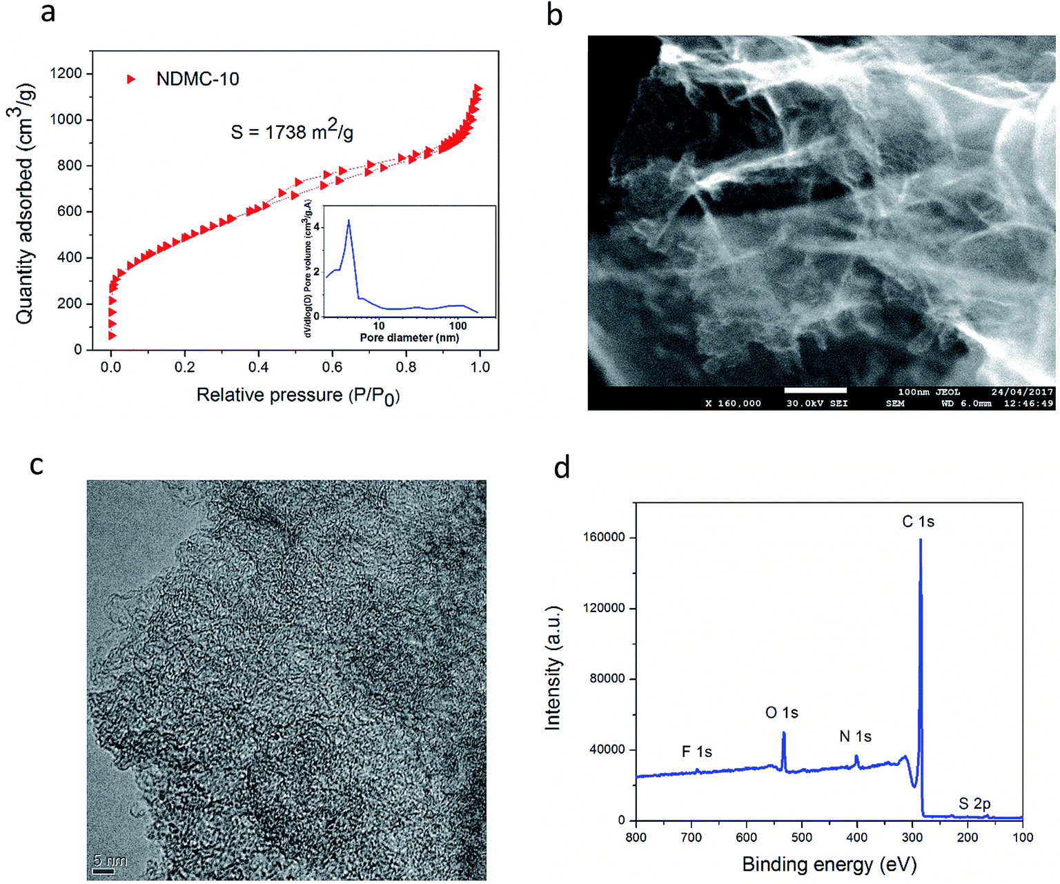 | ||
| Fig. 1 N2 sorption curve of NDMC-10 and pore size distribution (inset) (a), SEM image of NDMC-10 (b), high resolution TEM micrograph of NDMC-10 (c) and XPS survey (d). | ||
The composition of NDMC-10 was analyzed by X-ray photoelectron spectroscopy (XPS). According to the XPS survey in Fig. 1d, the NDMC-10 is a multi-doped carbon material and contains three important heteroatoms in the structure. Nitrogen appears at a moderate doping level around 3.50% and sulfur and fluorine are present at 1.90% and 0.53 wt%, respectively. The high electrochemical activity of sulfur with sodium ions can be expected to introduce faradaic reactions, while fluorine is believed to increase the interlayer distance between the graphene sheets, facilitating the insertion of Na ions during cycling.34
The hybrid device was assembled using NDMC-10 as cathode and sodium metal as anode, the ionic liquid electrolyte was selected to provide an effective and stable anode SEI layer as previously demonstrated.35–37 The capacity of NDMC-10 in the hybrid system was investigated by CV over a potential window of 3.8–0.005 V vs. Na+/Na at a scan rate of 1 mV s−1. After several initial cycles to activate the carbon surface, a voltammogram was recorded and is shown in Fig. 2a. In addition to the expected double layer capacity envelope, the CV shows well-defined peaks in both cathodic and anodic scans. We ascribe the peaks in the CV mainly to Na–sulfur electrochemistry. To elucidate the chemical environment of the sulfur present in the carbon electrode, XPS was carried out at high resolution on the S 2p core level, as depicted in Fig. 2b. The spectrum shows three peaks centred at 164.4, 165.5 and 168.7 eV, respectively. The S 2p3/2 and S 2p1/2 core level peaks at 163.8 and 165.1 eV are ascribed to sulfur covalent bonds (–C–Sx–C, x = 1–2) where sulfur is found, for example, in a thiophene-type structure, whilst the peak at 168 eV is attributed to sulfate/sulfonate (C–SOx–C, x = 2–4) groups and is fitted with a single component representative of both the S 2p3/2 and S 2p1/2 components.38 These results confirm that sulfur has been successfully incorporated into the carbon framework and can be expected to provide redox active sites. As seen in Fig. 2a, the cathodic sweep shows two prominent peaks at 1.8 V and 0.8 V. The peak at 1.8 V is possibly a result of the electrochemical bond cleavage of sulfur bonds (i.e., C–S or disulfide bonds, –S–S–) accompanied by intercalation of sodium ions, similar to the behaviour observed in lithium-based cells when a sulfur-containing material (SCM) was used as a cathode.39–43 As the discharge process continues (cathodic sweep), there is another charge transfer process at 0.8 V which may be related to the reduction of thiophene rings and the further the uptake of sodium ions.44 It is worth mentioning that the cleavage of S–S bonds does not cause a release of the sulfur from the carbon network and the discharge product is not soluble in the electrolyte.45
 | ||
| Fig. 2 Cyclic voltammetry of the hybrid device at 1 mV s−1, (a). XPS S 2p high resolution spectrum of NDMC-10, (b). Rate capability at different current densities, (c). Long-term cycling (3000 cycles) at 1.0 A g−1 (d). | ||
In addition, insertion of Na ions into the structure of NDMC-10 is likely to occur at low potential values.46,47 This can be seen at potentials around 0.1 V where an increasing current appeared. When the scan is reversed, a double layer capacitive contribution with a slight sign of extraction of Na ions are observed at 0.2–1.0 V. Continuing the anodic sweep, a prominent anodic peak around 2.0 V appears, this peak is a result of the reoxidation and reconstruction of S–S bonds. As well as this, two relatively horizontal regions (constant anodic current) are observed, either side of the prominent anodic peak, representing a pure double-layer capacitive contribution; the small bumps may be related to pseudocapacitance from N-functionalities.
To examine the charge-storage capacity of the cell, a fresh cell was subjected to galvanostatic charge–discharge over the same potential range at different current densities (5 cycles for each current), the capacity results are shown in Fig. 2c. In the first cycle at 50 mA g−1, a high discharge capacity (1400 mA h g−1) was observed. The coulombic efficiency of the first cycle is low, indicating the formation of an SEI layer (see Fig. S1† for CV scans as comparison). As cycling proceeds, a capacity of 450 mA h g−1 is observed at the 5th cycle for the small current density (50 mA g−1); subsequent cycles at higher rates show stable behaviour, with capacity values of 420, 340, 300, 230 and 160 mA h g−1 at current densities of 100, 400, 800, 1000, 2000 and 4000 mA g−1, respectively. After cycling the cell at different rates, the first current density was reapplied for 5 further cycles; the capacity obtained was very similar to the earlier capacity (420 mA h g−1), showing that the hybrid system is stable and reversible. Part of this stability is attributed to the ionic liquid electrolyte, which is known to form stable, compact and uniform SEI layers on sodium metal anodes, as demonstrated by Basile et al.36,48
To further demonstrate the superior cycling stability of this hybrid supercapacitor-battery, the same cell used for the tests in Fig. 2c was subjected to 3000 deep cycles at a current density of 1 A g−1 (∼2C). In Fig. 2d we can observe that the discharge capacity remarkably increased over cycling, finishing the last cycle with 520 mA h g−1. This interesting capacity increase is mainly ascribed to the improved wettability of the carbon electrode with cycling, and has been seen previously for negative electrodes in Na-ion batteries with ionic liquid electrolytes.49
The coulombic efficiency (Fig. 2d) is maintained around 100% during the entire 3000 cycles, demonstrating the extraordinary stability of this system. Furthermore, during the long-term cycling presented in Fig. 2d, there is no capacity decay, the capacity slightly fluctuates and returns to its value (∼520 mA h g−1), this is mainly ascribed to the temperature oscillation over the period. This degree of stable cycling is characteristic of pure supercapacitors, but is unique as far as we know for any hybrid or battery-type device.
In Fig. 3a the voltage profiles of the hybrid device at several current densities are shown after 3000 cycles. The overall appearance of the charge/discharge curves is typical of pseudocapacitive-type hybrid devices. During charge, a linear increase is observed from 0.005 V until 1.6 V; this region may be a combination of the capacitive response of the host carbon and the extraction of Na ions from the high-surface area host carbon. At around 1.6–1.7 V, a clear plateau is observed, which is assigned to the dimerization/reconstruction of the S–S bonds as discussed above.40 This potential value correlates well with the prominent peak in the CV curve presented in Fig. 2a. During discharge, a sloping discharge curve can be seen accompanied by two small bumps situated at 1.8 and 1.0 V; these bumps are in good agreement with the CV curve, and are related to the initial cleavage and further reduction reactions of S–S bonds with Na ions, as already discussed. The general shape of the charge and discharge curves does not change as the current density increases; the plateau during charge can still be seen at 5.0 A g−1 (15C), confirming the high reversibility of the system presented here. Similar data at 50 °C for high rate capability (up to 60C, = 1 minute charge/discharge cycling) and cycling stability is presented in Fig. S2.† For comparison purposes only, a control experiment using a standard electrolyte (carbonate-based) is shown in Fig. S3;† as we can see, the capacity obtained is much lower and exhibits continuous capacity fading with no obvious plateau formation.
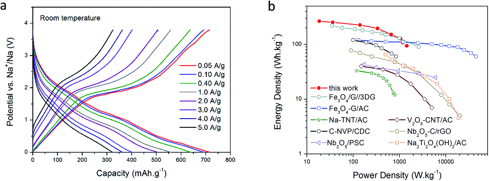 | ||
| Fig. 3 Voltage profiles at different current densities after 3000 cycles at room temperature (a). Ragone plot comparing other Li/Na-ion based hybrid devices (all data at room temperature) (b). | ||
The rate capability of the hybrid after many cycles in ionic liquid medium is remarkable; at an applied current density of 50 mA g−1, a capacity as high as 716 mA h g−1 was obtained, and even at a current density of 5 A g−1 (15C), a capacity of 320 mA h g−1 was retained. This ability to maintain high capacity at high rates is a result of the structure of the NDMC-10 electrode, where the high surface area mesoporous carbon allows rapid access to both capacitive sites as well as to the sulfur and nitrogen functionalities. Estimating energy and power density including a practical mass of Na (refer ESI†) indicates a device power density of 1463 W kg−1 at an energy density of 96 W h kg−1 based on the active materials (both cathode and anode). At a lower power density, energy density rises to 263 W h kg−1. These metrics increase to 270 W h kg−1 and 3822 W kg−1 at 50 °C (refer Fig. S4†) highlighting the excellent combination of a supercapacitor-type cathode with a sodium metal anode in the hybrid device. In addition, the non-flammability of the electrolyte and the absence of dendrites guarantee a safe device with long life. Furthermore, as illustrated in Fig. S2 and S4,† when the device is operated at higher temperature (50 °C), the cell is able to provide more power due to the increased conductivity of the electrolyte. This response further confirms the high stability of this system and introduces a high power Na metal-based energy storage device that can operate at high rates as well as being tolerant of elevated temperature operation.
A Ragone plot summarizing a comparison with literature Li and Na based hybrids is shown in Fig. 3b (further details in ESI†), indicating that the materials of the present work offer the highest energy densities in the performance region below 1000 W kg−1 (corresponding to ∼15C, or a deep discharge in 4 minutes), falling away slightly at higher powers, due to the lower conductivity of the ionic liquid electrolytes. As expected, the performance is significantly extended at elevated temperatures, the 50 °C Ragone plot is shown in Fig. S4.†
It is important to note that the cathode mass loading applied in this work was 0.4 mg cm−2 in order to allow complete characterization of the basic cathode material properties. Several of the publications describing the comparator materials25–30,32,33 shown on the Ragone plot do not provide information on mass loadings and therefore we presume that these are also in a similar range and that the comparison is therefore reasonable. Where loading information is available, and given a wide range of specific capacities, it is more useful to compare areal capacities rather than loading. The NDMC-10 electrodes used in this work have an areal capacity of 0.29 mA h cm−2; this value is comparable to, or higher than other Na-hybrid devices found in the literature (a summary of these values is provided in Table S1†). Further optimization of the binder and application process methodology would allow a thicker layer to be used, if required, for practical application.
To further evaluate and support the Na–S electrochemistry evidenced in Fig. 2a, charged and discharged NDMC-10 electrodes were analyzed after 500 cycles at 2C and disassembly in the glovebox. Both electrodes were purposely not washed to preserve the species formed during cycling. For a robust analysis, XPS was used to reveal the nature of the cathode SEI layer and to show the variation of the oxidation state of sulfur from pristine carbon and cycled NDMC-10 electrodes. Initially, charged and discharged electrodes were transferred to the XPS chamber by using a sealed Ar-filled canister to avoid exposure to air. The electrodes were then etched by using a beam of Ar+ at an accelerating energy of 3 keV and high resolution scans for elements of interest were collected as the etching process proceeded (i.e., a depth profile analysis). In Fig. 4a, the S 2p core level of the discharged (sodiated) electrode is compared during different times of etching (from 0 to 145 min). As shown, before the first etching, the spectrum reveals a prominent peak at 170.5 eV (black line), this peak corresponds to FSI anions from the electrolyte, which was still covering the electrode surface. After 25 min of etching, the new S 2p spectrum shows a slight shift of the FSI− peak to lower binding energies; this shift is ascribed to the decomposition/reduction of FSI− to form the SEI layer and, the electrode is basically covered by this layer from this point on (it is important to note that the NDMC-10 has been cycled to close to Na potential during its 500 cycles). Furthermore, at lower binding energies, a new peak can be observed at 164.2 eV; the appearance of this peak reflects the presence of thiophene–sulfur type structures, meaning that the surface of the carbon electrode has been reached.
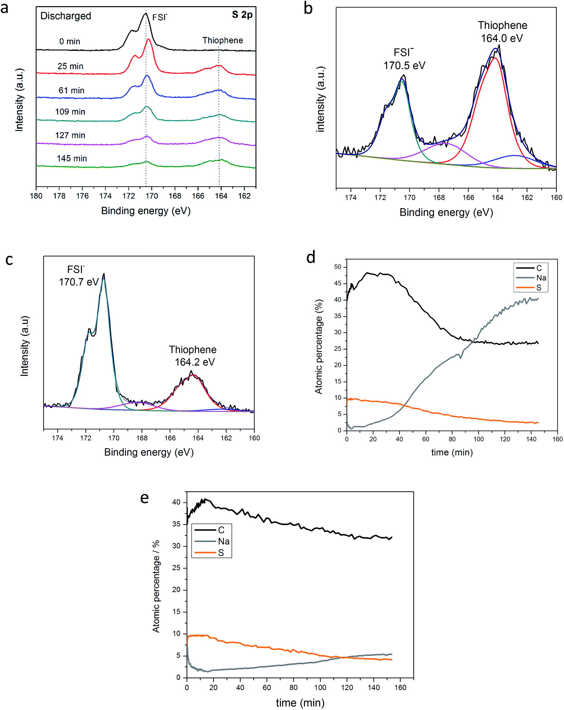 | ||
| Fig. 4 XPS S 2p high resolution spectra of the discharged NDMC-10 electrode as a function of the etching time (a); S 2p fitted high resolution spectrum of the discharged electrode after 145 min of etching (b); S 2p fitted high resolution spectrum of the charged electrode after 145 min of etching (c); concentration profile over time of the discharged electrode (d) and concentration profile over time of the charged electrode (e). | ||
As the etching process continued, no significant difference in the spectra was seen, with the exception of the weakened FSI− peak signal, indicating that the Ar+ ion-beam has successfully removed a substantial amount of the SEI layer from the surface of the electrode.
In order to show the sodiation process taking place during discharge and prove that sulfur was reduced after full discharge, the detailed S 2p spectrum of NDMC-10 is shown separately in Fig. 4b. As can be seen, when fully reduced, the thiophene related peak (S 2p3/2) is now centred at 164.0 eV, this binding energy is lower than the pristine carbon material shown in Fig. 2b, inferring that the oxidation state of sulfur is lowered after being discharged.44 Small shoulders (blue and pink components in Fig. 4b) may indicate some presence of Na2S and Na2S2 type states, respectively. Additionally, the SEI can still be seen due to the presence of the peak at 170.5 eV which is ascribed to the decomposed FSI−. When the same analysis procedure is performed for the charged electrode (Fig. 4c), the S 2p3/2 peak shifts positively to 164.2 eV, suggesting the oxidation of sulfur.
To summarize the XPS analysis of the post-cycled electrodes, we show the concentration profile of carbon, sulfur and sodium over the entire etching profile in Fig. 4d. Interestingly, the concentration of sodium significantly increases with etching time (from 5% to 40%), this directly means that sodium has successfully migrated through the SEI layer and inserted into the carbon framework during discharging (sodiation). On the other hand, as presented in Fig. 4e, the Na concentration for the charged electrode remains below 6% over the entire profile and the concentration does not change significantly over the whole depth profile. These results strongly indicate the important role of Na+ in the high capacity cycling of the NDMC-10 electrode.
Conclusions
We have demonstrated a hybrid electrochemical device using a Na-metal anode and a highly porous N/S co-doped mesoporous carbon cathode. The ionic liquid electrolyte ensured that the “supercapacitor-battery” showed far higher cycling stability against sodium-metal than observed with traditional electrolytes. The chemically-bound sulfur functionalities within the cathode mean that our device can exploit Na–S chemistry in the ionic liquid. With its high capacity at both low and high charge/discharge rates, the hybrid device could be considered a potential component of large scale energy storage technology at both room temperature and 50 °C. It is also easy to manufacture, since the cathode material can be readily obtained from a straightforward method that does not involve transition metal components.Experimental
Electrode materials preparation
The cathode material used in this work is comprised of an N/S-doped mesoporous carbon (NDMC-10), the full synthesis and further details on the material preparation are provided in the ESI.† Our approach to preparing this material was inspired by the work of the Watanabe group who described the preparation of doped carbons from protic ionic liquids.50 In the present case, the protic salt benzimidazole triflate [BIm][TfO] is first synthesized via a proton transfer reaction. The as-obtained [BIm][TfO] salt was ground with calcium citrate as a templating agent in a mass ratio of 1:1. Sodium citrate was then added to the above mixture in a mortar and ground until a homogeneous mixture was obtained, completing a ratio of 1:1:1 of the three different salts.
NDMC-10 was prepared by heating the above mixture in a crucible (alumina) under N2 atmosphere using a tube furnace; the nitrogen flow was 100 mL min−1. The heating rate was 5 °C min−1 and the final temperature was 850 °C. After the furnace reached the final temperature, it was held for an additional 2 h and then was cooled down naturally. The resulting composites (carbon/Ca–Na oxides) were ground and added to hydrochloric acid solution (1 mol L−1) under agitation for 12 h. After dissolution of the oxides, the carbon was filtered and washed several times with pure water until a neutral liquid was achieved. The as-obtained NDMC-10 was collected and dried at 110 °C for 24 h.
For the anode, Na foils were produced from bulk sodium rods stored in paraffin oil (Merck Millipore). For preparation, a piece of sodium was sliced, rolled flat and cleaned carefully with hexane with the aid of a nylon brush. All procedures were carried out under an argon environment inside a glove box. The electrolyte consisted of sodium bis(fluorosulfonyl)imide (NaFSI, Solvionic) dissolved in the ionic liquid N-propyl-N-methyl pyrrolidinium bis(fluorosulfonyl) imide (C3mpyrFSI, Solvionic), the concentration of the final electrolyte was 0.8 mol NaFSI per kg. For the control experiment, a solution of 1 M NaClO4 in ethylene carbonate/diethyl carbonate (EC/DEC, 1:1 vol.) was used.
Characterization methods
Field emission scanning electron microscopy (FEG-SEM) was performed on a JEOL JLM 7001-F microscope. Transmission electron microscopy (TEM) was run using a FEI Tecnai G2 T20 with an accelerating voltage of 200 kV. X-ray photoelectron spectroscopy (XPS) measurements were carried out using an AXIS Ultra (Kratos Analytical). N2 adsorption/desorption was measured by a Tristar II volumetric adsorption analyzer at 77 K (Micromeritics). Before the measurements, the samples were degassed under vacuum (p < 10–5 mbar) at 373 K for 6 h. The Brunauer–Emmett–Teller (BET) equation was used to calculate the specific surface area from adsorption data. The total volume of pores was calculated from the amount of nitrogen adsorbed at P/P0 = 0.99. The pore size distributions were calculated by analyzing the adsorption branch of the N2 sorption isotherm using the Barret–Joyner–Halenda (BJH) procedure.Electrochemical methods
NDMC-10 electrodes were fabricated by using the slurry coating method (refer to ESI†). The hybrid device was assembled in coin cells (CR 2032-type, Osaka, Japan) using NDMC-10 and Na foil as positive and negative electrodes, respectively. The cell was completed by sandwiching a pre-wet glass fiber separator with the electrolyte (GF/A, Whatman) between the electrodes, then pressing. Electrochemical characterization was performed on a multi-channel potentiostat (VMP-2 Princeton applied research) when cyclic voltammetry (CV) was used. For long term-cycling and capacity measurements of the cells, the galvanostatic charge–discharge was employed by using the multi-channel battery tester (Neware BST 4000, China). Discharge energy calculations are based on the directly measured discharge energy as a function of time. Power calculations are average power over the whole discharge. As the discharge energy is close to linear in time, the power is approximately constant over the whole discharge.Conflicts of interest
There are no conflicts to declare.Acknowledgements
This work was funded by the Australian Research Council under the discovery schemes (DP130101652 and DP160101178). MF and DRM are grateful to the ARC for funding through the Australian Laureate Fellowship program. DRM's Laureate Project (FL120100019) also supported aspects of the work.Notes and references
- J. M. Tarascon and M. Armand, Nature, 2001, 414, 359–367 CrossRef CAS PubMed.
- T. M. Bandhauer, S. Garimella and T. F. Fuller, J. Electrochem. Soc., 2011, 158, R1–R25 CrossRef CAS.
- K. Kubota and S. Komaba, J. Electrochem. Soc., 2015, 162, A2538–A2550 CrossRef CAS.
- T. H. Hwang, D. S. Jung, J. S. Kim, B. G. Kim and J. W. Choi, Nano Lett., 2013, 13, 4532–4538 CrossRef CAS PubMed.
- B. E. Conway, Electrochemical Supercapacitors: Scientifical Fundamentals and Technological Applications, Kluwer Academic/Plenum, New York, 1999 Search PubMed.
- P. Simon and Y. Gogotsi, Nat. Mater., 2008, 7, 845–854 CrossRef CAS PubMed.
- G. Wang, L. Zhang and J. Zhang, Chem. Soc. Rev., 2012, 41, 797–828 RSC.
- G. A. Ferrero, M. Sevilla and A. B. Fuertes, Sustainable Energy & Fuels, 2017, 1, 127–137 CAS.
- A. Burke, Electrochim. Acta, 2007, 53, 1083–1091 CrossRef CAS.
- J. Yan, Q. Wang, T. Wei, L. Jiang, M. Zhang, X. Jing and Z. Fan, ACS Nano, 2014, 8, 4720–4729 CrossRef CAS PubMed.
- J. P. Zheng, P. J. Cygan and T. R. Jow, J. Electrochem. Soc., 1995, 142, 2699–2703 CrossRef CAS.
- M. R. Lukatskaya, O. Mashtalir, C. E. Ren, Y. Dall'Agnese, P. Rozier, P. L. Taberna, M. Naguib, P. Simon, M. W. Barsoum and Y. Gogotsi, Science, 2013, 341, 1502–1505 CrossRef CAS PubMed.
- O. Ghodbane, J. L. Pascal and F. Favier, ACS Appl. Mater. Interfaces, 2009, 1, 1130–1139 CAS.
- V. Augustyn, J. Come, M. A. Lowe, J. W. Kim, P.-L. Taberna, S. H. Tolbert, H. D. Abruña, P. Simon and B. Dunn, Nat. Mater., 2013, 12, 518–522 CrossRef CAS PubMed.
- M. R. Lukatskaya, B. Dunn and Y. Gogotsi, Nat. Commun., 2016, 7, 12647 CrossRef PubMed.
- Y. Diao, K. Xie, S. Xiong and X. Hong, J. Power Sources, 2013, 235, 181–186 CrossRef CAS.
- M. Barghamadi, A. S. Best, A. I. Bhatt, A. F. Hollenkamp, P. J. Mahon, M. Musameh and T. Ruther, Electrochim. Acta, 2015, 180, 636 CrossRef CAS.
- Y. Shao, F. Ding, J. Xiao, J. Zhang, W. Xu, S. Park, J.-G. Zhang, Y. Wang and J. Liu, Adv. Funct. Mater., 2013, 23, 987–1004 CrossRef CAS.
- J. Xie, Q. Dong, I. Madden, X. Yao, Q. Cheng, P. Dornath, W. Fan and D. Wang, Nano Lett., 2015, 15, 8371–8376 CrossRef CAS PubMed.
- I. Kim, J.-Y. Park, C. H. Kim, J.-W. Park, J.-P. Ahn, J.-H. Ahn, K.-W. Kim and H.-J. Ahn, J. Power Sources, 2016, 301, 332–337 CrossRef CAS.
- S. Xin, Y. X. Yin, Y. G. Guo and L. J. Wan, Adv. Mater., 2014, 26, 1261–1265 CrossRef CAS PubMed.
- N. Zhao, C. Li and X. Guo, Phys. Chem. Chem. Phys., 2014, 16, 15646–15652 RSC.
- H. Yadegari, Q. Sun and X. Sun, Adv. Mater., 2016, 28, 7065–7093 CrossRef CAS PubMed.
- T. C. Mendes, C. Xiao, F. Zhou, H. Li, G. P. Knowles, M. Hilder, A. Somers, P. C. Howlett and D. R. MacFarlane, ACS Appl. Mater. Interfaces, 2016, 8, 35243–35252 CAS.
- J. Yin, L. Qi and H. Wang, ACS Appl. Mater. Interfaces, 2012, 4, 2762–2768 CAS.
- Z. Chen, V. Augustyn, X. Jia, Q. Xiao, B. Dunn and Y. Lu, ACS Nano, 2012, 6, 4319–4327 CrossRef CAS PubMed.
- B. Babu and M. M. Shaijumon, J. Power Sources, 2017, 353, 85–94 CrossRef CAS.
- R. Thangavel, K. Kaliyappan, K. Kang, X. Sun and Y.-S. Lee, Adv. Energy Mater., 2016, 6, 1502199 CrossRef.
- E. Lim, C. Jo, M. S. Kim, M.-H. Kim, J. Chun, H. Kim, J. Park, K. C. Roh, K. Kang, S. Yoon and J. Lee, Adv. Funct. Mater., 2016, 26, 3711–3719 CrossRef CAS.
- H. Li, Y. Zhu, S. Dong, L. Shen, Z. Chen, X. Zhang and G. Yu, Chem. Mater., 2016, 28, 5753–5760 CrossRef CAS.
- L. Yu and G. Z. Chen, Faraday Discuss., 2016, 190, 231–240 RSC.
- F. Zhang, T. Zhang, X. Yang, L. Zhang, K. Leng, Y. Huang and Y. Chen, Energy Environ. Sci., 2013, 6, 1623–1632 CAS.
- S. Zhang, C. Li, X. Zhang, X. Sun, K. Wang and Y. Ma, ACS Appl. Mater. Interfaces, 2017, 9, 17136–17144 CAS.
- P. Wang, B. Qiao, Y. Du, Y. Li, X. Zhou, Z. Dai and J. Bao, J. Phys. Chem. C, 2015, 119, 21336–21344 CAS.
- H. Usui, Y. Domi, M. Shimizu, A. Imoto, K. Yamaguchi and H. Sakaguchi, J. Power Sources, 2016, 329, 428–431 CrossRef CAS.
- M. Forsyth, G. M. A. Girard, A. Basile, M. Hilder, D. R. MacFarlane and F. Chen, Electrochim. Acta, 2016, 220, 609–617 CrossRef CAS.
- M. Forsyth, H. Yoon, F. Chen, H. Zhu, D. R. MacFarlane, M. Armand and P. C. Howlett, J. Phys. Chem. C, 2016, 120, 4276–4286 CAS.
- Y. Yan, Y.-X. Yin, S. Xin, Y.-G. Guo and L.-J. Wan, Chem. Commun., 2012, 48, 10663–10665 RSC.
- X. Yu, J. Xie, Y. Li, H. Huang, C. Lai and K. Wang, J. Power Sources, 2005, 146, 335–339 CrossRef CAS.
- X. Yu, J. Xie, J. Yang, H. Huang, K. Wang and Z. Wen, J. Electroanal. Chem., 2004, 573, 121–128 CAS.
- J. Fanous, M. Wegner and J. Grimminger, Chem. Mater., 2011, 23, 5024–5028 CrossRef CAS.
- S. J. Visco, M. Liu, M. B. Armand and L. C. de Jonghe, Mol. Cryst. Liq. Cryst., 1990, 190, 185–195 CrossRef CAS.
- S. J. Visco, C. C. Mailhe, L. C. De Jonghe and M. B. Armand, J. Electrochem. Soc., 1989, 136, 661–664 CrossRef CAS.
- L. Fan, R. Ma, Y. Yang, S. Chen and B. Lu, Nano Energy, 2016, 28, 304–310 CrossRef CAS.
- Y.-X. Wang, B. Zhang, W. Lai, Y. Xu, S.-L. Chou, H.-K. Liu and S.-X. Dou, Adv. Energy Mater., 2017, 7, 1602829 CrossRef.
- E. Irisarri, A. Ponrouch and M. R. Palacin, J. Electrochem. Soc., 2015, 162, A2476–A2482 CrossRef CAS.
- S. Komaba, W. Murata, T. Ishikawa, N. Yabuuchi, T. Ozeki, T. Nakayama, A. Ogata, K. Gotoh and K. Fujiwara, Adv. Funct. Mater., 2011, 21, 3859–3867 CrossRef CAS.
- A. Basile, F. Makhlooghiazad, R. Yunis, D. R. MacFarlane, M. Forsyth and P. C. Howlett, ChemElectroChem, 2017, 4, 986–991 CrossRef CAS.
- I. Hasa, S. Passerini and J. Hassoun, J. Power Sources, 2016, 303, 203–207 CrossRef CAS.
- S. Zhang, K. Dokko and M. Watanabe, Chem. Mater., 2014, 26, 2915–2926 CrossRef CAS.
Footnote |
| † Electronic supplementary information (ESI) available. See DOI: 10.1039/c7se00547d |
| This journal is © The Royal Society of Chemistry 2018 |