Lignin-first biorefinery: a reusable catalyst for lignin depolymerization and application of lignin oil to jet fuel aromatics and polyurethane feedstock†
Yong
Huang‡
 ,
Yijing
Duan‡
,
Shi
Qiu‡
,
Meng
Wang
,
Chao
Ju
,
Hui
Cao
,
Yunming
Fang
,
Yijing
Duan‡
,
Shi
Qiu‡
,
Meng
Wang
,
Chao
Ju
,
Hui
Cao
,
Yunming
Fang
 * and
Tianwei
Tan
National Energy Research Center for Biorefinery, Beijing University of Chemical Technology, 100029, Beijing, China. E-mail: fangym@mail.buct.edu.cn
First published on 19th December 2017
Abstract
Lignin-first biorefinery is a novel concept, which was developed recently with great potential. This paper addresses two important issues in the lignin-first biorefinery: catalyst regenerability and lignin depolymerized product application. It was found that SiC is an effective and regenerable catalyst support, and the catalytic performance of Ru/SiC is comparable to the state-of-the-art results obtained from Ru/C used in the lignin-first biorefinery under identical conditions. Furthermore, the Ru/SiC catalyst can be regenerated by calcination without decrease in the catalytic performance. The resulting lignin oil from Ru/SiC catalyzed lignin depolymerization was then extracted by hexane, which is an optimized solvent for lignin oil upgradation based on model compound screening, and around 50 wt% of the hexane extract was obtained. The hexane extract was converted into aromatic hydrocarbons by ambient pressure hydrodeoxygenation over MoO3 catalyst. With a 15% blend of the resulting aromatic hydrocarbons, the jet fuel from the hydroprocessed ester and fatty acid (HEFA) meets the density requirements of the ASTM 7566 standard without compromising other required properties. The residue from hexane extraction was successfully used for preparation of rigid polyurethane foam (RPF) as an alternative to polyols of up to 50 wt%. The lignin based RPF not only reduced the use of fossil derived polyols, but also resulted in better water and flame resistance based on tentative LOI assessments. A biorefinery system was then proposed based on the technology developed in the present study.
1. Introduction
Lignin is a three-dimensional amorphous polymer consisting of methoxylated phenylpropane units and their derivatives. It accounts for about 15–35 wt% of lignocellulosic biomass and can potentially serve as an abundant renewable resource for the production of fuels and chemicals.1–4Large quantities of lignin are currently being generated and processed by the pulping and paper industry. It is also expected that the lignin amount will significantly increase with the ongoing development of biorefineries, such as second-generation biofuel production.3 Numerous lignin conversion efforts, including gasification, pyrolysis, and selective depolymerization, have been reported and summarized in several excellent review papers.5–14 However, the processing of lignin is still a challenge task in a biorefinery, part of which was attributed to the structural change during biomass pretreatments.15–20 During some of those pretreatments such as acid/base hydrolysis, the decrease in ether bonds of lignin and subsequent formation of new C–C linkages generally takes place, which results in difficulty in depolymerization and utilization of the resulting lignin.21
Recently, a new concept called lignin-first refinery, different from the common cellulose-first refinery, was proposed and extensively studied.22–24 The concept proposed that lignin was processed in its most reactive and workable form. Ferrini et al.25 proposed a RANEY® Ni and isopropanol/water solvent catalytic system with isopropanol as the hydrogen donor. High degrees of delignification and carbohydrate retention in the pulp as well as the enzymatic processing of the pulp were demonstrated. The results, however, also show the complexity of the low-molecular-weight lignin product mixture. Parsell et al.26 presented a selective hydrogenolysis of protolignin with Zn modified Pd nanoparticles on carbon with external H2, focusing on the lignin monomers and the enzymatic conversion of the retained pulp. Bosch et al.27 then reported the production of lignin monomer by catalytic depolymerization of wood over Ru/C with methanol as the solvent. Structural information of dimeric products and their potential application as polymer precursors were also demonstrated. Based on the above examples, lignin is successfully converted into low-molecular-weight phenolic products in the so-called lignin-first biorefinery. Another benefit of the lignin-first biorefinery is that it preserves most of the C9 basic structure in the original lignin composition, which improves the carbon atomic efficiency; also, it has the potential to produce jet fuel that generally comprises C9–C15 carbons.
However, several important obstacles still need to be addressed for a practical lignin-first biorefinery: (1) carbon is generally used as the catalyst support in such a lignin-first biorefinery, leading to difficulties in regeneration of the catalyst by the prevalent methods, such as calcination; (2) the application of depolymerized lignin should be carefully designed to replace urgent and important products in present chemical industries; and (3) hemicellulose is prone to degradation in the biorefinery and thus solubilized in the lignin oil. This requires additional separation of products from hemicellulose-derived C5 sugars and lignin-derived phenols, which is usually difficult and costly. The above-mentioned obstacles can be avoided by catalyst development and molecular engineering directed product development.28
With respect to catalysts, a support with high thermal and oxidation stability is of vital importance to obtain a regenerable catalyst. SiC exhibits a high thermal/oxidation stability and is thus a calcinable catalyst support. One major limitation of SiC as a catalyst support material is the low surface area;29 however, there have been several methods to synthesize SiC with high surface area (more than 10 m2 g−1). For example, Liu et al.30 reported a low-temperature synthetic method for mesoporous SiC via reaction of mesoporous carbon and silicon powders. Hoffmann et al.31 reported the synthesis of SiC using a hard template as the support of Ni/SiC catalyst, which exhibits higher conversion in reforming of methane than using SiO2 as a support. It is thus interesting to test the possibility of SiC as a catalyst support in the lignin-first biorefinery.
From the viewpoint of products, it is highly interesting to develop the product according to the properties of the resulting lignin oil.23 As mentioned above, a series of low-molecular-weight phenolic products (including monomer and oligomer structures) can be obtained with well-reversed C9 basic structures. The C9 aromatic backbones and hydroxyl functional groups lead to two potential applications of the lignin oil: production of jet fuel range aromatic hydrocarbons and replacement of polyols in polymer industry. Jet fuel is a very complex mixture of paraffins, iso-paraffins, cycloparaffins, and aromatic hydrocarbons. Up to 25 vol% of aromatic hydrocarbons in jet fuel play an important role for balancing density and other necessary properties.32 However, the well-developed strategies for biomass-derived jet fuel production including biomass gasification followed by Fischer–Tropsch synthesis (FTS) and triglyceride hydrodeoxygenation (HDO) generate mainly paraffins and iso-paraffins.33 Conversion of lignin to aromatic hydrocarbons is thus an important supplement for the production of biomass-derived jet fuel. After successful depolymerization of lignin to oil, aromatic hydrocarbons can be obtained by HDO of the lignin oil, especially the phenolic monomers. HDO processes for phenolic compounds are challenging since high yields of aromatics can only be achieved by selectively cleaving the strong Caryl–O bond without hydrogenating the aromatic ring. Also, typical hydrogenation catalysts in the oil refinery reveal clear challenges during bio-oxygenate processing.34–41 Recently, researchers have demonstrated that MoO3 is an attractive and earth-abundant catalyst active for the HDO of various biomass-derived oxygenates including aliphatic and cyclic ketones, furans, and phenols under low H2 pressure.41–43 Hence, integration of lignin depolymerization and the resulting oil upgradation by MoO3 is a potentially promising route for production of jet fuel.
Besides the HDO of lignin-derived phenols into hydrocarbons, the hydroxyl-group-rich lignin oil can also be widely applied in the polymer industry. Rigid polyurethane foam (RPF), a highly cross-linked polymer, is characterized by its versatility because of its low density, low moisture permeability, low thermal conductivity, and high dimensional stability.44 RPF represents one of the most promising energy saving insulation materials in construction, refrigeration appliances, and other applications. The raw materials for RPF production are polyols and isocyanates, which are currently dependent on petrochemical products. Due to the rapid depletion of petroleum reserves, the replacement of petroleum-based polyols by bio-based polyols has become increasingly popular. However, the properties of the resulting RPF highly rely on the hydroxyl group types in polyols. A mixture of polyols with different hydroxyl group types is thus preferred.45 Considering the abundance of various phenolic and aliphatic hydroxyl groups in lignin basic structures, the lignin oil in general and the phenolic dimers/oligomers in particular can be good alternatives for the polyols. Furthermore, lignin derived RPF is more biodegradable and environmentally friendly than the petroleum derived one.46
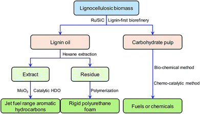
Based on the above considerations, our study reports on the development of a biorefinery system conceptually shown in Fig. 1. The research in this paper focuses on the development of a regenerable catalyst in a lignin-first biorefinery and application of lignin oil in jet fuel and RPF production.
2. Experimental
2.1. Materials
The following chemicals were used as-received without further purification. 5% ruthenium on carbon (5% Ru/C) was acquired from Tokyo Chemical Industry Co. Ltd. RuCl3 (99%) was purchased from Alfa-Aesar. SiC nanofibers prepared by chemical vapor deposition were provided by Sinet Advance Materials Co., Ltd. Molybdenum trioxide (MoO3), polyphenylmethane polyisocyanate (PAPI), polyether polyol 5110, triethylene diamine, stannous octoate, BYK-9955, methanol, hexane, acetone, dichloromethane (DCM), anisole, creosol, eugenol, and 4-allylsyringol were purchased from Sigma Aldrich. The biomass sample was apple wood (a type of hardwood), which was ground to less than 0.38 mm and dried at 80 °C for 24 h. The elemental composition and contents of lignin, extractives, and ash are shown in Table 1.2.2. Preparation of catalysts
The SiC support was sieved to 0.25–0.38 mm. The Ru/SiC catalyst with 5 wt% Ru was prepared in by incipient-wetness impregnation. The RuCl3 was used as the precursor for the catalyst. Following the impregnation, the solid was dried at 100 °C overnight and calcined under a H2 atmosphere at 400 °C for 3 h.2.3. Catalyst characterization
X-ray diffraction (XRD) measurements were carried out using a Bruker diffractometer with Cu radiation (40 kV, 120 mA), data were recorded in the 2θ range of 5–50° with an angular step size of 0.05° and a counting time of 8 s per step.Scanning electron microscopy (SEM) was carried out using a HITACHI S-4700 microscope. Samples were prepared by dusting the catalyst powder onto double-sided carbon tape, mounted on a copper stub. The samples were subsequently sputter coated with a thin gold film to reduce charging effects.
Transmission electron microscopy (TEM) was obtained with a FEI Tecnai G2 20 S twin microscope operated at 200 kV. The sample was dispersed in ethanol, and deposited on a holey film supported on a lacey support film.
X-ray photoelectron spectroscopy (XPS) was conducted using a Thermo Fisher ESCALAB 250 utilizing monochromatic Al Kα radiation. High-resolution and survey scans were performed at pass energies of 30 and 200 eV, respectively.
GC/MS analysis was carried out with Agilent 7890A/5975C system equipped with a HP-5 MS column. The temperature program of the column was as follows: temperature maintained at 50 °C for 1 min, heating to 300 °C at a rate of 5 °C min−1, and temperature maintained at 300 °C for 4 min. The interpretation of the mass spectra was mainly based on an automatic library search (NIST11, version 2.0).
2D HSQC NMR spectra were acquired at 25 °C in acetone-d6 with a Bruker AVANCE spectrometer (600 MHz). The spectral widths of 1H and 13C dimensions were 20 ppm using 2048 data points for an acquisition time (AQ) of 128 ms and 219 ppm using 512 increments (AQ of 11.6 ms), respectively.
2.4. Catalytic depolymerization of lignin in woody biomass
Apple wood (15.0 g), Ru/C or Ru/SiC (2.25 g), and methanol (300 mL) were added to a stainless steel autoclave (500 mL). After the air in the reactor was replaced with H2 3 times, the reactor was pressurized with H2 to 1 MPa at room temperature. It was then heated to 250 °C for 3 h at a heating rate of 1.6 °C min−1 and 700 rpm stirring. The working pressure was 10.5 MPa. After the autoclave cooled to room temperature, the resulting mixture was filtered to liquid and solid phases. The liquid phase was analyzed by GC/MS and further extracted by hexane to supply monomer- (extract) and dimer/oligomer-rich (residue) phases. In some cases, different reaction conditions were used as specified in the table or figure legends.After depolymerization of protolignin in apple wood, the Ru/SiC and holocellulose mixture was subjected to cellulose hydrolysis according to the experimental methods in the ESI† to remove the holocellulose. After that, the dried solid residue was calcined at 550 °C with a rate of 5 °C min−1 and held for 1 h. The regenerated catalyst with a trace amount of ash was directly used for the next run under the same reaction conditions as lignin depolymerization.
2.5. Catalytic HDO of bio-oil over MoO3
The HDO experiments were performed in a stainless steel fixed bed reactor (I.D., 14 mm; length, 600 mm), which was heated by an insulated furnace. 5 g of MoO3 (0.38–0.83 mm) was placed in the middle of the reactor, where the temperature was maintained at 350 °C. Liquid samples were introduced into the reactor at 0.2 mL min−1via a syringe pump. Reactant gas H2 was mixed with vaporized sample at the inlet of the reactor, and the total gas flow rate was kept at 500 mL min−1. All experiments were performed under atmospheric pressure.2.6. Preparation of RPF with hexane residue replacing polyol
The preparation was conducted in a 500 mL four-necked flask equipped with a reflux condenser, mechanical stirrer, thermometer, and nitrogen gas inlet. Polyether polyol and a given mass fraction of hexane residue (0, 10, or 50 wt%) were added into the flask and heated at 110 °C for 2 h. After cooling to room temperature, triethylene diamine, silicone oil, BYK-9955, and stannous octoate were added to the flask and stirred for 2 h. A pre-calculated amount of polymeric PAPI was then added into the flask and rapidly mixed with them. RPF was finally formed by pouring the resulting mixture into a preheated standard mold under the condition of 50 °C plate vulcanizing machine for 30–50 min. After stripping, RPF was allowed to cure at room temperature for at least 48 h. The RPFs produced with different mass fractions of hexane residue (0, 10, and 50 wt%) were referred to as L0PU, L10PU, and L50PU, respectively. The RPF obtained was subjected to comprehensive characterization with the methods detailed in the experimental section of the ESI.†3. Results and discussion
3.1. Depolymerization of lignin in apple wood over Ru/SiC
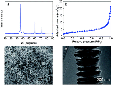 | ||
| Fig. 2 Characterization of SiC nanofibers. (a) XRD pattern; (b) nitrogen adsorption–desorption isotherm; (c) SEM image; (d) TEM image. | ||
| Samples | S BET (m2 g−1) | Pore volume (cm3 g−1) | Average diameter (nm) |
|---|---|---|---|
| SiC | 10.10 | 0.03 | 13.03 |
| Ru/SiC | 7.95 | 0.03 | 12.74 |
| C | 775.69 | 0.52 | 2.68 |
| Ru/C | 648.25 | 0.76 | 4.74 |
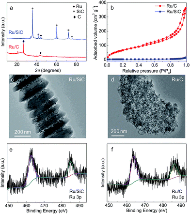
After Ru deposition, the crystalline structure and textural properties are studied by powder XRD (Fig. 3a) and low-temperature nitrogen adsorption analyses (Fig. 3b and Table 2). As for the Ru/SiC catalyst, a diffraction peak was observed at 2θ = 44°, which was attributed to Ru (JCPDS 060663) nanoparticles.51 However, no characteristic diffraction peaks of Ru species were detected on Ru/C, which indicates that the particle size of Ru deposited on carbon was smaller than that on SiC and even than the XRD detection limit. TEM images of Ru/SiC in Fig. 3c and S1 (ESI†) show a high dispersion of Ru with a slight agglomeration. However, the particle size of Ru in Ru/SiC was much larger than that in commercial Ru/C (Fig. 3d and S1†), which is in good agreement with the XRD results. The Ru/SiC and Ru/C catalysts showed similar XPS spectra (Fig. 3e and f). Doublet peaks assigned to Ru 3p3/2 and Ru 3p1/2 were found in both spectra. The XPS results indicated that the Ru species are mainly present as metallic Ru0.52
In summary, commercially available SiC nanofibers with a surface area of 10 m2 g−1 are an effective support for Ru dispersion. Though the dispersion of Ru over SiC is lower than that over carbon due to the low surface area, the Ru metal generally maintains a high dispersion state.
| Entry | Catalyst (g) | Temperature (°C) | T (h) | Oil (wt%) | Delignificationf (wt%) | Monomer (wt%) |
|---|---|---|---|---|---|---|
| a Reaction conditions: 10 g of apple wood (particle size of <0.38 mm), 1.5 g of Ru/SiC, 200 mL of methanol, 1 MPa H2 at room temperature, and 3 h. Reaction pressure is approximately 11 MPa. b Reaction with Ru/C catalyst. c Reaction with SiC support. d Reaction pressure is 4 MPa. e Reaction pressure is 6.5 MPa. f Based on the weight of the DCM extracted fraction and Klason lignin weight. | ||||||
| 1 | — | 250 | 3 | 24.4 | 72.9 | 9 |
| 2b | 1.5 | 250 | 3 | 35.6 | 89.5 | 47 |
| 3c | 1.5 | 250 | 3 | 25.8 | 73.9 | 10 |
| 4 | 1.5 | 250 | 3 | 36.2 | 90.0 | 48 |
| 5 | 1.5 | 250 | 0.5 | 28.7 | 76.2 | 31 |
| 6 | 1.5 | 250 | 6 | 36.8 | 91.7 | 47 |
| 7d | 1.5 | 200 | 3 | 19.9 | 57.4 | 16 |
| 8e | 1.5 | 225 | 3 | 25.4 | 74.3 | 31 |
| 9 | 0.5 | 250 | 3 | 28.5 | 75.8 | 33 |
| 10 | 3.0 | 250 | 3 | 36.1 | 91.3 | 48 |
When the SiC support was employed, the catalytic performance was very similar to that obtained by the blank experiment, indicating that SiC itself exhibits negligible catalysis (entry 3, Table 3). Subsequently, in terms of delignification and monomer yield, Ru/SiC exhibited a promising catalytic performance, which was comparable to that of Ru/C (entry 4, Table 3). These results indicated that the SiC support is very suitable for the lignin-first biorefinery.
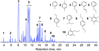
The composition of the liquid was further investigated by GC/MS. Fig. 4 shows the total-ion chromatograms (TICs) of the products obtained from the Ru/SiC and Ru/C catalytic systems. The major products obtained from both systems mainly contained guaiacol (G1 and G2) and syringol (S1–S8) lignin subunits. Propylguaiacol (G2) and 4-n-propylsyringol (S4) were concentrated in the Ru/C system, while the relative contents of most compounds were likely homogeneous in the Ru/SiC system. In other words, the cleavage of the propyl side chain in G2 and S4 compounds easily occurred in the Ru/SiC system.
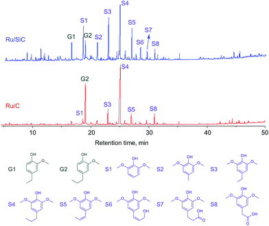 | ||
| Fig. 4 Total-ion chromatograms (TICs) of liquid obtained from depolymerization of protolignin in apple wood at 250 °C for 3 h with 1 MPa H2 using Ru/SiC and Ru/C catalysts. | ||
The effect of reaction time was studied and the results showed that 0.5 h was not enough for the lignin conversion with a relatively low delignification and monomer yield. However, it was difficult to further increase the delignification and monomer yield with a reaction time longer than 3 h (entries 5 and 6, Table 3), suggesting that 3 h was the optimal reaction time. The effect of temperature on lignin conversion was also investigated. The catalytic performance of Ru/SiC improved with an increase in temperature from 200 to 250 °C (entries 7–8, Table 3). In addition, the lower dosage of the catalyst could not afford complete lignin conversion with the delignification degree and monomer yield being 75.8% and 33%, respectively, and double dosage provided similar delignification degree and monomer yield as those from the run using the typical dosage (entries 9 and 10, Table 3).
It can be concluded from the above results that Ru/SiC provides catalytic performances in protolignin depolymerization similar to Ru/C, though the dispersions of Ru in these two catalysts are different. The basic mechanistic events in the lignin-first biorefinery are generally recognized as lignin solubilization, depolymerization, and stabilization.22 A recent study56 reported that the solvent employed in the biorefinery mainly contributes to lignin solvolysis including extraction of lignin from the parent biomass and further depolymerization to small reactive intermediates, while the catalyst (and H2) is responsible for the stabilization of the resulting reactive intermediates and prevents undesirable repolymerization. Hence, it seems that both Ru/SiC and Ru/C play similar roles in the stabilization of reactive intermediates under the applied conditions.
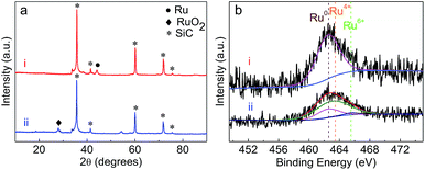 | ||
| Fig. 5 (a) XRD patterns of (i) fresh Ru/SiC and (ii) Ru/SiC regenerated by calcination; (b) XPS spectra of Ru 3p in the (i) fresh Ru/SiC and (ii) Ru/SiC regenerated by calcination. | ||
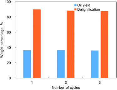
As shown in Table 1, the ash content of apple wood was lower than 1.0 wt%. The effect of such a low yield of ash on catalyst performance was then tested using the calcined catalyst but without removal of the ash. In order to understand the effect of ash, the contents of some typical metals (K, Ca, Na, Mg, and Al) deposited on the regenerated catalysts were subjected to ICP analysis. As listed in Table 4, no obvious change in the contents of those metals on the regenerated Ru/SiC was found. In terms of the catalytic performance, it was interesting to find that the oil yield and delignification from depolymerization of protolignin in apple wood was constant during the three cycles of Ru/SiC reuse (see Fig. 6). The change in the product distribution of the liquid products (Fig. S2 in the ESI†) was also insignificant. This indicated that the low ash content in apple wood had a negligible influence on the catalytic performance and Ru/SiC could be easily regenerated by calcination in the lignin-first biorefinery.
| Sample | Metal content (wt%) | ||||
|---|---|---|---|---|---|
| Na | K | Mg | Ca | Al | |
| Apple wood | 0.08 | 0.10 | 0.05 | 0.32 | 0.02 |
| Ru/SiC after 1st run | 0.03 | 0.02 | <0.01 | 0.11 | <0.01 |
| Ru/SiC after 2nd run | 0.03 | 0.02 | 0.01 | 0.19 | <0.01 |
3.2. Ambient pressure upgradation of hexane extract
The liquid obtained from the lignin-first biorefinery had different solubilities in different solvents. The liquid was completely soluble in acetone, but only around 80 wt% of liquid was soluble in DCM and 50 wt% in hexane. Hence, we first tested the influence of different solvents on the catalytic performance on HDO of lignin oil over MoO3. Eugenol was used as a model compound in this study. The concentration of eugenol in solvent was kept at 10 wt%. The catalytic performance is shown in Table 5. When DCM was used as solvent, it self-decomposed under the experimental conditions. The collected products showed high acidity, which was mostly likely due to the presence of dissolved HCl in the product, where Cl came from the DCM solvent. GC/MS analysis indicated that the eugenol was not converted when DCM was used as the solvent. When acetone was used as the solvent, a severe competitive effect between eugenol and acetone was observed since the acetone could be hydro-deoxygenated into propylene over MoO3. Such a competitive effect resulted in low aromatics yield from the phenolic structure. However, an interesting synergistic effect was found when hexane was used as the solvent, and the eugenol conversion and aromatics yield was much higher than those without the solvent.| a The liquid flow rate is 0.02 mL min−1. | |||||
|---|---|---|---|---|---|
| Solvent | Hexane | Tetradecane | DCM | Acetone | Nonea |
| Conversion, % | 100 | 100 | 5 | 99 | 62 |
| Selectivity to HCs, % | 100 | 97 | 0 | 18 | 61 |
| Yields, % | |||||
| HCs | |||||
| Benzene | 2 | 0 | 0 | 0 | 1 |
| Toluene | 3 | 1 | 0 | 0 | 1 |
| Xylene | 3 | 1 | 0 | 0 | 2 |
| Trimethylbenzene | 1 | 1 | 0 | 2 | 1 |
| Propylbenzene | 52 | 43 | 0 | 6 | 34 |
| p-Propyltoluene | 27 | 27 | 0 | 2 | 17 |
| p-Dipropylbenzene | 1 | 2 | 0 | 0 | 2 |
| Other HCs | 11 | 21 | 0 | 7 | 7 |
| Oxygenates | |||||
| Phenol | 0 | 0 | 0 | 0 | 0 |
| Methylphenol | 0 | 0 | 0 | 0 | 0 |
| Propylphenol | 0 | 2 | 0 | 18 | 16 |
| 6-Propyl-m-cresol | 0 | 0 | 0 | 8 | 5 |
| Other oxygenates | 0 | 2 | 5 | 55 | 18 |
Based on the above initial screening, further HDO experiments of lignin model compounds were carried out with hexane as solvent. For this purpose, anisole, creosol, eugenol, and a mixture of eugenol and 4-allylsyringol were used as model compounds. These model compounds were selected according to the lignin depolymerization experiment results. Eugenol and 4-allylsyringol were the typical model compounds of G and S type lignin, respectively. The experimental results are summarized in Table 6, and the catalyst characterization results are shown in Fig. S3 in the ESI.† It can be found that after 4.5 h on stream, the deoxygenation was almost complete and pure aromatic hydrocarbons were obtained. It was also found that the processing window was quite wide for aromatic hydrocarbon production. No oxygen-containing compounds were identified in the first 10 h of the reaction.
| a (1) Anisole; (2) creosol; (3) eugenol; (4) eugenol and 4-allylsyringol; (5) lignin oil. | |||||
|---|---|---|---|---|---|
| Feed | 1 | 2 | 3 | 4 | 5 |
| Conversion, % | 96 | 96 | 100 | 100 | 100 |
| Selectivity to HCs, % | 99 | 88 | 99 | 100 | 99 |
| Yields, % | |||||
| HCs | |||||
| Benzene | 17 | 0 | 1 | 0 | 0 |
| Toluene | 22 | 29 | 2 | 1 | 2 |
| Xylene | 26 | 38 | 2 | 2 | 1 |
| Trimethylbenzene | 17 | 14 | 1 | 2 | 2 |
| Propylbenzene | 0 | 1 | 54 | 33 | 47 |
| p-Propyltoluene | 0 | 0 | 28 | 32 | 30 |
| p-Dipropylbenzene | 0 | 0 | 1 | 2 | 1 |
| Other HCs | 16 | 7 | 11 | 27 | 16 |
| Oxygenates | |||||
| Phenol | 0 | 0 | 0 | 0 | 0 |
| Methylphenol | 1 | 5 | 0 | 0 | 0 |
| Propylphenol | 0 | 0 | 1 | 0 | 1 |
| 6-Propyl-m-cresol | 0 | 0 | 0 | 0 | 0 |
| Other oxygenates | 1 | 2 | 0 | 0 | 0 |
In bio-oxygenate catalytic upgradation, it is often reported that the solvent plays an important role in determining the catalytic performance.59,60 The reason for the excellent performance of hexane as the solvent is complicated. Several potential reasons are as follows: (1) the use of hexane as solvent helps to stabilize or activate Mo5+ sites according to XPS study. There are many reports on the synthesis of the MoOxCy phase with butane as the carbonization agent.61 Hence, it is reasonable that the existence of hexane helps to stabilize the Mo5+ phase through the formation of MoOxCy products. In our experiment (see Fig. S3†), the Mo5+ species were only slightly reduced after 10 h reaction. (2) Hydrogen transfer is probably another reason for the maintained catalytic performance in long-term operation. Hydrogen transfer is assumed to exist in the co-processing of bio-oxygenates and VGO during co-catalytic cracking.62 In the present case, hexane is a hydrogen-rich solvent when compared with bio-oxygenates derived from lignin, and the MoO3 is able to form MoO2OH acidic sites, which are necessary for hydrogen transfer.63,64 (3) Another possible reason is the reduction of the coke formation rate due to a decrease in the coke precursor concentration by dilution with hexane. If this coke formation has a reaction order higher than one (such as bimolecular reaction mechanism), reducing the concentration of liquid components by dilution might cause a reduction in the coke yield.65
As reported in the literature, the MoO3 catalyst gradually deactivated with an increase in residence-time on stream. The ambient HDO concept however provided an extra advantage towards the reactor design of such a process, where a simple parallel operation of fixed bed reactors could allow continuous production of aromatic hydrocarbons after a suitable operation window was defined. The hexane extraction concept was then employed for the apple wood derived lignin oil. The hexane extract was analyzed with GC/MS (see Fig. 7) and used in the MoO3 catalyst system under the defined conditions for aromatic hydrocarbon production. The conversion result of this real lignin oil is shown in Fig. 8, and the yield of aromatic hydrocarbons was 6.9 wt%-dry-apple-wood. The photo of the product shown in Fig. S4 in the ESI† indicates that a colorless liquid was produced in the experiment.
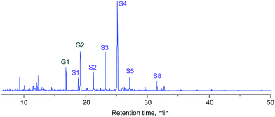 | ||
| Fig. 7 TICs of the hexane extract of lignin oil from the lignin-first biorefinery using 5% Ru/SiC. The structures of the compounds can be found in Fig. 4. | ||
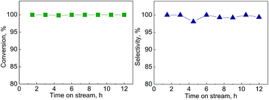 | ||
| Fig. 8 Conversion of bio-oil obtained from lignin depolymerization over MoO3 catalyst and HC selectivity. | ||
The HDO products identified by GC/MS are shown in Fig. 9. The product mainly contained C7–C12 aromatic hydrocarbons, which are quite suitable for jet fuel blends. Such aromatic hydrocarbons were thus blended with jet fuel derived from waste cooking oil and tested according to ASTM 7566 specifications. The test results are summarized in Table 7. The results indicated that the blended sample met the ASTM standards, especially with respect to the density value where jet biofuels always failed due to their iso-paraffin nature. The density value here was 0.805, which fully satisfies the jet fuel requirement.
| Specification test | Special requirement | HFEA | Sample value |
|---|---|---|---|
| Total acid number | ≤0.015 | 0 | 0 |
| Aromatics volume | ≤25 | 0 | 13.7 |
| Olefins | ≤5 | 0 | 0.7 |
| Heat of combustion, MJ kg−1 | ≥42.8 | 44.2 | 43.7 |
| Hydrogen content, wt% | ≥13.4 | 13.6 | 13.4 |
| Thermal stability@260 °C | |||
| Tube deposit rating | ≤3 | 1 | 1 |
| Change in pressure, mm Hg | ≤25 | 0 | 0 |
| Flash point, °C | ≥38 | 41.0 | 47.6 |
| Freeze point, °C | ≤−47 | −58 | −53 |
| Density, kg L−1@15 °C | 0.775–0.840 | 0.748 | 0.805 |
| Viscosity@−40 °C, cSt | ≤12 | 4.0 | 5.2 |
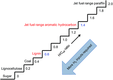
Effective hydrogen-to-carbon ratio (H/Ceff), defined by (H–2O)/C, is usually employed to describe whether a feedstock can be easily converted to hydrocarbons.66 As shown in Fig. 10, the gap of H/Ceff between lignocellulose (0.2) and jet fuel range paraffin (2.0) was as large as 1.8, indicating that a huge amount of H2 input was required. However, the feedstock/product pair of lignin/jet fuel range aromatic hydrocarbon seemed to be the best choice because of the small H/Ceff gap (0.6 vs. 1.4). This indicated that the conversion of lignin to jet fuel range aromatic hydrocarbons could be realized more readily.
3.3. Production of RPF with dimer/oligomer-rich phase
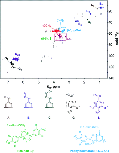
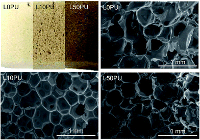
2D HSQC NMR was employed to understand the functional group information of the residue from hexane extraction. As shown in Fig. 11, some typical phenolic dimers/oligomers containing β-5, β–β, and α-O-4 bonds are found. Those dimers/oligomers are insensitive to the above-mentioned hydrogenolysis for monomer production because of the stability of β-5 and β–β bonds and thus unsuitable for jet fuel production. However, the signals of –OCH3 and γOH are very obvious. Quantification of the –OH content by an acetylation method using 1H-NMR analysis demonstrates a high –OH content of 8.0 mmol g−1, implying the high potential of the hexane residue in replacement of polyols, which is one of the materials for polymer preparation. Hence, production of RPF with partial replacement of polyols by different mass fractions of hexane residue was tested.Two different RPF samples with variable polyol replacement percentages were synthesized and characterized in detail. As shown in Fig. 12, the introduction of lignin oil (hexane residue) in RPF resulted in an appropriate foam structure with a slight change in color. The color became deeper as the lignin oil percentage increased. The SEM images show the typical RPF structure for all cases, indicating the successful replacement of polyol by lignin oil in RPF preparation. The successful incorporation of lignin oil in RPF was also demonstrated by FTIR and TG analysis, as shown in the ESI.†
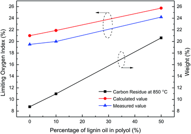
The introduction of lignin oil also led to a slight change in the physical and chemical properties of the RPF. As listed in Table 8, the density of reference RPF (L0PU) was approximately 73.0 kg m−3 and L10PU density, similar to that of the reference one, was 72.6 kg m−3. This probably occurred because addition of 10 wt% of hexane residue had good compatibility with the polyols. The water absorption of L10PU after 24 h water exposure at room temperature reached 36.7 wt%, which is slightly higher than that of the reference one (32.8 wt%). The compressive strength of L10PU was also higher than the reference one. This was mainly attributed to the rigidity of aromatic structures in the hexane residue and the high functionality of –OH, which introduced more crosslinking to the RPF network. The limiting oxygen index (LOI) refers to the minimum oxygen concentration required in the mixture of oxygen and nitrogen to maintain the combustion state under the prescribed experimental conditions. Generally, it is defined that the materials with LOIs less than 22, between 22 and 27, and larger than 27 are flammable, combustible, and flame-retardant materials, respectively.67 As shown in Fig. 13, the LOI of L10PU (20.5) was similar to that of the reference RPF (19.8), both being flammable materials.
| Sample | Density (kg m−3) | Water absorption (wt%) | Compression strength at 10% displacement (kPa) |
|---|---|---|---|
| L0PU | 73.0 | 32.8 | 253 |
| L10PU | 72.6 | 36.7 | 270 |
| L50PU | 73.4 | 22.6 | 156 |
Physical properties of the L50PU showed that further increase in hexane residue content resulted in a stable density of RPF. However, the water absorption and compression strength of L50PU were significantly smaller than those of L10PU, probably caused by the repolymerization of the excess hexane residue, leading to internal defects in RPF. Compared with L10PU, a meaningful change in the properties of L50PU arose from the LOI, which increased from 21.9 to 25.6. The L50PU thus was a combustible material. This fact suggested that the LOI of RPF is significantly influenced by the addition of hexane residue.
Based on the characterization results of the RPFs, the green synthesis of RPF with lignin oil fraction is successfully proved. Partial replacement of polyols by the lignin oil fraction for RPF production not only maintains the uniform cell structure and density of RPF but also improve its water resistance and flame resistance. It is thus a promising method to effectively utilize lignin oil fraction, especially those dimers/oligomers which are difficult to be further converted in downstream applications.
Actually, preparation of RPF with lignin or lignin depolymerized product has been reported by other groups.68,69 However, it is difficult to directly compare the results, because different methods for lignin depolymerization as well as RPF preparation are employed. Our result, at least, proves the applicability of the lignin oil (particularly phenolic dimers/oligomers) from the novel lignin-first biorefinery in RPF production. Such fractions of lignin oil also have a high potential in the preparation of other polymers because of the abundance of methoxy and hydroxyl groups.
3.4. Overview of the lignin-first biorefinery
Based on the above discussion, unit processes with specific advantages in the lignin-first biorefinery are successfully demonstrated. These technologies, after integrating the bio-chemical or chemo-catalytic conversion of the carbohydrate pulp, can built a unique biorefinery system, as proposed in the Introduction section. Fig. S7 in the ESI† shows the biorefinery system with a rough mass distribution. Such a biorefinery system successfully resolves the following key challenges of the lignin-first biorefinery.(1) Catalyst regeneration. The proposed Ru/SiC catalyst used in the lignin-first biorefinery can be easily regenerated by calcination, which is a prevalent method in present chemical industries. The recyclable properties of the catalyst enable the lignin-first biorefinery to be feasible for large-scale use.
(2) Product diversification. In the lignin-first biorefinery, one major interesting feature is the preservation of C9 basic structure during the processing. Other benefits are also reported such as the high degree preservation of hydroxyl groups. Our results further confirm the hexane extracted phase of lignin oil is effectively converted into aromatic hydrocarbons under ambient pressure to be suitable as jet fuel blends. Considering the small H/Ceff gap between the lignin and aromatics and the preservation of C9 aromatic structures, the lignin-first biorefinery is considered as the most effective and straight forward pathway for conversion of lignocellulosic biomass into jet biofuel with minimum hydrogen input and chemical changes. The residue from hexane extraction, which is rich in methoxy and hydroxyl groups, is also proved to be suitable for RPF production with even better water and flame resistance. The products from the lignin-first biorefinery are thus diversified in both fuels and chemicals.
4. Conclusions
The following conclusions can be drawn based on the works presented in this paper:(1) SiC is an effective and regenerable support in the lignin-first biorefinery. The catalytic performance of Ru/SiC is even better than the state-of-the-art results from Ru/C under identical conditions, and it remains stable after two recycling runs with the regenerated catalyst by calcination.
(2) 50 wt% of lignin oil produced from the lignin-first biorefinery can be extracted by hexane, which was found to be a very promising solvent for the conversion of phenols over MoO3 catalyst under ambient pressure. 6.9 wt%-dry-apple-wood of jet fuel range aromatic hydrocarbons, which can be used as a blend for jet biofuels, was obtained from the ambient pressure HDO of the hexane extract over MoO3.
(3) Partial replacement of polyols by the hexane residue up to 50 wt% for RPF production not only maintains the uniform cell structure and density of RPF but also improves its water resistance and flame resistance.
Conflicts of interest
There are no conflicts to declare.Acknowledgements
This work was supported by the National Natural Science Foundation of China (Grant No. U1663227).References
- C. Xu, R. A. D. Arancon, J. Labidi and R. Luque, Chem. Soc. Rev., 2014, 43, 7485–7500 RSC.
- W.-J. Liu, H. Jiang and H.-Q. Yu, Green Chem., 2015, 17, 4888–4907 RSC.
- Q. Kang, L. Appels, T. Tan and R. Dewil, Sci. World J., 2014, 2014, 1–13 Search PubMed.
- J. Baeyens, Q. Kang, L. Appels, R. Dewil, Y. Lv and T. Tan, Prog. Energy Combust. Sci., 2015, 47, 60–88 CrossRef.
- S. K. Hanson, R. Wu and L. A. P. Silks, Angew. Chem., Int. Ed., 2012, 51, 3410–3413 CrossRef CAS PubMed.
- C. S. Lancefield, O. S. Ojo, F. Tran and N. J. Westwood, Angew. Chem., Int. Ed., 2015, 54, 258–262 CrossRef CAS PubMed.
- R. Ma, W. Hao, X. Ma, Y. Tian and Y. Li, Angew. Chem., Int. Ed., 2014, 53, 7310–7315 CrossRef CAS PubMed.
- X. Wang and R. Rinaldi, Angew. Chem., Int. Ed., 2013, 52, 11499–11503 CrossRef CAS PubMed.
- D. R. Vardon, M. A. Franden, C. W. Johnson, E. M. Karp, M. T. Guarnieri, J. G. Linger, M. J. Salm, T. J. Strathmann and G. T. Beckham, Energy Environ. Sci., 2015, 8, 617–628 CAS.
- Q. Song, F. Wang, J. Cai, Y. Wang, J. Zhang, W. Yu and J. Xu, Energy Environ. Sci., 2013, 6, 994–1007 CAS.
- J. S. Luterbacher, A. Azarpira, A. H. Motagamwala, F. Lu, J. Ralph and J. A. Dumesic, Energy Environ. Sci., 2015, 8, 2657–2663 CAS.
- A. J. Ragauskas, G. T. Beckham, M. J. Biddy, R. Chandra, F. Chen, M. F. Davis, B. H. Davison, R. A. Dixon, P. Gilna, M. Keller, P. Langan, A. K. Naskar, J. N. Saddler, T. J. Tschaplinski, G. A. Tuskan and C. E. Wyman, Science, 2014, 344, 1246843 CrossRef PubMed.
- J. Zakzeski, P. C. A. Bruijnincx, A. L. Jongerius and B. M. Weckhuysen, Chem. Rev., 2010, 110, 3552–3599 CrossRef CAS PubMed.
- C. Li, X. Zhao, A. Wang, G. W. Huber and T. Zhang, Chem. Rev., 2015, 115, 11559–11624 CrossRef CAS PubMed.
- A. Rahimi, A. Ulbrich, J. J. Coon and S. S. Stahl, Nature, 2014, 515, 249–252 CrossRef CAS PubMed.
- W. Yan, T. C. Acharjee, C. J. Coronella and V. R. Vásquez, Environ. Prog. Sustainable Energy, 2009, 28, 435–440 CrossRef CAS.
- M. O. S. Dias, M. P. da Cunha, R. Maciel Filho, A. Bonomi, C. D. F. Jesus and C. E. V. Rossell, J. Ind. Microbiol. Biotechnol., 2011, 38, 955–966 CrossRef CAS PubMed.
- G. Banerjee, S. Car, J. S. Scott-Craig, D. B. Hodge and J. D. Walton, Biotechnol. Biofuels, 2011, 4, 16 CrossRef CAS PubMed.
- M. J. Bussemaker and D. Zhang, Ind. Eng. Chem. Res., 2013, 52, 3563–3580 CrossRef CAS.
- H. Ma, W.-W. Liu, X. Chen, Y.-J. Wu and Z.-L. Yu, Bioresour. Technol., 2009, 100, 1279–1284 CrossRef CAS PubMed.
- J. S. Luterbacher, J. M. Rand, D. M. Alonso, J. Han, J. T. Youngquist, C. T. Maravelias, B. F. Pfleger and J. A. Dumesic, Science, 2014, 343, 277–280 CrossRef CAS PubMed.
- T. Renders, S. Van den Bosch, S. F. Koelewijn, W. Schutyser and B. F. Sels, Energy Environ. Sci., 2017, 10, 1551–1557 CAS.
- A. V. Bridgwater and M. L. Cottam, Energy Fuels, 1992, 6, 113–120 CrossRef CAS.
- R. Weingarten, W. C. Conner and G. W. Huber, Energy Environ. Sci., 2012, 5, 7559–7574 CAS.
- P. Ferrini and R. Rinaldi, Angew. Chem., Int. Ed., 2014, 53, 8634–8639 CrossRef CAS PubMed.
- T. Parsell, S. Yohe, J. Degenstein, T. Jarrell, I. Klein, E. Gencer, B. Hewetson, M. Hurt, J. I. Kim, H. Choudhari, B. Saha, R. Meilan, N. Mosier, F. Ribeiro, W. N. Delgass, C. Chapple, H. I. Kenttamaa, R. Agrawal and M. M. Abu-Omar, Green Chem., 2015, 17, 1492–1499 RSC.
- S. Van den Bosch, W. Schutyser, R. Vanholme, T. Driessen, S. F. Koelewijn, T. Renders, B. De Meester, W. J. J. Huijgen, W. Dehaen, C. M. Courtin, B. Lagrain, W. Boerjan and B. F. Sels, Energy Environ. Sci., 2015, 8, 1748–1763 CAS.
- D. E. Resasco and S. Crossley, AIChE J., 2009, 55, 1082–1089 CrossRef CAS.
- J. N. Mwangi, N. Wang, A. Ritts, J. L. Kunz, C. G. Ingersoll, H. Li and B. Deng, Environ. Toxicol. Chem., 2011, 30, 981–987 CrossRef CAS PubMed.
- Z. Liu, W. Shen, W. Bu, H. Chen, Z. Hua, L. Zhang, L. Li, J. Shi and S. Tan, Microporous Mesoporous Mater., 2005, 82, 137–145 CrossRef CAS.
- C. Hoffmann, P. Plate, A. Steinbruck and S. Kaskel, Catal. Sci. Technol., 2015, 5, 4174–4183 CAS.
- J. L. Graham, R. C. Striebich, K. J. Myers, D. K. Minus and W. E. Harrison, Energy Fuels, 2006, 20, 759–765 CrossRef CAS.
- J. Q. Bond, A. A. Upadhye, H. Olcay, G. A. Tompsett, J. Jae, R. Xing, D. M. Alonso, D. Wang, T. Zhang, R. Kumar, A. Foster, S. M. Sen, C. T. Maravelias, R. Malina, S. R. H. Barrett, R. Lobo, C. E. Wyman, J. A. Dumesic and G. W. Huber, Energy Environ. Sci., 2014, 7, 1500–1523 CAS.
- M. Saidi, F. Samimi, D. Karimipourfard, T. Nimmanwudipong, B. C. Gates and M. R. Rahimpour, Energy Environ. Sci., 2014, 7, 103–129 CAS.
- S. De, B. Saha and R. Luque, Bioresour. Technol., 2015, 178, 108–118 CrossRef CAS PubMed.
- C. R. Lee, J. S. Yoon, Y.-W. Suh, J.-W. Choi, J.-M. Ha, D. J. Suh and Y.-K. Park, Catal. Commun., 2012, 17, 54–58 CrossRef CAS.
- D.-Y. Hong, S. J. Miller, P. K. Agrawal and C. W. Jones, Chem. Commun., 2010, 46, 1038–1040 RSC.
- H. Ohta, H. Kobayashi, K. Hara and A. Fukuoka, Chem. Commun., 2011, 47, 12209–12211 RSC.
- T. G. Kelly and J. G. Chen, Green Chem., 2014, 16, 777–784 RSC.
- J.-S. Moon, E.-G. Kim and Y.-K. Lee, J. Catal., 2014, 311, 144–152 CrossRef CAS.
- M. Shetty, K. Murugappan, T. Prasomsri, W. H. Green and Y. Román-Leshkov, J. Catal., 2015, 331, 86–97 CrossRef CAS.
- T. Prasomsri, T. Nimmanwudipong and Y. Roman-Leshkov, Energy Environ. Sci., 2013, 6, 1732–1738 CAS.
- T. Prasomsri, M. Shetty, K. Murugappan and Y. Roman-Leshkov, Energy Environ. Sci., 2014, 7, 2660–2669 CAS.
- Y. H. Hu, Y. Gao, D. N. Wang, C. P. Hu, S. Zu, L. Vanoverloop and D. Randall, J. Appl. Polym. Sci., 2002, 84, 591–597 CrossRef CAS.
- J. O. Akindoyo, M. D. H. Beg, S. Ghazali, M. R. Islam, N. Jeyaratnam and A. R. Yuvaraj, RSC Adv., 2016, 6, 114453–114482 RSC.
- S. Hu, X. Luo and Y. Li, ChemSusChem, 2014, 7, 66–72 CrossRef CAS PubMed.
- Y.-J. Hao, G.-Q. Jin, X.-D. Han and X.-Y. Guo, Mater. Lett., 2006, 60, 1334–1337 CrossRef CAS.
- X. Han, S. Zheng, Y. Zhang, K. Zheng, S. Zhang, Z. Zhang, X. Zhang, X. Liu, G. Chen, Y. Hao and X. Guo, Nano Lett., 2008, 8, 2258–2264 CrossRef CAS PubMed.
- J. J. Niu and J. N. Wang, Acta Mater., 2009, 57, 3084–3090 CrossRef CAS.
- X. Tong, L. Dong, G. Jin, Y. Wang and X. Y. Guo, Fuel Cells, 2011, 11, 907–910 CrossRef CAS.
- A. Romero, D. A. Cantero, A. Nieto-Marquez, C. Martinez, E. Alonso and M. J. Cocero, Green Chem., 2016, 18, 4051–4062 RSC.
- A. S. Aricò, Z. Poltarzewski, H. Kim, A. Morana, N. Giordano and V. Antonucci, J. Power Sources, 1995, 55, 159–166 CrossRef.
- L.-P. Xiao, S. Wang, H. Li, Z. Li, Z.-J. Shi, L. Xiao, R.-C. Sun, Y. Fang and G. Song, ACS Catal., 2017, 7, 7535–7542 CrossRef CAS.
- W. Schutyser, S. Van den Bosch, T. Renders, T. De Boe, S. F. Koelewijn, A. Dewaele, T. Ennaert, O. Verkinderen, B. Goderis, C. M. Courtin and B. F. Sels, Green Chem., 2015, 17, 5035–5045 RSC.
- T. Renders, W. Schutyser, S. Van den Bosch, S.-F. Koelewijn, T. Vangeel, C. M. Courtin and B. F. Sels, ACS Catal., 2016, 6, 2055–2066 CrossRef CAS.
- S. Van den Bosch, T. Renders, S. Kennis, S. F. Koelewijn, G. Van den Bossche, T. Vangeel, A. Deneyer, D. Depuydt, C. M. Courtin, J. M. Thevelein, W. Schutyser and B. F. Sels, Green Chem., 2017, 19, 3313–3326 RSC.
- E. A. Paoli, F. Masini, R. Frydendal, D. Deiana, C. Schlaup, M. Malizia, T. W. Hansen, S. Horch, I. E. L. Stephens and I. Chorkendorff, Chem. Sci., 2015, 6, 190–196 RSC.
- J. Okal and M. Zawadzki, Appl. Catal., B, 2009, 89, 22–32 CrossRef CAS.
- C.-C. Chang, S. K. Green, C. L. Williams, P. J. Dauenhauer and W. Fan, Green Chem., 2014, 16, 585–588 RSC.
- M. A. Mellmer, C. Sener, J. M. R. Gallo, J. S. Luterbacher, D. M. Alonso and J. A. Dumesic, Angew. Chem., Int. Ed., 2014, 53, 11872–11875 CrossRef CAS PubMed.
- C. H. Christensen, I. Schmidt, A. Carlsson, K. Johannsen and K. Herbst, J. Am. Chem. Soc., 2005, 127, 8098–8102 CrossRef CAS PubMed.
- F. de Miguel Mercader, M. J. Groeneveld, S. R. A. Kersten, N. W. J. Way, C. J. Schaverien and J. A. Hogendoorn, Appl. Catal., B, 2010, 96, 57–66 CrossRef CAS.
- A. Benadda, A. Katrib and A. Barama, Appl. Catal., A, 2003, 251, 93–105 CrossRef CAS.
- A. Katrib, A. Benadda, J. W. Sobczak and G. Maire, Appl. Catal., A, 2003, 242, 31–40 CrossRef CAS.
- X. Dupain, R. A. Krul, C. J. Schaverien, M. Makkee and J. A. Moulijn, Appl. Catal., B, 2006, 63, 277–295 CrossRef CAS.
- H. Zhang, Y.-T. Cheng, T. P. Vispute, R. Xiao and G. W. Huber, Energy Environ. Sci., 2011, 4, 2297–2307 CAS.
- M. Suzanne, M. A. Delichatsios and J. P. Zhang, Combust. Flame, 2014, 161, 288–294 CrossRef CAS.
- N. Mahmood, Z. Yuan, J. Schmidt and C. Xu, Renewable Sustainable Energy Rev., 2016, 60, 317–329 CrossRef CAS.
- C. S. Carriço, T. Fraga and V. M. D. Pasa, Eur. Polym. J., 2016, 85, 53–61 CrossRef.
Footnotes |
| † Electronic supplementary information (ESI) available. See DOI: 10.1039/c7se00535k |
| ‡ Equal contribution to this work. |
| This journal is © The Royal Society of Chemistry 2018 |

