Influence of additives in a PVDF-based solid polymer electrolyte on conductivity and Li-ion battery performance
Furi
Wang
,
Libo
Li
 *,
Xueying
Yang
,
Jun
You
*,
Yanping
Xu
,
Heng
Wang
,
Yue
Ma
and
Guanxiong
Gao
*,
Xueying
Yang
,
Jun
You
*,
Yanping
Xu
,
Heng
Wang
,
Yue
Ma
and
Guanxiong
Gao
College of Chemical and Environmental Engineering, Harbin University of Science and Technology, No. 4 Lin Yuan Road, Harbin 150040, People’s Republic of China. E-mail: llbo2002@126.com; Fax: +86-451-86392708; Tel: +86-451-86392713
First published on 11th December 2017
Abstract
Polyvinylidene fluoride (PVDF) was used as a membrane matrix, and then many groups of experiments with different additives were carried out to investigate the factor that affects conductivity of the solid polymer electrolyte (SPE). Impedance measurements were performed using an electrochemical work station. Data obtained through alternating current (AC) impedance measurements revealed that the conductivity of the blending membrane was improved. The presence of hydroxyl end-groups and some electron-donating groups in the additives was helpful for increasing the conductivity. In particular, when PVP and EDTA were added, the conductivity of the polymer electrolyte could achieve a value of 7.19 × 10⁻⁴ S cm−1 at 25 °C and a lithium ion transference number of 0.49. The electrochemical stability window was about 4.3 V (vs. Li+/Li).
Introduction
Nowadays, lithium ion batteries (LIBs) are widely used within our lives. However, liquid electrolyte has some disadvantages such as instability, inflammability, safety issues, and so on. Therefore, solid polymer electrolyte (SPE) has been a popular research subject in recent years. M. M. Rao et al. prepared a PE-supported P(AN-co-MMA) membrane with an ionic conductivity of 1.22 × 10⁻³ S cm−1 at 25 °C.1 Xueyi et al. reported polymer electrolytes composed of (methyl methacrylate-butyl acrylate-acrylonitrile-styrene) (P(MMA-BA-AN-St)/PE) in a copolymerization-modification with an ionic conductivity of 2.7 × 10⁻³ S cm−1.2 M. C. Borghini obtained a (PEG) 2000/(PEGDME) 500 electrolyte membrane with a conductivity of ∼1.0 × 10⁻⁴ S cm−1 at 25 °C.3Polyvinylidene fluoride (PVDF) is used as the membrane matrix due to its outstanding mechanical properties, good thermal stability and chemical properties. Nevertheless, there still exists a problem waiting to be solved, which is the low ionic conductivity of the polymer electrolytes compared to the liquid electrolyte solutions at room temperature. The ionic conductive ability in the solid polymer electrolyte mainly depends on the functional group of the polymer chain which decides the ion channel, the crystallinity, the chemical potential gradient and the electric field gradient. Two ideas can be considered in order to decrease crystallinity: one is to raise the salt content of the electrolyte to raise the complex reaction degree; the other is to reduce the complex crystalline phase. Sheng Bi et al. reported a blend of PEO and PVDF to reduce their crystallinity.4
There have been many methods to modify the polymer electrolyte, for example blending, copolymerization, cross-linking and the addition of nano-particles.5–10 Meanwhile, blending and adding additives are the most simple and effective ways to improve the electrochemical performance and mechanical properties of an electrolyte membrane. In terms of the performance of the battery, the additive can (1) promote the formation of a solid electrolyte interface (SEI) film; (2) reduce irreversible capacity and enhance cycle performance; (3) improve the stability of the lithium; (4) protect the cathode material from decomposition or overload; (5) improve the performance of the electrolyte (conductivity, viscosity, mechanical performance, and so on.).11–15 G. Q. Zhang et al. prepared a nano-SiO2(CaCO3) filled P(VDF-HFP)/PMMA membrane with an ionic conductivity of 3.42 × 10⁻⁴ S cm−1.16
The main objective in this work was to research the effects of additive dosage and category of PVDF-based polymer matrix on the conductivity of a solid polymer electrolyte membrane. A blending modification was used to destroy the structure of PVDF in order to introduce functional branched groups into the main chains of the polymer matrix to improve the conductivity of the polymer electrolyte.
Experimental
Preparation of the membrane
Before being used polyvinylidene fluoride (PVDF), polyvinylpyrrolidone (PVP), and ethylene diamine tetraacetic acid (EDTA) were put in a drying oven for 1 hour. Considering the property of high moisture sensitivity of lithium bis(trifluoromethanesulfonyl)imide (LiTFSI), LiTFSI was contained in a glass jar and desiccant was also put in the jar in order to control the humidity of the jar. Before being used, LiTFSI was dried under vacuum at 80 °C for 24 h. Then, PVDF was dissolved in N,N-dimethylformamide (DMF), meanwhile EDTA was dispersed in DMF. Both were stirred for 12 hours before being mixed together, and then PVP was added into the above mixed solution and stirred for 12 hours. LiTFSI was added into the above mixture and stirred for 6 hours. Finally, the mixture was cast on clean glass, and put into a vacuum oven for 1 hour at 120 °C and the semi-transparent and resilient membrane was obtained.Characterization of the membranes
Scanning electron microscopy (SEM, JSM-6480A, JEOL) images of the polymer membrane were taken to investigate the surface morphology. To optimize the result, the as-prepared membranes were coated with a layer of gold powder. XRD studies were performed using an X′pert PROPANalytical diffractometer.The impedance measurements were performed using a CHI760E electrochemical work station and the conductivity (σ) was evaluated through the high frequency of the AC impedance method using the following equation:1,17
| σ = d/(RbS) | (1) |
To test the Li+ transference number (tLi+) of the electrolytes, the LIR2025 coin-type cells were assembled in an Ar-filled dry glove box by sandwiching a 16 mm diameter electrolyte membrane between two Li slices. The transference number was evaluated using the following equation:17
| tLi+ = Iss(ΔV − RoIo)/Io(ΔV − RssIss) | (2) |
The electrochemical window was tested by linear sweep voltammetry (LSV). Cyclic voltammetry (CV) was used to test the compatibility of the membrane and the electrode by a coin-type Li/SPE/LiFePO4 cell with a scanning rate of 0.1 mV s−1 at a voltage range of 2.5–4.2 V, and charge/discharge tests were performed on the LAND system.
DSC was performed on a Pyris Diamond DSC instrument (PerkinElmer Co., Ltd.) under N2 atmosphere. The measurements were carried out from 40 °C to 400 °C at a heating rate of 10 °C min−1.
Results and discussion
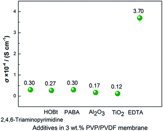
Conductivity values of 8 groups of experiments of different additives with electron-donating groups in the PVDF matrix are shown in Fig. 1. In terms of PVP/PVDF, the electrolyte membrane with 3 wt% PVP displays an ionic conductivity of 1.15 × 10⁻⁴ S cm−1, which is a higher value than the other additives, including Al2O3, TiO2, hydroxybenzotriazole (HOBt), 2,4,6-triaminopyrimidine, 4-aminobenzoic acid (PABA), and ethylene diamine tetraacetic acid (EDTA).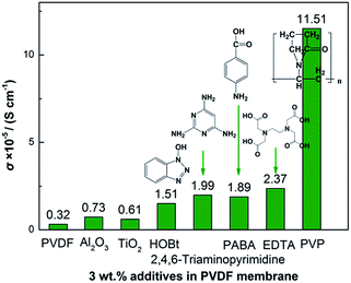 | ||
| Fig. 1 Influence of the additives with electron-donating groups on the conductivity of the PVDF membrane. | ||
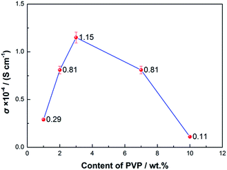
In order to determine the optimum content of PVP, different amounts of PVP were added into the PVDF matrix. From Fig. 2, it is seen that the PVDF membrane with 3 wt% PVP has a higher conductivity of 1.15 × 10⁻⁴ S cm−1. The lone pairs of electrons of the N elements in PVP, which are uniformly distributed at intervals in the PVDF matrix due to its moderate content (3 wt%), will attract Li+ at the same time as one polaron will help Li+ dissociate from TFSI− and be transferred.
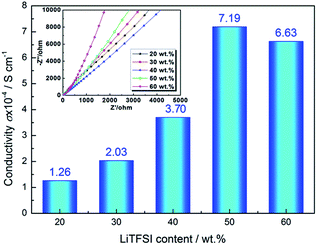
To further improve the conductivity, other additives are chosen to add into the PVP/PVDF membrane. In Fig. 3, the 2 wt% EDTA/3 wt% PVP/PVDF electrolyte membrane has the highest conductivity. The conductivity of the EDTA/PVP/PVDF membrane with different amounts of LiTFSI was tested. Fig. 4 shows the Nyquist plots of the EDTA/PVP/PVDF membrane with different amounts of LiTFSI. It was found that the membrane with 50% LiTFSI exhibits the highest conductivity, even more than the membrane with 60% LiTFSI. This may be caused by the precipitation of LiTFSI on the surface of the membrane with 60% LiTFSI. The conductivity of the EDTA/PVP/PVDF membrane with 50% LiTFSI could achieve 7.19 × 10⁻⁴ S cm−1 at 25 °C.
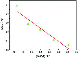
Fig. 5 shows the Arrhenius curve of the EDTA/PVP/PVDF membrane. The linearity of the plot indicates that ionic movement of the electrolyte membrane is deeply related to temperature. The activation energy of conductivity is 13.70 kJ mol−1, which is lower than lots of membranes reported.18,19 So, it is easier for Li+ to pass through the membrane and that may give rise to a higher ionic conductivity. It can be observed that the ionic conductivity of the prepared EDTA/PVP/PVDF membrane increases as the temperature increases.20–22 As a result of the existence of C–F and C–H bonds in PVDF, entanglement and hydrogen bond effects always occur in PVDF. Due to similar atomic radii of hydrogen and fluorine atoms, PVDF exists in various structures.23 The α-phase PVDF with a Trans-Gauche-Trans-Gauche (TGTG) chain conformation is the most common structure, while β-phase PVDF with a Trans–Trans (TT) chain conformation shows higher polar properties than α-phase PVDF.24 Fluorine in β-phase PVDF is equivalent, whereas fluorine is non-equivalent in α-phase PVDF. In α-polymorph (TGTG), F has a close distance to H, thus this structure makes PVDF hard to interact with other molecules except itself. Crystallinity in α-polymorph PVDF is high, so it is hard for Li+ to be transferred into it. The strong interaction between the carbonyl group (C![[double bond, length as m-dash]](https://www.rsc.org/images/entities/char_e001.gif) O) in PVP and the fluorine group (C–F2) in PVDF gives rise to a β-phase characteristic of PVDF, which shows higher polar properties that help Li+ to dissociate.25 The structure of the carbonyl groups (C
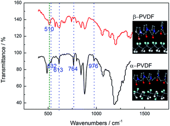
O) in PVP and the fluorine group (C–F2) in PVDF gives rise to a β-phase characteristic of PVDF, which shows higher polar properties that help Li+ to dissociate.25 The structure of the carbonyl groups (C![[double bond, length as m-dash]](https://www.rsc.org/images/entities/char_e001.gif) O) in PVP and EDTA means that (C–F2) bonds in PVDF tend to be distributed in one side of the chain, while C–H bonds tend to be distributed in the other side.26 The transformation of PVDF from α-phase to β-phase makes PVDF more polar and decreases the crystallinity of PVDF. Fig. 6 shows the FT-IR spectra of the β-phase and α-phase of PVDF. The characteristic IR peaks at 532 cm−1, 613 cm−1, 764 cm−1 and 976 cm−1 are all visible in the α-form, and an IR peak at 510 cm−1 is visible in β-form PVDF.27–29 The difference in the FT-IR spectra represents the transformation of PVDF from α-phase to β-phase caused by the interaction between the carbonyl group (C
O) in PVP and EDTA means that (C–F2) bonds in PVDF tend to be distributed in one side of the chain, while C–H bonds tend to be distributed in the other side.26 The transformation of PVDF from α-phase to β-phase makes PVDF more polar and decreases the crystallinity of PVDF. Fig. 6 shows the FT-IR spectra of the β-phase and α-phase of PVDF. The characteristic IR peaks at 532 cm−1, 613 cm−1, 764 cm−1 and 976 cm−1 are all visible in the α-form, and an IR peak at 510 cm−1 is visible in β-form PVDF.27–29 The difference in the FT-IR spectra represents the transformation of PVDF from α-phase to β-phase caused by the interaction between the carbonyl group (C![[double bond, length as m-dash]](https://www.rsc.org/images/entities/char_e001.gif) O) of PVP and the fluorine group (C–F2) of PVDF. The spectra also assure the molecular model which exhibits this transformation process. The mixing of PVDF and PVP weakens the entanglement and hydrogen bond effects in PVDF and decreases the crystallinity of PVDF.
O) of PVP and the fluorine group (C–F2) of PVDF. The spectra also assure the molecular model which exhibits this transformation process. The mixing of PVDF and PVP weakens the entanglement and hydrogen bond effects in PVDF and decreases the crystallinity of PVDF.
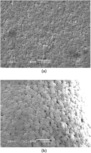
Fig. 7 shows SEM images of the EDTA/PVP/PVDF membrane microstructures. Due to the interaction between the carbonyl group (C![[double bond, length as m-dash]](https://www.rsc.org/images/entities/char_e001.gif) O) of PVP and the fluorine group (C–F2) of PVDF, PVP is used as a pore-forming agent.30–32
O) of PVP and the fluorine group (C–F2) of PVDF, PVP is used as a pore-forming agent.30–32
Pores with uniform sizes can be seen and the porous structure provides tunnels for Li+ to pass.
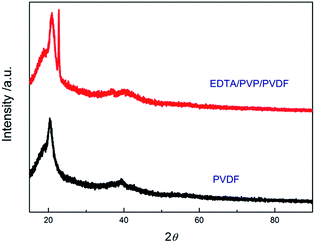
XRD patterns of the PVDF and EDTA/PVP/PVDF membranes are shown in Fig. 8. The XRD patterns can be divided into two areas which are the area under the crystalline peaks and the area of the broad halo. These two areas can be considered as degrees of crystallinity and amorphicity, respectively. Then the ratio of the degree of crystallinity can be estimated using the following equation:33
| χc (%) = (S/So) × 100% | (3) |
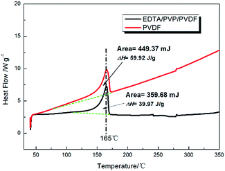
The DSC thermograms of the PVDF and EDTA/PVP/PVDF membranes are shown in Fig. 9. Both of the membranes show an endothermic peak at a temperature of 165 °C, which may be attributed to the melting point of the PVDF polymer electrolyte. ΔHm of the PVDF and EDTA/PVP/PVDF membranes is estimated to be 59.92 J g−1 and 39.97 J g−1, respectively. Then, the degree of crystallinity (χc) is calculated according to following equation:33
| χc (%) = (ΔHm/ΔH0m)(1/Wf) | (4) |
χ c of the PVDF and EDTA/PVP/PVDF membranes is calculated to be 58.34% and 40.53%, respectively. The decline of χc is due to the transformation process of PVDF from α-phase to β-phase which makes PVDF more polar and weakens entanglement and hydrogen bond effects in PVDF.
The lithium ion transference number (tLi+) is calculated according to eqn (2). Fig. 10 shows the impedance behaviour of the EDTA/PVP/PVDF polymer electrolyte membrane at room temperature. From the point of ion transference, the polymer electrolytes can be divided into organic polymer, organic–inorganic hybrid polymer and anion acceptor. For the organic polymer discussed in this paper, anions are bonded onto a chain of the polymer electrolytes easily due to the one-sided C–H bonds of β-phase PVDF.
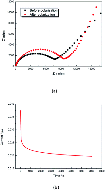 | ||
| Fig. 10 Electrochemical impedance spectroscopy before and after polarization (a) and I–t curves during the polarization process (b). | ||
Anions of LiTFSI are absorbed onto chains of PVDF, thus the cation transference number is enhanced. Fig. 10a shows the electrode/electrolyte interfacial resistance Ro and the electrode/electrolyte interfacial resistance Rss after polarization. The initial polarization current Io (3.88 × 10⁻⁵ mA) and the steady state current Iss (1.95 × 10⁻⁵ mA) are obtained from Fig. 10b. The Li ion transference number (tLi+) is calculated to be 0.49.
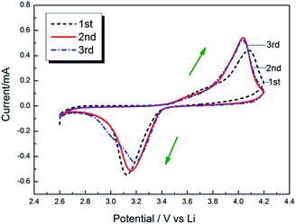
The electrochemical stability window (ESW) is an important parameter of the electrolyte. Linear sweep voltammetry (LSV) is employed to measure the electrochemical stability of polymer electrolytes using Li/SPE/SS (SS: stainless steel) cells. Fig. 11 shows the linear sweep voltammetry at a scan rate of 2 mV s−1. The EDTA/PVP/PVDF polymer electrolyte membrane shows an anodic stability of about 4.8 V (vs. Li+/Li) and a reduction potential of about 0.5 V (vs. Li+/Li). The electrochemical stability window is about 4.3 V, and 4.3 V totally satisfies the requirement of a safe lithium ion battery. The voltage of intercalation/deintercalation of lithium ions is obtained through the redox peaks in Fig. 12. The first-time cycle shows that 4.1 V corresponds to anodic oxidation, and 3.1 V corresponds to cathodic reduction. In the second and third cycles, the voltages of oxidation and reduction are about 4.0 V and 3.2 V, respectively.
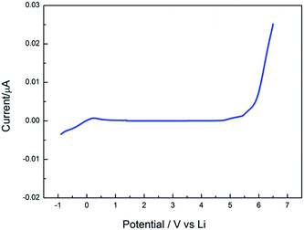 | ||
| Fig. 11 Linear sweep voltammetry curve of the EDTA/PVP/PVDF polymer electrolyte in the Li/SPE/SS cell with a scan rate of 2 mV s−1. | ||
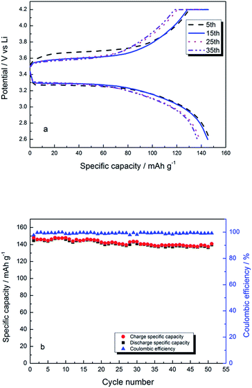
This change in voltage indicates a good compatibility between the EDTA/PVP/PVDF membrane and LiFePO4 electrode. Fig. 13a shows voltage curves vs. specific capacity of Li/SEP/LiFePO4 at 0.1C rate between 2.6 V and 4.2 V at room temperature. The initial charging platform is about 3.55 V and the discharging platform is about 3.35 V. The first and the second discharge cycles show a capacity of 147.9 mA h g−1 and 146.0 mA h g−1, respectively. Fig. 13b shows charge/discharge specific capacity with a cycle number at 1C. The charge and discharge capacity is 140.8 mA h g−1 and 139.7 mA h g−1, respectively, at no. 50 cycle and the coulombic efficiency is about 99%.
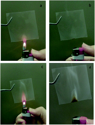
Flammability tests of the EDTA/PVP/PVDF polymer electrolyte membrane were applied. Fig. 14a shows the sample on the outer part of the flame of a lighter for 3 seconds. After removing the flame, the membrane is extinguished right away as shown in Fig. 14b.
Then the sample is put in the flame for about 7 seconds until it starts to burn, as shown in Fig. 14c. The sample is burned for less than 1 second and is less scorched at the bottom, and is then self-extinguished as shown in Fig. 14d. The EDTA/PVP/PVDF polymer electrolyte membrane is self-extinguishable and has a great fire-retardant property, which provides a high safety index.
Conclusions
The EDTA/PVP/PVDF membrane containing high β-phase PVDF has been fabricated through the interaction of the carbonyl group (C![[double bond, length as m-dash]](https://www.rsc.org/images/entities/char_e001.gif) O) of PVP and the fluorine group (C–F2) of PVDF. The existence of the strong interaction gave rise to a higher polar property of PVDF that decreased the crystallinity of PVDF and helped Li+ to dissociate. EDTA in this paper was used as an additive, which has many amino groups and hydroxyl end-groups to help in decreasing the crystallinity of PVDF. The transform process was tested using FT-IR spectra. A porous structure was found in the membrane by the SEM images. The conductivity of the polymer electrolyte could achieve 7.19 × 10⁻⁴ S cm−1 at 25 °C and a lithium ion transference number of 0.49. The electrochemical stability window is about 4.3 V (vs. Li+/Li). Charge/discharge tests were performed on the LAND test system at 1C at room temperature and the coulombic efficiency is about 99%.
O) of PVP and the fluorine group (C–F2) of PVDF. The existence of the strong interaction gave rise to a higher polar property of PVDF that decreased the crystallinity of PVDF and helped Li+ to dissociate. EDTA in this paper was used as an additive, which has many amino groups and hydroxyl end-groups to help in decreasing the crystallinity of PVDF. The transform process was tested using FT-IR spectra. A porous structure was found in the membrane by the SEM images. The conductivity of the polymer electrolyte could achieve 7.19 × 10⁻⁴ S cm−1 at 25 °C and a lithium ion transference number of 0.49. The electrochemical stability window is about 4.3 V (vs. Li+/Li). Charge/discharge tests were performed on the LAND test system at 1C at room temperature and the coulombic efficiency is about 99%.
Conflicts of interest
There are no conflicts to declare.Acknowledgements
This work has been supported financially by the National Natural Science Foundation of China (Grant No. 21506043), Harbin application technology research and development projects [grant number 2015RAQXJ030] and National Natural Science Foundation of China (Grant No. 21706043).Notes and references
- M. M. Rao, J. S. Liu, W. S. Li, Y. Liang and D. Y. Zhou, J. Membr. Sci., 2008, 322, 314–319 CrossRef CAS.
- X. Y. Luo, Y. H. Liao, H. L. Xie, Y. M. Zhu, Q. M. Huang and W. S. Li, Electrochim. Acta, 2016, 220, 47–56 CrossRef CAS.
- M. C. Borghini, M. Mastragostino and A. Zanelli, Electrochim. Acta, 1996, 15, 2369–2373 CrossRef.
- S. Bi, C.-N. Sun, T. A. Zawodzinski, F. Ren, J. K. Keum, S.-K. Ahn, D. Li and J. Chen, J. Polym. Sci., Part B: Polym. Phys., 2015, 53, 1450–1457 CrossRef CAS.
- D. W. Kim, J. K. Park and H. W. Rhee, Solid State Ionics, 1996, 83, 49–56 CrossRef CAS.
- K. K. Kumar, M. Ravi, Y. Pavani, S. Bhavani, A. K. Sharma and V. V. R. Narasimha Rao, J. Membr. Sci., 2014, 454, 200–211 CrossRef CAS.
- M. Nasef, Solid State Ionics, 2004, 171, 243–249 CrossRef CAS.
- R. Baskaran, S. Selvasekarapandian, G. Hirankumar and M. S. Bhuvaneswari, Ionics, 2004, 10, 129–134 CrossRef CAS.
- J. E. Weston and B. C. H. Steele, Solid State Ionics, 1982, 7, 75–79 CrossRef CAS.
- D. Kim, K. Jeon, Y. Lee, J. Seo, K. Seo, H. Han and S. Khan, Prog. Org. Coat., 2012, 74, 435–442 CrossRef CAS.
- R. Wang, X. Li, Z. Wang and H. Zhang, Nano Energy, 2017, 34, 131–140 CrossRef CAS.
- J. H. Kim, S.-Y. Bae, J.-H. Min, S.-W. Song and D.-W. Kim, Electrochim. Acta, 2012, 78, 11–16 CrossRef CAS.
- K. Sato, L. Zhao, S. Okada and J.-I. Yamaki, J. Power Sources, 2011, 196, 5617–5622 CrossRef CAS.
- E. Han, Q. Jing, L. Zhu, G. Zhang and S. Ma, J. Alloys Compd., 2015, 618, 629–634 CrossRef CAS.
- C. Qi, X. Ma, G. Ning, X. Song, B. Chen, X. Lan, Y. Li, X. Zhang and J. Gao, Carbon, 2015, 92, 245–253 CrossRef CAS.
- G. Q. Zhang, L. Ma and Z. J. Wu, Acta Phys.-Chim. Sin., 2009, 25, 555–560 CAS.
- Y. Ma, L. B. Li, G. X. Gao, X. Y. Yang, J. You and P. X. Yang, Colloids Surf., A, 2016, 502, 130–138 CrossRef CAS.
- A. Lewandowski, S. M. Agnieszka and L. Waliszewski, Electrochim. Acta, 2013, 92, 404–411 CrossRef CAS.
- Z. H. Li, Q. L. Xia and L. L. Liu, Electrochim. Acta, 2010, 56, 804–809 CrossRef CAS.
- M. Ulaganathan, S. S. Pethaiah and S. Rajendran, Mater. Chem. Phys., 2011, 129, 471–476 CrossRef CAS.
- M. Ulaganathan, C. M. Mathew and S. Rajendranb, Electrochim. Acta, 2013, 93, 230–235 CrossRef CAS.
- X. H. Flora, M. Ulaganathan and R. S. Babu, Ionics, 2012, 18, 731–736 CrossRef CAS.
- M. El Achaby, F. Z. Arrakhiz, S. Vaudreuil, E. M. Essassi and A. Qaiss, Appl. Surf. Sci., 2012, 258, 7668–7677 CrossRef CAS.
- Y. K. Low, N. Meenubharathi, N. D. Niphadkar, F. Y. Boey and K. W. Ng, J. Biomater. Sci., Polym. Ed., 2011, 22, 1651–1667 CrossRef CAS PubMed.
- M. El Achaby, F.-E. Arrakhiz, S. Vaudreuil, E. M. Essassi, A. Qaiss and M. Bousmina, Polym. Eng. Sci., 2013, 53, 34–43 CAS.
- M. M. Abolhasani, H. Fashandi and M. Naebe, Polym. Bull., 2015, 73, 65–73 CrossRef.
- Y. Koseki, K. Aimi and S. Ando, Polym. J., 2012, 44, 757–763 CrossRef CAS.
- P. Thakur, A. Kool, B. Bagchi, S. Das and P. Nandy, Appl. Clay Sci., 2014, 99, 149–159 CrossRef CAS.
- Y. Peng and P. Wu, Polymer, 2004, 45, 5295–5299 CrossRef CAS.
- R. Endah, P. Agus and S. Heru, AIP Conf. Proc., 2016, 1710, 030008 Search PubMed.
- H. L. Shen, L. Bai and H. Liao, Adv. Mater., 2009, 1627, 79–82 Search PubMed.
- S. Simone, A. Figoli and A. Criscuoli, J. Membr. Sci., 2010, 364, 219–232 CrossRef CAS.
- A. L. Saroj, S. Krishnamoorthi and R. K. Singha, J. Non-Cryst. Solids, 2017, 07, 0022–3093 Search PubMed.
- M. Ulaganathan and S. Rajendran, Soft Mater., 2010, 8, 358–369 CrossRef CAS.
- M. Ulaganathan, L. L. Yeo, H. F. Xavier and Y. Qingyu, ChemistrySelect, 2016, 1, 5821–5827 CrossRef CAS.
- M. Ulaganathan, R. Nithya, S. Rajendran and S. Raghu, Solid State Ionics, 2012, 218, 7–12 CrossRef CAS.
- M. Maharjan, M. Ulaganathan and V. Aravindan, ChemistrySelect, 2017, 2, 5051–5058 CrossRef CAS.
- T. U. Patro, M. V. Mhalgi and D. V. Khakhar, Polymer, 2008, 49, 3486–3499 CrossRef CAS.
| This journal is © The Royal Society of Chemistry 2018 |

