Hydrogenation of 5-hydroxymethylfurfural to 2,5 dimethylfuran over nickel supported tungsten oxide nanostructured catalyst†
Received
28th July 2017
, Accepted 16th October 2017
First published on 16th October 2017
Abstract
2,5 Dimethylfuran (DMF) can be considered as a promising new generation alternative fuel, which has the potential to solve the fossil fuel shortage and also the ongoing global warming issues. Although there are several reports in the literature on the production of DMF from 5-hydroxymethylfurfural, in most of the cases, the operating pressure is very high and expensive metals, such as Pd, Pt, and Rh, have been used in the presence of organic solvents. Herein, we report the preparation of nickel oxide nanoparticles supported on nanostructured tungsten oxide and the use of this catalyst as a heterogeneous catalyst for the selective hydrogenation of the biomass-derived platform molecule 5-hydroxymethylfurfural (HMF) to 2,5-dimethylfuran (DMF), a liquid fuel, at 10 bar H2 pressure and 180 °C temperature in an aqueous medium. The catalyst was characterized using XRD, TEM, SEM, XPS, Raman and FTIR spectroscopies, TGA, and ICP-AES techniques. The catalyst showed >99% conversion of HMF with 95% selectivity of DMF without the use of any additives under optimized reaction conditions. The effect of reaction parameters, such as temperature, pressure of H2, and the loadings of Ni, was investigated and has been discussed in detail. The reusability of the catalyst was tested by conducting repeat experiments with the spent catalyst, where it was found that the catalyst displayed no changes in its activity and selectivity even after 5 successive runs. Based on the experimental results, a possible reaction pathway has been proposed.
Introduction
Nowadays, the world is significantly dependent on oil, which is the main source of chemicals and energy. Due to the rapid economic growth, especially in China and India, the demand for oil is significantly increasing. As oil reserve is diminishing rapidly and this has increased the environmental degradation problem, researchers are looking for alternative fuels; in this context, lignocellulosic biomass is one of the most attractive alternative renewable sources of carbon rich feedstock.1–4 At present, 5-hydroxymethylfurfural (HMF) obtained from catalytic dehydration of sugars is regarded as one of the most important biomass-derived platform molecules.5–9 HMF is considered as an important biomass-derived building block and a crucial intermediate for the synthesis of a wide variety of chemicals and alternative fuels, mainly including levulinic acid (LA),10 ethyl levulinate (EL),11 2,5-dimethylfuran (DMF),12 2,5-diformylfuran (DFF),13 and 2,5-furandicarboxylic acid (FDCA).14–16 The selective hydrodeoxygenation of 5-HMF to 2,5 dimethylfuran (DMF) exhibits great potential for the production of substituted liquid fuel from renewable substrates. DMF has approximately 40% higher energy density (35 MJ kg−1) and higher research octane number (RON = 119) than ethanol, and it is almost insoluble in water (2.3 g l−1) with a low volatility (B.P ∼ 93 °C).17–21 Dumesic et al. first reported the conversion of fructose into DMF over a Ru–Cu/C catalyst by a two-step process with a DMF yield of 76–79%.22 Rauchfuss et al. reported that in the presence of formic acid, Pd/C catalyst exhibits good activity (51% yield of DMF).23 Bell et al. reported a two-step approach for the conversion of glucose into DMF in an ionic liquid with 32% DMF selectivity.24 Saha et al. reported the formation of DMF from easily available biomass substrate with 32% yield over the Ru/C catalyst.25 Alcohols were also used as hydrogen transfer agents in the presence of Ru- and Cu-containing catalysts for the formation of DMF.26,27 Electrocatalytic conversion of HMF into DMF was also reported by Nilges et al.28 Based on the abovementioned literature, it can be concluded that the supported noble metals, such as Pd,29,30 Pt, and Ru,31 show very high catalytic hydrogenation activity; however, in most of the cases, these catalysts suffer from leaching due to low interfacial interaction between the support and the metal nanoparticles. From economical and industrial points of view, the development of a highly efficient catalytic system based on non-noble metals is highly desirable. Non-noble metals are easily available, and their low cost and high loading characteristics make them desirable for use as catalysts.32,33 Among non-noble metals, copper- and nickel-based catalysts showed good activity in different hydrogenation reactions; however, they require organic solvents.34–36 The hydrogenolysis reaction of HMF to DMF requires a bifunctional catalyst with hydrogenation and deoxygenation activity. It is also known that acidic sites prefer deoxygenation activity and metals, such as Ni, Pd, Pt etc., are required for hydrogenation activity. Hence, a Ni-based catalyst on an acidic support could be a suitable catalyst for the hydrogenation of 5-hydroxymethylfurfural.32,37,38 Fu et al. reported the use of a Ni–W2C/activated carbon catalyst for the production of DMF from biomass-derived molecules, and Claus et al. used a Ni–W2C/activated carbon catalyst for the hydrogenolysis of cellulose.39,40 Recently, Goyal et al. showed that metal support interaction played a dominant role for the selective hydrogenation of HMF to DMF over Ni-nanoparticles supported on mesoporous N-rich carbon materials.41 However, above all, the reactions were carried out in organic solvents, and most of the organic solvents were hazardous and expensive. Water is the best solvent because it is cheap, easily available, nontoxic, and non-flammable and results in facile separation of catalyst and product.42 Grieco connected the acceleration of organic reactions with high external static pressure to high internal pressure solvents such as water.43
In the present study, we have disclosed the preparation of a nanostructured Ni/WO3 catalyst and successfully applied this as a heterogeneous catalyst for the hydrogenation of HMF to DMF. This catalyst showed 100% HMF conversion with >95% DMF selectivity under moderate reaction conditions in an aqueous medium.
Experimental
Materials
Tungstic acid, nickel nitrate hexahydrate, cetyltrimethylammonium bromide (CTAB), and 5-hydroxymethylfurfural (HMF) (∼99%) were purchased from Sigma-Aldrich Co. Hydrazine (85%) was purchased from Merck, Germany. All the abovementioned chemicals were used without further purification.
Preparation of the Ni/WO3 nanostructured catalyst
For the preparation of Ni/WO3, 200 ml of 0.5 (M) CTAB solution was added to a 500 ml beaker under continuous stirring. Subsequently, 2.4 g of tungstic acid was added to the abovementioned CTAB solution. Then, 25 wt% NH4OH was added dropwise until the pH of the gel mixture reached ∼9 (the yellow colour of tungstic acid disappeared); after this, 10 ml solution of 0.4 g nickel chloride hexahydrate was added very slowly followed by the addition of hydrazine solution. The obtained suspension was maintained at 70 °C for 24 h under continuous stirring and filtered by washing with excess water and ethanol. Finally, the sample was dried at 60 °C in an oven and calcined at 550 °C for 6 h in the presence of air. This catalyst was denoted 5% Ni/WO3. To adopt the abovementioned method, catalysts with different Ni (wt%) loadings were prepared and denoted according to their (wt%) Ni loadings.
Preparation of the impregnated Ni/WO3 catalyst
For the preparation of the impregnated Ni/WO3 catalyst, we adopted the conventional impregnation method, in which 1 g of prepared WO3 was dissolved in 50 ml water, and then, 0.2 g nickel chloride hexahydrate was dissolved in a different beaker with 10 ml water. This nickel chloride solution was added dropwise to the WO3 solution under continuous stirring. This whole mixture was then dried at 90 °C, and then, the dried material was calcined at 550 °C for 6 h in the presence of air. This catalyst was denoted 5% Ni/WOimp3.
Materials characterization
SEM images were obtained via FEI Quanta 200F using a tungsten filament doped with lanthanum hexaboride (LaB6) as an X-ray source, fitted with an ETD detector in the high vacuum mode using secondary electron and an acceleration tension of 10 or 30 kV. Samples were analysed by spreading them on a carbon tape. Energy dispersive X-ray spectroscopy (EDX) was used in connection with SEM elemental analysis. The elemental mapping was also obtained using the same spectrometer. TEM images were obtained using a JEOL JEM 2010 DM microscope, and samples were prepared by mounting an ethanol-dispersion sample on a lacey carbon Formvar coated Cu grid. The crystal structure was confirmed by powder X-ray diffraction (XRD) (Bruker D8 advance, Bruker Corp.) using Cu Kα (λ = 0.154 nm) as an incident beam. The N2 physiosorption measurements were conducted by Micromeritics, ASAP 2020 adsorption analyser. Prior to conducting measurements, the samples were degassed under vacuum (1 × 10⁻⁵ Torr) for 2 h at 200 °C. The BET specific surface areas were determined from the adsorption data in the relative pressure (P/P0) range of 0.06–0.2. Raman spectrum of the sample was obtained using a micro-Raman spectroscope (XploRA, HORIBA, Ltd.). The incident light used for the experiments was a 532 nm semiconductor laser. The elemental analysis of the samples was carried out by X-ray photoelectron spectroscopy (XPS) (K-Alpha, Thermo Scientific Corp.). The monochromatized X-ray Mg Kα radiation (1253.6 eV) was used. The core levels were calibrated by reference to the first component of the C 1s core level peak (unfunctionalized hydrocarbons) set at 284.6 eV.
Temperature programmed reduction (TPR) and H2 chemisorption experiments were carried out using a Micromeritics, AutoChem II 2920 instrument connected with a thermal conductivity detector (TCD). Prior to TPR, the catalysts were also heated at 650 °C for 2 h in helium and then placed in 10% H2/Ar at a flow rate of 40 ml min−1 in the temperature range of 40–1000 °C with an increment of 10 °C min−1.
Hydrogenation of HMF
Prior to the hydrogenation experiment, the catalyst (0.05 g) was reduced in a tubular reactor under a H2 atmosphere (10% H2 mixed with argon, 20 ml min−1) at 650 °C for 2 h. All the catalytic tests were performed in a 50 ml high pressure stirred reactor (Parr reactor, USA). For a typical run, HMF (3 mmol, 0.378 g), 5% Ni/WO3 catalyst (0.05 g), and 20 ml H2O were placed in the reactor and then sealed and purged by H2. Subsequently, desired H2 pressure was applied to the reactor, and the reactor was then heated to the desired temperature. After the completion of the reaction, the products were obtained and analysed using a GC instrument (Thermo GC-700) with an FID and identified by GC-MS (HP 5890 GC coupled with 5972 MSD).
Results and discussion
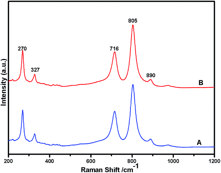
Fig. 1 shows the powder XRD pattern of the prepared 5% Ni/WO3 catalyst. The XRD pattern of the catalyst (Fig. 1d) showed peaks at the 2θ values of 23.1°, 23.8°, 24.6°, 33.5°, and 34.3°, which correspond to the monoclinic WO3 (JCPDS no. 43-1035, space group: P21/n). Moreover, XRD peaks corresponding to NiO (Fig. 1b) were not clearly observed in the prepared catalyst; this indicated that the NiO nanoparticles were highly dispersed on the WO3 support or the particle growth of NiO was slow. A new peak at 31.1° was observed in the XRD pattern shown in Fig. 1c and d; this peak was attributed to the diffraction pattern of NiWO4.44 The surface vibrational spectra of tungsten oxide in 5% Ni/WO3 material were obtained by Raman spectroscopy, and the results are shown in Fig. 2. In the Raman spectrum of Ni/WO3 (Fig. 2a), five bands at 270 cm−1, 327 cm−1, 716 cm−1, 805 cm−1, and 890 cm−1 were observed, which were due to bending mode, antisymmetric stretch, and symmetric stretch of WO3. The intense band at 270 cm−1 and weak band at 327 cm−1 were due to the bending vibration of the O–W–O bond. On the other hand, the intense bands at 716 and 805 cm−1 correspond to the antisymmetric and symmetric stretching vibration of the O–W–O bond, respectively. A small weak band was seen at 890 cm−1, which corresponded to the characteristic stretching vibration of short terminal O–W–O bonds of the WO4 unit cell.27 This analysis result indicates that the presence of Ni in the 5% Ni/WO3 material yields NiWO4 on the surface of the mixed oxides materials. Therefore, XRD and Raman spectra have shown that a small amount of NiWO4 is formed during the preparation of 5% Ni/WO3 materials. The surface area of the prepared 5% Ni/WO3 catalyst is 58 m2 g−1 and that of the 5% Ni/WOimp3 conventional catalyst is 12 m2 g−1. Hence, the surface area of the prepared catalyst is 5 times higher than that of the conventional catalyst.
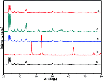 |
| | Fig. 1 XRD patterns of (a) commercial W(VI) oxide, (b) commercial NiO, (c) NiO/WO3 (wet imp.), (d) fresh NiO/WO3, and (e) spent NiO/WO3. | |
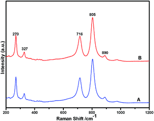 |
| | Fig. 2 Raman spectra of Ni(II)/WO3 catalyst; (A) fresh catalyst and (B) spent catalyst. | |
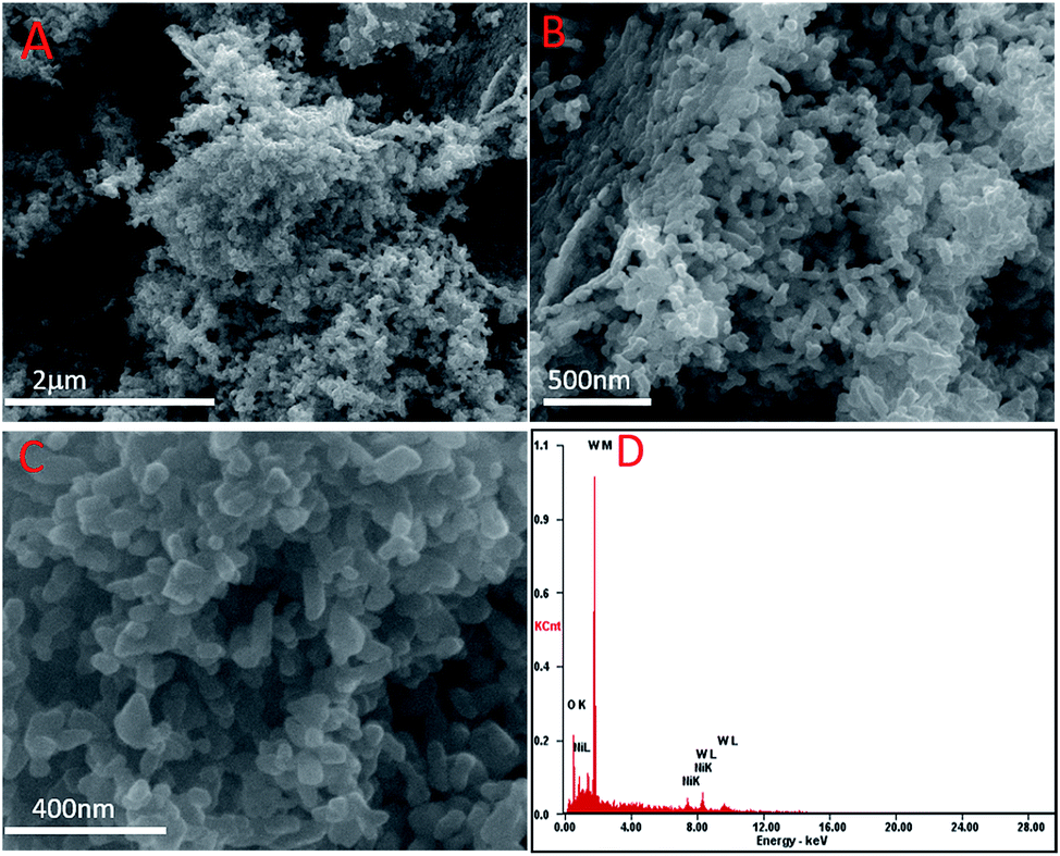
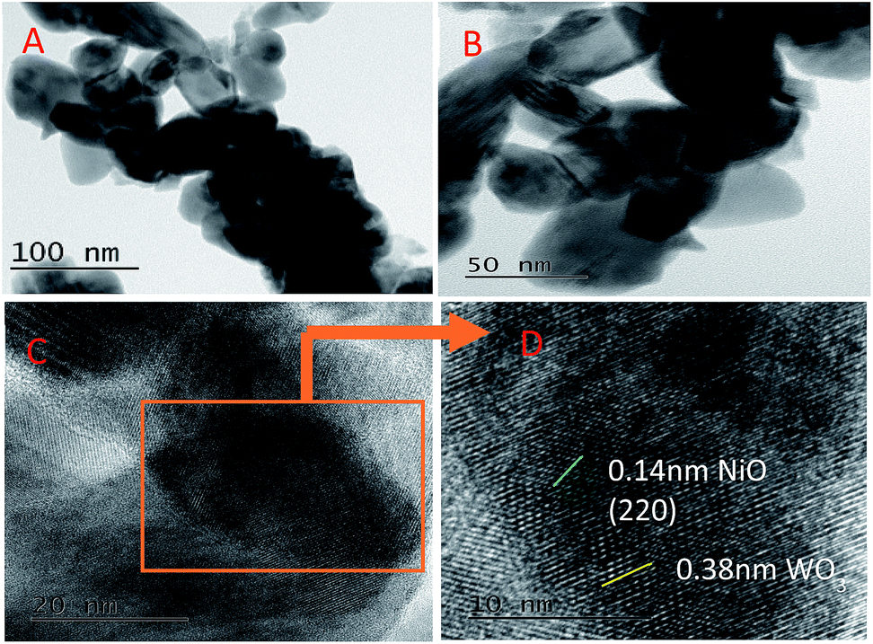
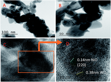
The representative SEM images of the 5% Ni/WO3 catalyst are shown in Fig. 3. It can be seen that most of the particles are homogenously distributed, and few particles are mixed together with some distorted shape. The electron diffraction (ED) pattern of the catalyst showed only the presence of nickel, oxygen, and tungsten, and no impurity could be observed in the spectra (ESI-S1†) and elemental mapping (ESI-S2†). However, in the HRTEM images (Fig. 4), it was difficult to distinguish the particles of Ni and WO3. From the HRTEM images, the average particle size is determined to be about 10–20 nm, and the lattice fringes with a d-spacing of 1.4 Å corresponding to the [220] plane of NiO are presented in Fig. 4D, whereas the lattice fringes with a d-spacing of 3.8 Å corresponding to the [020] plane of WO3 can also be seen. The homogenous distribution of Ni metal can be confirmed by the HRTEM elemental mapping (ESI-S3†).
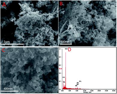 |
| | Fig. 3 SEM images of the as-synthesised Ni/WO3. | |
 |
| | Fig. 4 HR-TEM images of Ni/WO3. | |
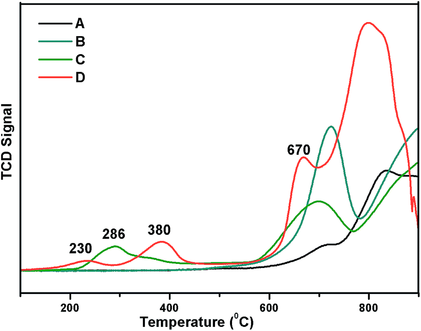
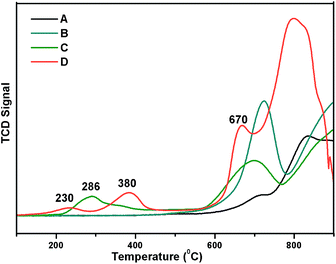
Reducibility of the Ni and W species present in the catalyst was examined by H2-TPR analysis with a 10% H2 balance He gas, as shown in Fig. 5. TPR profiles of the prepared 5% Ni/WO3, 5% Ni/WOimp3 (impregnated), and WO3 (commercial) catalyst are shown in Fig. 5a, b and c, respectively. For the commercial WO3 catalyst, three reduction peaks (W6+, W4+, W2+, W0) are observed between 600 and 900 °C. In the case of 5% Ni/WO3 (impregnated) catalyst, spinel NiWO4 phase with a free WO3 phase was formed, and in the TPR profile, two reduction peaks appeared. The first reduction peak at 705 °C is due the reduction of WO3 species, and the broad peak at higher temperatures (720–920 °C) is due to the reduction of WO3 species and Ni and W species present in the NiWO4 phase. The prepared 5% Ni/WO3 catalyst showed four reduction peaks: the first peak at the Tmax value of 215 °C is due to the reduction of highly dispersed surface NiO species; the second peak at the Tmax value of 380 °C is due to the reduction of Ni2+ species of NiO to metallic Ni, which interacts strongly with WO3; the third peak with a Tmax value of 680 °C corresponds to the reduction of WO3 species. The broad peak between 700 °C and 900 °C is the combination of three reduction peaks, corresponding to the reduction of WO3 and NiWO4. We also prepared a catalyst by physical mixing of commercial WO3 with commercial NiO (5 wt%) denoted as Ni/WOphy3, and the TPR profile of this catalyst is shown in Fig. 5d. The broad peak between 200 °C and 400 °C is the reduction peak for NiO, and the peaks between 580 °C and 900 °C are the reduction peaks for WO3 oxides. We have also carried out metal dispersion analysis for the prepared catalysts with different loadings as well as impregnated catalysts by the H2 chemisorption method (Table 1). Herein, 5% Ni/WO3 impregnated catalyst showed a negligible Ni dispersion of 2.5%, whereas our prepared 5% Ni/WO3 catalyst showed a metal dispersion of 13.6% (Table 1). This clearly indicated that highly dispersed Ni-particles were present in the prepared catalyst, which were the active species for the hydrogenation reaction.
 |
| | Fig. 5 TPR Profile of Ni/WO3 (A) WO3, (B) impregnated 5% Ni/WO3, (C) physically mixed Ni/WO3, and (D) our prepared 5% Ni/WO3. | |
Table 1 Physiochemical properties of the catalystsa
| Catalyst |
BET surface area (m2 g−1) |
Ni dispersion (%) |
|
Impregnatedimp.
|
| WO3 |
64.9 |
— |
| 2% Ni/WO3 |
52.7 |
14.8 |
| 3% Ni/WO3 |
51.9 |
13.9 |
| 4% Ni/WO3 |
49.8 |
13.3 |
| 5% Ni/WO3 |
48.7 |
13.6 |
| 5% Ni/WOimp3 |
12.8 |
2.5 |
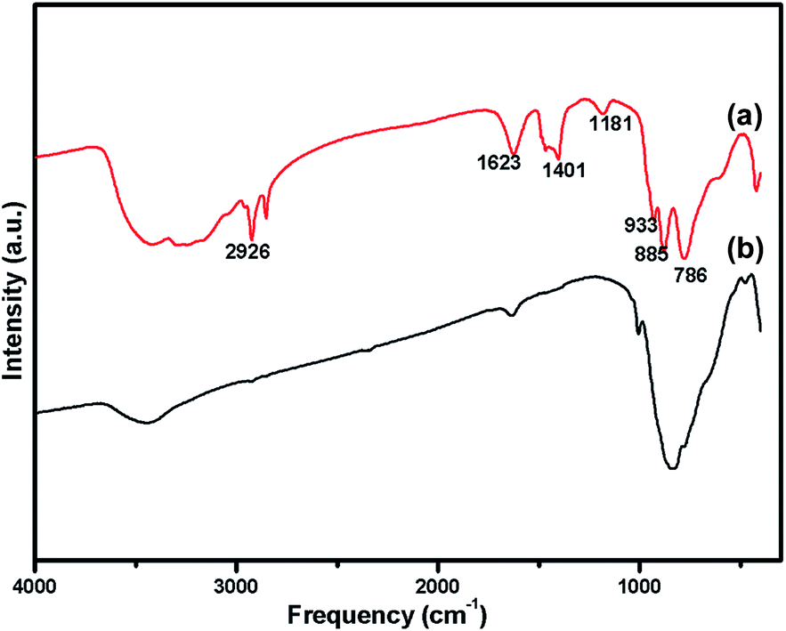
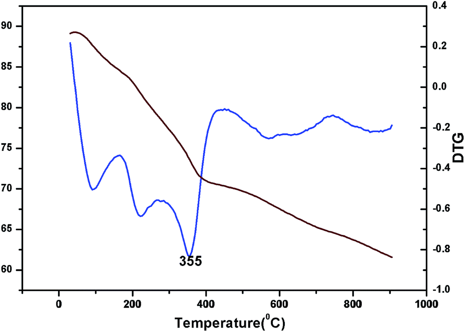
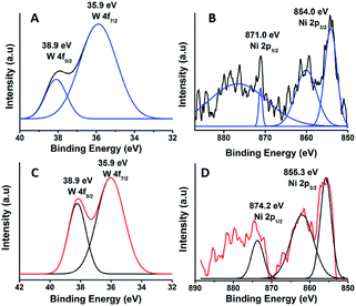
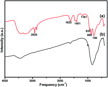
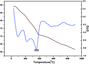
The oxidation state of Ni and tungsten on the surface of the catalyst was analysed by X-ray photoelectron spectroscopy. Fig. 6A and B present the core level Ni 2p XPS spectra of the fresh and spent catalysts. The spectra of Ni 2p are characterized by the two spin orbit components Ni 2p3/2 and Ni 2p1/2 separated by 17 eV, and two make-up satellite peaks were observed with the binding energy difference of 6 eV. The peak at the binding energy value of 854.0 eV for the fresh catalyst indicates the presence of Ni2+ (NiO) on the surface of the catalyst. As shown in the XPS spectra of the spent catalyst, the peak at 855.3 eV indicated the presence of NiOH in the catalyst. This is due to water present in the catalytic system and exposure to air at the time of analysis. The W 4f XPS patterns of the fresh and spent catalysts are shown in Fig. 6C and D, which show the unchanged oxidation state of W species (which is W6+). To check the association of the surfactant cetyltrimethylammonium bromide (CTAB) with the 5% Ni/WO3 moiety, the FTIR spectra of the 5% Ni/WO3 catalyst were obtained before and after thermal treatment. The as-synthesized sample showed that the presence of an organic moiety in the catalyst suggested the interaction of the surfactant CTAB with the catalyst. The peak at 1401 cm−1 corresponds to the symmetric stretching vibration of the CH3–N+ moiety. The frequency between 1100 and 3000 cm−1 may be due to the CH2 symmetric and anti-symmetric vibration regions.45 However, after thermal treatment, the absence of the organic moiety reflects the complete removal of CTAB during calcination (Fig. 7). The TGA curve showed decomposition peaks below 400 °C, well consistent with the decomposition temperature of the surfactant cetyltrimethylammonium bromide (CTAB) (Fig. 8).
 |
| | Fig. 6 XPS of (A & B) fresh and (C & D) spent NiWO3 catalyst. | |
 |
| | Fig. 7 FTIR Spectra of (a) uncalcined Ni/WO3 catalyst (b) after calcination at 550 °C of Ni/WO3 catalyst. | |
 |
| | Fig. 8 TG and DTG of Ni/WO3 before calcination. | |
Catalytic activity
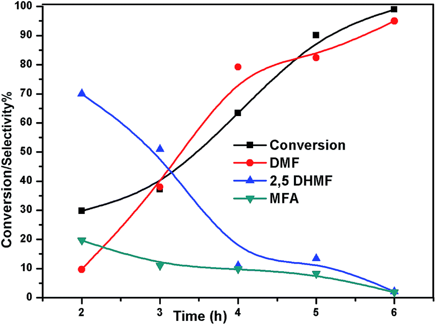
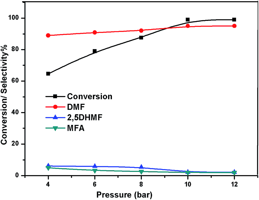
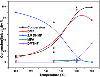
The effect of reaction temperature on the HMF hydrogenation and DMF yield over the 5% Ni/WO3 catalyst was thoroughly investigated by varying the temperature in the 100–200 °C range. The HMF conversions and DMF yields are shown in Fig. 9. It can be clearly seen that temperature plays an important role in the HMF conversion: as the temperature increases, conversion of HMF also increases. After 6 h of reaction, HMF conversion increased from 11% to >99% when the reaction temperature increased from 150 to 180 °C, respectively. Moreover, the reaction temperature has a profound influence on the DMF yield, as can be seen in Fig. 9. The DMF yield increased continuously as the reaction temperature was increased from 100 to 180 °C; this indicated that the intermediates 2,5-dihydroxy methyl furan (2,5 DHMF) and MFA (methyl furfuryl alcohol) that were formed during the course of the reaction were converted to DMF with the increasing reaction temperature. At a reaction temperature of 180 °C, a high DMF yield of 95% can be achieved after 6 h of reaction time. However, the DMF yield was decreased upon further increasing the reaction temperature to 200 °C. This decrease in the DMF yield could be attributed to its ring hydrogenation, leading to the formation of DMTHF (di-methyl tetrahydrofuran). Thus, 180 °C seems to be the optimum temperature to obtain a >95% yield of DMF after 6 h of reaction with this catalyst. The effect of reaction time for the hydrogenation of HMF and the selectivity of DMF is shown in Fig. 10. To find out the possible reaction intermediates during the reaction, the aliquots of the reaction were obtained at regular intervals and injected to GC. During the analysis of aliquots, we found the formation of three compounds, which were DMF, 2,5 DHMF, and MFA. It is observed that during the initial course of reaction (till 3 h), the conversion of HMF reaches up to >37%, but the selectivity of DMF is less than that of 2,5 DHMF. With prolonged reaction time (>3 h), rapid change in conversion of HMF (>99%) was noticed, and the selectivity of DMF reached up to >95% after 6 h. The detailed kinetic study shows that there is no diffusion limit, and it is also not a control reaction. The results shown in Table 3 indicated the combined effect of the presence of Ni and WO3 in the catalyst. When only NiO oxide (entry 7) was used as a catalyst, conversion of HMF was 28%, and there was no DMF formation; however, 92% yield of DMHF was obtained. When we performed the reaction with WO3, the conversion of HMF was 45%, MF (methyl furfural) selectivity was >91%, and DMF was not produced. From the abovementioned results, it is clear that Ni favours the hydrogenation,46 and WO3 favours the hydrogenolysis.39,47 To understand the effect of NiWO4 on hydrogenolysis, NiWO4 was prepared48 and tested (entry 10), and it was found that there was no sufficient conversion of HMF; hence, it could be concluded that there was no effect of NiWO4 on this reaction. To optimise the Ni content in the catalyst, catalysts with different Ni loadings were prepared and evaluated for HMF hydrogenation. The HMF conversions and product yields are summarized in Table 3. Catalyst with a 5 wt% Ni loading showed the highest activity in terms of HMF hydrogenation, yielding 95% DMF with >99% HMF conversion (entry 5, Table 2). However, under similar reaction conditions, HMF conversions were only 27, 37, and 56% when the Ni loadings were 2 wt%, 3 wt%, and 4 wt% of catalysts, respectively. When Ni loading was above 5 wt%, it was noticed that there was no significant change in the conversion of HMF and selectivity of DMF (entry 6 Table 2). H2 pressure directly affects the conversion of HMF and the selectivity of DMF, as shown in Fig. 11. H2 pressure was increased from 4.0 to 12 bar, keeping all the reaction parameters constant. At low pressure 4.0 bar, the conversion of HMF was 65%, and the selectivity of DMF was 89% as the H2 pressure reached up to 10 bar; >99% conversion of HMF and >95% selectivity of DMF were achieved. Further increase in H2 pressure to 12 bar resulted in no remarkable change in the conversion of HMF and selectivity of DMF. Therefore, the 10 bar H2 pressure is optimum for the hydrogenation of HMF for this catalytic system. It is well known that water can be an excellent solvent for different chemical reactions49 and also accelerates the chemical reactions.42 To check the effect of water on HMF hydrogenation, HMF hydrogenation was carried out with different organic solvents (Table 2). From Table 2, it is evident that the activity of catalyst is strongly dependent on the solvent used. Among different solvents, water showed the highest selectivity of DMF. In the case of iso-propanol, although the catalyst showed some conversion, the selectivity of DMF was very poor. In the case of THF, the conversion of HMF was low; however, the selectivity of DMF was higher than that of isopropanol. Chatterjee et al. explained a simple approach of donor and acceptor numbers of solvents and the δ values of the solvents.50,51 Water has the highest negative δ value and accepts electrons. Water also forms hydrogen bonds, which provide better catalytic activity.52 Hence, water attributed good correlation between Lewis acidity of the catalyst and HMF conversion.53–55
 |
| | Fig. 9 Effect of temperature on the conversion of HMF and selectivity of different products. Reaction conditions: 0.05 g of HMF in 20 ml, reduced catalyst 0.05 g, pressure 1 MPa, and temperature 180 °C. | |
 |
| | Fig. 10 Effect of time on conversion of HMF and selectivity of different products. Reaction conditions: 0.05 g of HMF in 20 ml, reduced catalyst 0.05 g, pressure 1 MPa, and temperature 180 °C. | |
Table 2 Effect of different solvents on the HMF hydrogenation
| S. No. |
Solvent |
Con. (%) |
Product selectivity (%) |
Others |
| BHMF |
MFA |
DMF |
| 1 |
Water |
99 |
2.1 |
1.9 |
95 |
0 |
| 2 |
Ethanol |
47 |
65 |
2.8 |
24.6 |
7.6 |
| 3 |
Isopropanol |
49 |
64.6 |
1.4 |
29 |
3.6 |
| 4 |
THF |
13 |
12.8 |
34.6 |
40.8 |
11.8 |
| 5 |
Hexane |
9.8 |
48.7 |
1.3 |
17.7 |
32.3 |
Table 3 Activity of catalysts with different Ni loadings on support and activity of pure Ni oxide and tungsten oxidea
| Sr. No. |
Catalyst |
Ni content (wt%) |
HMF con. (%) |
Selectivity (%) |
| DMF |
DHMF |
MFA/MFb |
|
Reaction conditions: 0.05 g of HMF in 20 ml, reduced catalyst 0.05 g, pressure 1 MPa, temperature 180 °C, and time 6 h.
Indicates formation of MF.
|
| 1 |
1% Ni/WO3 |
1 |
13 |
3.2 |
78 |
19 |
| 2 |
2% Ni/WO3 |
2 |
27 |
37 |
39 |
24 |
| 3 |
3% Ni/WO3 |
3 |
37 |
47.2 |
23.6 |
29.2 |
| 4 |
4% Ni/WO3 |
4 |
56 |
59.1 |
17.9 |
23 |
| 5 |
5% Ni/WO3 |
5 |
>99 |
95 |
1.9 |
2.1 |
| 6 |
7% Ni/WO3 |
7 |
>99 |
96 |
0.9 |
1.1 |
| 7 |
NiO |
— |
28 |
— |
92 |
8 |
| 8 |
WO3 |
— |
45 |
— |
8.5 |
91.5b |
| 9 |
NiWO4 |
— |
— |
— |
— |
90b |
| 10 |
5% NiO/WOimp3 |
5 |
32 |
17.4 |
43.6 |
39 |
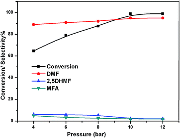 |
| | Fig. 11 Effect of pressure. | |
Proposed reaction mechanism
To understand the reaction mechanism of the hydrogenation of HMF to DMF, we examined the intermediate product distribution at different reaction times using the Ni/WO3 catalyst, and the results are shown in Fig. 10. When the reaction time was increased from 1 to 6 h, the conversion of HMF increased from 13% to 99%, respectively, and the concentration of the products changed in a complex manner. The selectivity of DMF increased continuously with the increasing reaction time, whereas the yield of 2,5 DHMF reached a maximum of 51% at 3 h and then decreased with the increasing reaction time. MFA was also observed in the product. Initially, the low yield of 2,5 DHMF may be attributed to the fact that the first step is very slow. The reduction process occurs step by step, where initially, HMF further reduces to 2,5 dihydroxy methyl furan (2,5 DHMF), which reduces to methyl furfural alcohol (MFA), and finally, MFA reduces to DMF. 2,5 DHMF and MFA were separately subjected to reduction process over the Ni/WO3 catalyst, and it was found that when 2,5 DHMF was used as a substrate, it took 5.5 h to obtain DMF (∼95%), and MFA took 1.5 h to produce DMF (∼95% yield). Hence, HMF to 2,5 DHMF and MFA to DMF step is very fast. Based on these results, a possible reaction pathway of the hydrogenation of HMF to DMF is proposed in Scheme 1, and the possible reaction mechanism is proposed in ESI-Scheme 2.†
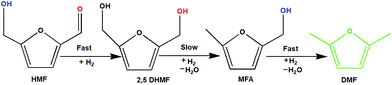 |
| | Scheme 1 Possible reaction pathway. | |
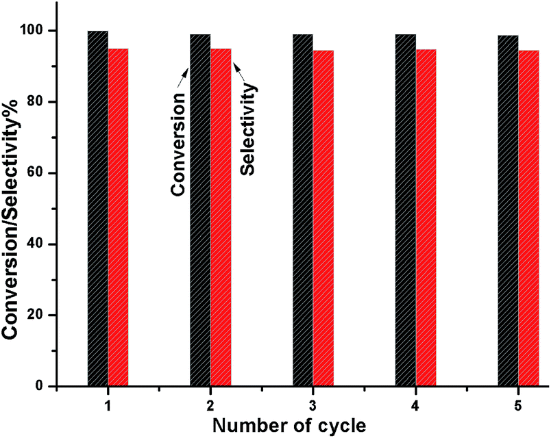
Reusability of the catalyst
To check whether the catalyst is truly heterogeneous or not, the catalytic hydrogenation reaction of 5-HMF was carried out with the spent catalyst under same reaction conditions. The activity of the recovered catalyst after 5 consecutive runs did not lead to any significant decline in its catalytic activity in terms of conversion and selectivity (Fig. 12). After completion of the reaction, the solid catalyst was removed from the reaction mixture by filtration under the hot conditions, and the reaction was allowed to proceed with the filtrate under the same conditions. The reaction was completely stopped after the removal of the catalyst. The leaching test was performed for Ni and W by ICP-AES analysis using the filtrate, and it was found that neither Ni nor W was present in the filtrate. We also observed that the amount of Ni and W present in the spent catalyst after 5 cycles of reuse was the same as that of the fresh catalyst, as determined by ICP-AES. XPS analysis also confirmed that the Ni and W concentration for the fresh and spent catalyst on the surface was the same. The TEM analysis also showed the same morphology of the catalyst. Hence, the catalyst is truly heterogeneous in nature. The Raman spectra of the fresh and spent catalyst are almost the same; this further suggests the structural stability of the nanostructured catalyst under the reaction conditions, which is a prerequisite for practical applications.
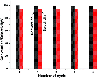 |
| | Fig. 12 Catalyst reusability test for the conversion HMF and DMF selectivity. | |
Conclusions
Herein, we have described a facile preparation method for the synthesis of nanostructured NiO-supported WO3 for the hydrogenation of 5-HMF to dimethylfuran (DMF). The catalyst shows >99% conversion of 5-HMF with >95% selectivity after 6 h. The catalyst was characterized by XRD, XPS, ICP-AES, FTIR and Raman spectroscopy, SEM, and TEM. The activity of the catalyst depends on the Ni loading. The enhanced activity is likely caused by the presence of highly dispersed Ni-nanoparticles on the nanostructured WO3. The catalyst did not show any leaching after 5 cycles of reuse; this confirmed the true heterogeneity of the catalyst. This nickel-based catalyst has significant potential for further development and is expected to pave the way for realising the goal of renewable liquid fuels from biomass.
Conflicts of interest
There are no conflicts to declare.
Acknowledgements
R. B. thanks CSIR, New Delhi, for providing the financial support in the form of the 12 FFYP (CSC-0117 and CSC-0125). We also acknowledge the Director CSIR-IIP for his support. The authors thank the Analytical Science Division, CSIR-Indian Institute of Petroleum for analytical services.
References
- M. J. Climent, A. Corma and S. Iborra, Green Chem., 2014, 16, 516 RSC.
- S. I. George, W. Huber and A. Corma, Chem. Rev., 2006, 106, 4044–4098 CrossRef PubMed.
- L. Hu, G. Zhao, W. Hao, X. Tang, Y. Sun, L. Lin and S. Liu, RSC Adv., 2012, 2, 11184 RSC.
- J. B. Binder and R. T. Raines, J. Am. Chem. Soc., 2009, 131(5), 1979–1985 CrossRef CAS PubMed.
- R. Alamillo, M. Tucker, M. Chia, Y. Pagán-Torres and J. Dumesic, Green Chem., 2012, 14, 1413 RSC.
- D. M. Alonso, J. Q. Bond and J. A. Dumesic, Green Chem., 2010, 12, 1493 RSC.
- J. J. Bozell and G. R. Petersen, Green Chem., 2010, 12, 539 RSC.
- R. Carrasquillo-Flores, M. Käldström, F. Schüth, J. A. Dumesic and R. Rinaldi, ACS Catal., 2013, 3, 993–997 CrossRef CAS.
- J. M. R. Gallo, D. M. Alonso, M. A. Mellmer and J. A. Dumesic, Green Chem., 2013, 15, 85–90 RSC.
- B. Girisuta, L. Janssen and H. Heeres, Green Chem., 2006, 8, 701–709 RSC.
- G. Wang, Z. Zhang and L. Song, Green Chem., 2014, 16, 1436–1443 RSC.
- J. Jae, W. Zheng, A. M. Karim, W. Guo, R. F. Lobo and D. G. Vlachos, ChemCatChem, 2014, 6, 848–856 CrossRef CAS.
- I. Sádaba, Y. Y. Gorbanev, S. Kegnæs, S. S. R. Putluru, R. W. Berg and A. Riisager, ChemCatChem, 2013, 5, 284–293 CrossRef.
- B. Saha, D. Gupta, M. M. Abu-Omar, A. Modak and A. Bhaumik, J. Catal., 2013, 299, 316–320 CrossRef CAS.
- Z. Zhang, J. Zhen, B. Liu, K. Lv and K. Deng, Green Chem., 2015, 17, 1308–1317 RSC.
- H. Ait Rass, N. Essayem and M. Besson, ChemSusChem, 2015, 8, 1206–1217 CrossRef CAS PubMed.
- R.-J. van Putten, J. C. van der Waal, E. De Jong, C. B. Rasrendra, H. J. Heeres and J. G. de Vries, Chem. Rev., 2013, 113, 1499–1597 CrossRef CAS PubMed.
- S. P. Teong, G. Yi and Y. Zhang, Green Chem., 2014, 16, 2015–2026 RSC.
- J. Ohyama, R. Kanao, Y. Ohira and A. Satsuma, Green Chem., 2016, 18, 676–680 RSC.
- S. Dutta, S. De and B. Saha, ChemPlusChem, 2012, 77, 259–272 CrossRef CAS.
- M. Braun and M. Antonietti, Green Chem., 2017, 19, 3813–3819 RSC.
- Y. Román-Leshkov, J. N. Chheda and J. A. Dumesic, Science, 2006, 312, 1933–1937 CrossRef PubMed.
- T. Thananatthanachon and T. B. Rauchfuss, Angew. Chem., Int. Ed., 2010, 49, 6616–6618 CrossRef CAS PubMed.
- M. Chidambaram and A. T. Bell, Green Chem., 2010, 12, 1253 RSC.
- S. De, S. Dutta and B. Saha, ChemSusChem, 2012, 5, 1826–1833 CrossRef CAS PubMed.
- J. Jae, W. Zheng, R. F. Lobo and D. G. Vlachos, ChemSusChem, 2013, 6, 1158–1162 CrossRef CAS PubMed.
- T. S. Hansen, K. Barta, P. T. Anastas, P. C. Ford and A. Riisager, Green Chem., 2012, 14, 2457–2461 RSC.
- P. Nilges and U. Schröder, Energy Environ. Sci., 2013, 6, 2925–2931 CAS.
- A. B. Gawade, M. S. Tiwari and G. D. Yadav, ACS Sustainable Chem. Eng., 2016, 4(8), 4113–4123 CrossRef CAS.
- J. Chen, R. Liu, Y. Guo, L. Chen and H. Gao, ACS Catal., 2015, 5, 722–733 CrossRef CAS.
- L. Hu, X. Tang, J. Xu, Z. Wu, L. Lin and S. Liu, Ind. Eng. Chem. Res., 2014, 53, 3056–3064 CrossRef CAS.
- N. Perret, A. Grigoropoulos, M. Zanella, T. D. Manning, J. B. Claridge and M. J. Rosseinsky, ChemSusChem, 2016, 9, 521–531 CrossRef CAS PubMed.
- J. Ren, M. Antonietti and T.-P. Fellinger, Adv. Energy Mater., 2015, 5, 1401660 CrossRef.
- W. Guo, H. Liu, S. Zhang, H. Han, H. Liu, T. Jiang, B. Han and T. Wu, Green Chem., 2016, 18, 6222–6228 RSC.
- P. Yang, Q. Cui, Y. Zu, X. Liu, G. Lu and Y. Wang, Catal. Commun., 2015, 66, 55–59 CrossRef CAS.
- P. Yang, Q. Xia, X. Liu and Y. Wang, Fuel, 2017, 187, 159–166 CrossRef CAS.
- R. Ramos, A. Grigoropoulos, N. Perret, M. Zanella, A. P. Katsoulidis, T. D. Manning, J. B. Claridge and M. J. Rosseinsky, Green Chem., 2017, 19, 1701–1713 RSC.
- B. Saha, C. M. Bohn and M. M. Abu-Omar, ChemSusChem, 2014, 7, 3095–3101 CrossRef CAS PubMed.
- Y. B. Huang, M. Y. Chen, L. Yan, Q. X. Guo and Y. Fu, ChemSusChem, 2014, 7, 1068–1072 CrossRef CAS PubMed.
- K. Fabičovicová, O. Malter, M. Lucas and P. Claus, Green Chem., 2014, 16, 3580–3588 RSC.
- R. Goyal, B. Sarkar, A. Bag, N. Siddiqui, D. Dumbre, N. Lucas, S. K. Bhargava and A. Bordoloi, J. Catal., 2016, 340, 248–260 CrossRef CAS.
- M. C. Pirrung, Chemistry, 2006, 12, 1312–1317 CrossRef CAS PubMed.
- P. A. Grieco, J. J. Nunes and M. D. Gaul, J. Am. Chem. Soc., 1990, 112, 4595–4596 CrossRef CAS.
- B. Solsona, J. M. López Nieto, P. Concepción, A. Dejoz, F. Ivars and M. I. Vázquez, J. Catal., 2011, 280, 28–39 CrossRef CAS.
- H. Chen, Y. Wang, Y. Wang, S. Dong and E. Wang, Polymer, 2006, 47, 763–766 CrossRef CAS.
- X. Kong, Y. Zhu, H. Zheng, X. Li, Y. Zhu and Y.-W. Li, ACS Catal., 2015, 5, 5914–5920 CrossRef CAS.
- H. Ren, Y. Chen, Y. Huang, W. Deng, D. G. Vlachos and J. G. Chen, Green Chem., 2014, 16, 761–769 RSC.
- M. M. Mohamed, S. A. Ahmed and K. S. Khairou, Appl. Catal., B, 2014, 150–151, 63–73 CrossRef CAS.
- I. T. Horváth, Green Chem., 2008, 10, 1024 RSC.
- M. Chatterjee, T. Ishizaka and H. Kawanami, Green Chem., 2014, 16, 4734–4739 RSC.
- Viktor_Gutmann.
- L. R. Merte, G. Peng, R. Bechstein, F. Rieboldt, C. A. Farberow, L. C. Grabow, W. Kudernatsch, S. Wendt, E. Lægsgaard and M. Mavrikakis, Science, 2012, 336, 889–893 CrossRef CAS PubMed.
- C. H. Yen, H. W. Lin and C.-S. Tan, Catal. Today, 2011, 174, 121–126 CrossRef CAS.
- S. Minakata and M. Komatsu, Chem. Rev., 2008, 109, 711–724 CrossRef PubMed.
- Y. Marcus, Chem. Soc. Rev., 1993, 22, 409–416 RSC.
Footnote |
| † Electronic supplementary information (ESI) available. See DOI: 10.1039/c7se00363c |
|
| This journal is © The Royal Society of Chemistry 2018 |
Click here to see how this site uses Cookies. View our privacy policy here. 
 a,
Rubina
Khatun
a,
Chandrashekar
Pendem
a,
Appala Naidu
Chokkapu
a,
Ankur
Bordoloi
a and
Rajaram
Bal
a,
Rubina
Khatun
a,
Chandrashekar
Pendem
a,
Appala Naidu
Chokkapu
a,
Ankur
Bordoloi
a and
Rajaram
Bal